EP0416370A2 - Method and device for detecting and indentifying sensor errors - Google Patents
Method and device for detecting and indentifying sensor errors Download PDFInfo
- Publication number
- EP0416370A2 EP0416370A2 EP90116029A EP90116029A EP0416370A2 EP 0416370 A2 EP0416370 A2 EP 0416370A2 EP 90116029 A EP90116029 A EP 90116029A EP 90116029 A EP90116029 A EP 90116029A EP 0416370 A2 EP0416370 A2 EP 0416370A2
- Authority
- EP
- European Patent Office
- Prior art keywords
- vector
- sensors
- error
- sensor signals
- state variables
- Prior art date
- Legal status (The legal status is an assumption and is not a legal conclusion. Google has not performed a legal analysis and makes no representation as to the accuracy of the status listed.)
- Granted
Links
Images


Classifications
-
- G—PHYSICS
- G06—COMPUTING; CALCULATING OR COUNTING
- G06F—ELECTRIC DIGITAL DATA PROCESSING
- G06F11/00—Error detection; Error correction; Monitoring
- G06F11/07—Responding to the occurrence of a fault, e.g. fault tolerance
- G06F11/16—Error detection or correction of the data by redundancy in hardware
- G06F11/18—Error detection or correction of the data by redundancy in hardware using passive fault-masking of the redundant circuits
- G06F11/187—Voting techniques
- G06F11/188—Voting techniques where exact match is not required
-
- G—PHYSICS
- G01—MEASURING; TESTING
- G01C—MEASURING DISTANCES, LEVELS OR BEARINGS; SURVEYING; NAVIGATION; GYROSCOPIC INSTRUMENTS; PHOTOGRAMMETRY OR VIDEOGRAMMETRY
- G01C25/00—Manufacturing, calibrating, cleaning, or repairing instruments or devices referred to in the other groups of this subclass
-
- G—PHYSICS
- G05—CONTROLLING; REGULATING
- G05B—CONTROL OR REGULATING SYSTEMS IN GENERAL; FUNCTIONAL ELEMENTS OF SUCH SYSTEMS; MONITORING OR TESTING ARRANGEMENTS FOR SUCH SYSTEMS OR ELEMENTS
- G05B9/00—Safety arrangements
- G05B9/02—Safety arrangements electric
- G05B9/03—Safety arrangements electric with multiple-channel loop, i.e. redundant control systems
-
- G—PHYSICS
- G06—COMPUTING; CALCULATING OR COUNTING
- G06F—ELECTRIC DIGITAL DATA PROCESSING
- G06F11/00—Error detection; Error correction; Monitoring
- G06F11/07—Responding to the occurrence of a fault, e.g. fault tolerance
- G06F11/08—Error detection or correction by redundancy in data representation, e.g. by using checking codes
- G06F11/10—Adding special bits or symbols to the coded information, e.g. parity check, casting out 9's or 11's
-
- G—PHYSICS
- G06—COMPUTING; CALCULATING OR COUNTING
- G06F—ELECTRIC DIGITAL DATA PROCESSING
- G06F11/00—Error detection; Error correction; Monitoring
- G06F11/07—Responding to the occurrence of a fault, e.g. fault tolerance
- G06F11/16—Error detection or correction of the data by redundancy in hardware
- G06F11/18—Error detection or correction of the data by redundancy in hardware using passive fault-masking of the redundant circuits
- G06F11/183—Error detection or correction of the data by redundancy in hardware using passive fault-masking of the redundant circuits by voting, the voting not being performed by the redundant components
Definitions
- a gyro may provide a rotational speed around axes that include angles with the axes by which the rotational speed is to be measured. Such differently oriented gyros are used in particular to generate redundant signals with a minimum of components.
- the state variable to be measured can be a speed over ground, which is measured by means of a Doppler radar.
- the measured variable is a frequency shift.
- the frequency shift is related to the speed to be measured via physical and geometric relationships.
- a thermocouple supplies a voltage as a measured variable.
- the state variable "temperature” is obtained from this by means of a calibration factor.
- the redundancy manifests itself in the fact that the order of the measurement vector m is greater than the order of the state vector x , that is to say that more measured quantities are recorded than state quantities have to be determined.
- redundant sensors are provided for the individual state variables in order to achieve the required reliability.
- a set of redundant gyroscopes both for flight control, that is to say for stabilizing the aircraft, and for navigation.
- information about state variables can often be obtained from fundamentally different sensor systems.
- speed information can be available from the signals from accelerometers of the flight controller by integration and, at the same time, from a Doppler radar provided for other purposes.
- redundancy of similar sensors we shall speak of "similar” redundancy here.
- a redundancy that is obtained by obtaining the same state variable from sensors with different functions should be referred to as “dissimilar” redundancy.
- Similar and dissimilar redundancy can be mathematically described by means of a measurement equation of the type specified at the beginning with a suitable measurement matrix H. Such a consideration, which relates all the measured variables measured with the existing sensors via a measurement matrix to all sought state variables, often results in a significantly higher degree of redundancy than if one merely relies on the physical, "similar" redundancy of similar sensors.
- the errors that occur with sensors can be of various types.
- the errors can simply consist of a sensor failure.
- the signal may also deteriorate, which ultimately leads to the signal no longer being usable.
- the invention relates to a method for detecting errors in such an arrangement of sensors that are similarly or dissimilarly redundant.
- DE-A1-36 34 023 and EP-A2-0 263 777 show an integrated, redundant reference system for flight control and for generating course and position information.
- a plurality of biaxial, electrically constrained, dynamically tuned gyros are fixed to the aircraft so that they provide redundant angular velocity information.
- a plurality of accelerometers provide redundant acceleration information accordingly.
- First signal processing means contain means for error detection and deactivation, so that incorrect angular velocity or acceleration information is eliminated.
- the error-corrected angular velocity and acceleration information provide stabilization signals for the flight controller.
- Second signal processing means receive the error-corrected and possibly integrated angular velocity and acceleration information and deliver course and position reference signals therefrom.
- the invention has for its object to provide a method and an apparatus for detecting and identifying errors in sensors, which is also useful for dissimilar redundant sensors and also for "midvalue” or “soft failures” of the type described above.
- the parity vector is formed from the measured values. It can be shown that the scalar product of the parity vector with itself is below a threshold value in the case of fully functional sensors and, if an error occurs, exceeds this threshold value. Localization functions can be derived from the components of the parity vector. If the said scalar product exceeds the threshold value, ie signals the presence of an error, the maximum localization function in each case provides an indication of which sensor is delivering the error. Of course, this evaluation is carried out automatically by means of a computer. The computer provides an indication of which sensor is defective. This initiates an automatic reconfiguration, which uses the remaining sensors to generate usable state variables for the control or regulation.
- the maximum localization function then indicates an error in the associated pair of sensor signals.
- the sensors are advantageously subjected to the following test steps in succession: - function monitoring, a plausibility check, in which it is checked whether the measured values obtained in each case are in accordance with the dynamic properties of the system, a majority analysis, in which the state variables obtained from the signals of different sensors are compared with one another, sensors, the measured variables of which lead to state variables which differ significantly from the state variables obtained from the majority of the other sensors, are regarded as faulty, - Monitoring based on the parity vector and comparison with threshold values.
- the results of the test steps are processed after a decision function for deciding on valid or invalid sensor signals. Based on a fault-tolerant, optimal estimate, estimated values for the state variables are formed from the sensor signals, which are considered to be valid, and are output to a control device.
- the invention also relates to a device for recognizing and identifying errors in sensors for state variables which are linked to measurement variables directly supplied by the sensors by means of a measurement equation of the type mentioned above.
- An error in the pair of sensor signals assigned to the maximum localization function can be signaled by the means determining sensor error.
- Means for function monitoring of the sensors are provided as well Means for checking the plausibility of the sensor signals to check whether the measured values obtained in each case are in accordance with the dynamic properties of the system, - Means for carrying out a majority analysis, in which the state variables obtained from the signals of different sensors are compared and compared, sensors, the measured variables of which state variables that differ significantly from the state variables obtained from the majority of the other sensors are regarded as faulty, - The means for monitoring the sensor signals based on the parity vector and the comparison with threshold values.
- Decision means are provided for processing the results of the test steps after a decision function for deciding on valid or invalid sensor signals.
- Reconfiguration means can be used to generate estimated values for the state variables from the sensor signals considered valid after a fault-tolerant, optimal estimate and to connect them to a control device.
- each sensor module contains a two-axis, electrically bound, dynamically tuned gyroscope 18, 20, 22 and 24 and an accelerometer 26, 28, 30 and 32.
- the arrangement corresponds to that in DE-A1- 36 34 023 described execution.
- the information from all four sensor modules 10, 12, 14 and 16 is sent to a unit 34 for error detection, error identification and sensor reconfiguration.
- This unit 34 fulfills the following functions: The unit 34 recognizes and identifies "hard failures", ie the complete failure of sensors, as well as “midvalue failures” and "soft failures". This is represented by block 36. The unit 34 makes a decision as to which sensor is to be regarded as faulty. This is represented by block 38. The unit 34 also contains means 40 for monitoring the software. These agents are the subject of patent application P 39 23 432.0 and are therefore not described in detail here.
- the status information from blocks 38 and 40 is applied to reconfiguration means 42 for the fault-tolerant generation of output data. These output data serve e.g. in the manner described in DE-A1-36 34 023 for flight control and for generating a course and position reference.
- Each individual sensor is initially self-monitored by test devices built into the sensor itself. For example, it can be checked whether a gyro is receiving power or whether the gyro is running, whether the captive circuit is closed, whether a signal is being delivered, etc.
- This self-monitoring is represented by block 44 in FIG. Block 44 receives signals from the monitoring devices at the sensors themselves via inputs 46. This self-monitoring of sensors is generally known per se and is therefore not described in detail here.
- a plausibility check follows the self-monitoring described in block 44. It is checked whether the signals received by sensors 18, 20, 22, 24, 26, 28, 30 and 32 via lines 48 are compatible, for example, with the dynamic properties of the aircraft. Interference signals can be eliminated in this way.
- This plausibility check is represented by a block 50.
- the next monitoring step is a majority assessment. This is represented by block 52 in FIG.
- the usual majority assessment (“Voting Monitoring”) three identical sensors are provided. A sensor is considered to be faulty if the two other sensors deliver matching signals within certain threshold values and the signal of the sensor in question deviates significantly from these signals. This method presents difficulties if the sensors do not deliver nominally the same signals but, for example, rotational speeds around different input axes, as is the case here with the gyros 18, 20, 22 and 24, or accelerations along different axes like the accelerometers 26, 28 , 30 and 32.
- the already mentioned DE-A1-36 40 023 provides a solution to this problem for a special geometric arrangement of the sensors.
- This criterion is applied to all possible combinations of pairs of gyros 18, 20, 22 and 24 or, more generally, sensor modules 10, 12, 14 and 16. This results in an "E ij status" which indicates for which pairs of sensor modules the threshold values are exceeded. A defective sensor module can be determined from this E ij status.
- the majority analysis according to block 52 works according to this principle. This is shown again separately in FIG.
- the m ix and m iy are supplied by the measurement vector m.
- the vectors g ix , g iy and h i are known and stored from the geometry of the arrangement.
- the next step is to identify "midvalue” and "soft failures". This step is represented by a block 54 in FIG.
- a "measurement matrix" H is determined for the present system, which links all the measurement quantities supplied by the sensors, which are combined to form a “measurement vector” m , with all the state quantities required for the control, here for the flight control.
- these are the total of eight signals m ix and m iy from the gyros 18, 20, 22 and 24 and the signals from the accelerometers 26, 28, 30 and 32.
- the output state variables are the rotational speeds p, q, r around the aircraft-fixed ones Axes and the accelerations a x , a y , a z .
- the elements of the measurement matrix contain geometric sizes.
- the measurement matrix can also contain physical quantities if other sensors, for example a Doppler radar or a laser gyroscope, are used to form state variables.
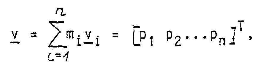
- the column vectors of this matrix P with the components p11, p12, .. p m1 ; p21, p22, .. p m2 ; ... p 1n , p 2n ..p mn form "validation vectors" v i , each of which is assigned to an element of the measurement vector m . These validation vectors are saved.
- the matrix P is an mxn matrix with m ⁇ n. Accordingly, the validation vectors are of the order m ⁇ n. There are n such validation vectors.
- Each validation vector v i is now multiplied in a computer by the associated component m i of the measurement vector m . This results in a "parity vector" v with the components [p1, p2, ... p m ].
- parity vector is an element of the parity space, which is the orthogonal complement of the signal space.
- FIG. 4 shows schematically the formation of the parity vector.
- the components of the measurement vector m so the measured values m1, n m2..m on.
- These components are multiplied in the nodes 58, which can represent multipliers, each with the elements of the matrix P specified there or components of the associated validation vector v i , for example m2 with p12.
- the products are added up to the right and supply the components P1..p m of the parity vector v .
- a "detection function" DF is now formed.
- multipliers 60 on which the components p1, p2 etc. of the parity vector are located and which each multiply these components by themselves and thus deliver p12, P22 etc. These squares are added up along vertical connection 62 and provide DF, as symbolized by a circle.
- the detection function DF is compared with a threshold value E, which is applied to an input 66. If the detection function DF exceeds this threshold value E, an error is signaled at an output 68.
- the components of the parity vector p1, p2, ... p n are multiplied by components p11, p12 etc. of the validation vectors v i .
- the nodes 70 of the network 72 can be regarded as multipliers, which multiply the components p 1, p 2 ... p n of the parity vector v present at the inputs 74 of this network 72 by the adjacent matrix elements p 1 1, etc.
- the products obtained are added up along the vertical connections 76 and provide the localization functions LF i .
- the parity vector v is formed from the measurement vector m and the validation vectors v i in the same way as in FIG.
- the formation of the detection function DF and the comparison of the detection function with a threshold value for recognizing an error is the same as in FIG. 4.
- Corresponding parts are given the same reference numerals in FIG. 5 as in FIG. 4.
- Functions are also formed by multiplying the components p i of the parity vector v by the elements of the matrix P.
- the components of the parity vector v for example p1 are multiplied horizontally by the matrix elements p11, p12, ... p 1n and summed along the vertical connection of the network 72.
- the arrangement of FIG. 5 corresponds to the arrangement of FIG. 4, and here too, corresponding parts are provided with the same reference numerals as in FIG.
- the summation along the vertical connections of the network does not directly provide the localization functions but rather functions ⁇ 1, ⁇ 2, ⁇ 3 ... ⁇ n .
- the status output 80 of the self-monitoring 44, the status output 82 of the plausibility check 50, the status output of the majority consideration 52 and the status output 86 obtained by comparing the parity vector with a threshold value, represented by block 84, are switched to the decision-making means 88.
- the decision-making means provide status information about which of the sensors 18 to 32 are to be regarded as faulty and which are to be regarded as functioning.
- Fig. 6 shows schematically the function of these decision-making means.
- the decision-making means take into account the degree of reliability of the status statements of the various test steps.
- the individual elements of the unit 36 in FIG. 2 generate an error detection status as follows:
- the self-monitoring 44 (BITE) combined with the plausibility check 50 generate a status "B" at the status output 82.
- the majority view 52 generates a status "V” at the status output 84.
- the check 54 based on the parity vector generates a status "P” at a status output 86.
- FIG. 7 A fault is discovered in the entire set "P" and plus in the intersection 100 of the sets “B” and “V". This is shown in FIG. 8 as a logic circuit, "true” or “untrue” being signaled by signals L or H at the three inputs 82, 84 and 86 of the decision-making means 38.
- the inputs 82 and 84 are at the two inputs of an AND gate 102.
- the output 104 of the AND gate 102 and the input 86 are at the inputs of an OR gate 106.
- the output 106 supplies an error detection signal.
- Pr (det) Pr (P) + Pr (BV) * (1-Pr (P)), if Pr (P) is the probability of error detection using the element of the parity vector and Pr (BV) is the combined probability of error detection using self-monitoring and majority consideration.
- the error status signals of the various sensors are given by decision-making means 38 via output 108 to an error-tolerant, optimal estimator 110.
- the estimator 110 generates estimated values of the state variables from the sensor signals which are considered to be correct.
- this estimator 110 is shown schematically in FIG. 9 for the present case of the inertial sensors for the flight control.
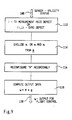
- the next step is a reconfiguration of the matrix M , so that the omission of one or more sensors is taken into account. This is represented by block 116.
- Estimated values for the vector ⁇ are formed with the reconfigured matrix M. This is represented by block 118.
- the estimates thus obtained are sent to an output 120 and applied to the flight controller.
- the matrix M converts the available, redundant measurements into best estimates of orthogonal rotational speeds and accelerations. Proven methods of least squares can be used to optimally estimate the rotational speeds.
Abstract
Description
Die Erfindung betrifft ein Verfahren zum Erkennen und Identifizieren von Fehlern an Sensoren für Zustandsgrößen, die mit von den Sensoren unmittelbar gelieferten Meßgrößen durch eine Meßgleichung
m = H x + ε
verknüpft sind, wobei m ein Vektor der Meßgrößen, x ein Vektor der Zustandsgrößen und H die Meßmatrix ist und wobei die Ordnung von m größer ist als die Ordnung von x.The invention relates to a method for recognizing and identifying faults in sensors for state variables, using measurement variables directly supplied by the sensors using a measurement equation
m = H x + ε
are linked, where m is a vector of the measured variables, x is a vector of the state variables and H is the measurement matrix and the order of m is greater than the order of x .
Auf vielen Gebieten der Technik ist es erforderlich Zustandsgrößen mit hoher Zuverlässigkeit zu messen. Diese Zustandsgrößen bilden die Basis für eine Regelung. Fehler in dieser Regelung können schwerwiegende Folgen haben, beispielsweise zum Absturz eines Flugzeuges führen oder einen Störfall an einem Kernkraftwerk oder einem chemischen Prozess verursachen.In many areas of technology it is necessary to measure state variables with high reliability. These state variables form the basis for regulation. Errors in this regulation can have serious consequences, for example, an aircraft crash or an accident at a nuclear power plant or a chemical process.
Um die erforderliche hohe Zuverlässigkeit zu erzielen, ist es bekannt, Sensoren mehrfach redundant vorzusehen.In order to achieve the required high reliability, it is known to provide sensors with multiple redundancies.
Dabei liefert der Sensor häufig nicht unmittelbar die zu messende Zustandsgröße: Ein Kreisel liefert u.U. eine Drehgeschwindigkeit um Achsen, die mit den Achsen, um welche die Drehgeschwindigkeit gemessen werden soll, Winkel einschließen. Solche unterschiedlich orientierten Kreisel dienen insbesondere zur Erzeugung redundanter Signale mit einem Minimum an Bauteilen. Die zu messende Zustandsgröße kann eine Geschwindigkeit über Grund sein, die mittels eines Dopplerradars gemessen wird. Dabei ist die Meßgröße eine Frequenzverschiebung. Die Frequenzverschiebung hängt mit der zu messenden Geschwindigkeit über physikalische und geometrische Beziehungen zusammen. Ein Thermoelement liefert als Meßgröße eine Spannung. Die Zustandsgröße "Temperatur" wird daraus mittels eines Eichfaktors gewonnen. In vielen Fällen ergibt sich auch eine Zustandsgröße als Linearkombination verschiedener Meßgrößen. Generalisiert kann man dies durch eine Vektorgleichung in Form der oben angegebenen "Meßgleichung" mit einer Meßmatrix H beschreiben.The sensor often does not directly supply the state variable to be measured: A gyro may provide a rotational speed around axes that include angles with the axes by which the rotational speed is to be measured. Such differently oriented gyros are used in particular to generate redundant signals with a minimum of components. The state variable to be measured can be a speed over ground, which is measured by means of a Doppler radar. The measured variable is a frequency shift. The frequency shift is related to the speed to be measured via physical and geometric relationships. A thermocouple supplies a voltage as a measured variable. The state variable "temperature" is obtained from this by means of a calibration factor. In many cases there is also a state variable as a linear combination of different measured variables. This can be generalized by a vector equation in the form of the "measurement equation" with a measurement matrix H given above.
Die Redundanz äußert sich dabei darin daß die Ordnung des Meßvektors m größer ist als die Ordnung des Zustandsvektors x, d.h. daß mehr Meßgrößen erfaßt werden, als Zustandsgrößen bestimmt werden müssen.The redundancy manifests itself in the fact that the order of the measurement vector m is greater than the order of the state vector x , that is to say that more measured quantities are recorded than state quantities have to be determined.
Im allgemeinen werden für die einzelnen Zustandsgrößen jeweils redundante Sensoren vorgesehen, um die erforderliche Zuverlässigkeit zu erzielen. Es ist aber auch schon bekannt, einen Satz von redundant vorgesehenen Kreiseln sowohl für die Flugregelung, also die Stabilisierung des Flugzeugs, als auch für die Navigation auszunutzen.In general, redundant sensors are provided for the individual state variables in order to achieve the required reliability. However, it is also known to use a set of redundant gyroscopes both for flight control, that is to say for stabilizing the aircraft, and for navigation.
Informationen über Zustandsgrößen können sind aber häufig aus grundsätzlich verschiedenen Sensorsystemen verfügbar. So kann eine Geschwindigkeitsinformation beispielsweise aus den Signalen von Beschleunigungsmessern des Flugreglers durch Integration und gleichzeitig etwa aus einem für andere Zwecke vorgesehenen Dopplerradar verfügbar sein. Bei der Redundanz gleichartiger Sensoren soll hier von "similarer" Redundanz gesprochen werden. Eine Redundanz, die dadurch erhalten wird, daß die gleiche Zustandsgröße aus Sensoren unterschiedlicher Funktion gewonnen wird, soll als "dissimilare" Redundanz bezeichnet werden. Similare und dissimilare Redundanz kann durch eine Meßgleichung der eingangs angegebenen Art mit einer geeigneten Meßmatrix H mathematisch beschrieben werden. Durch eine solche Betrachtung, welche alle mit den vorhandenen Sensoren gemessenen Meßgrößen über eine Meßmatrix mit allen gesuchten Zustandsgrößen in Beziehung gesetzt wird, ergibt sich häufig ein wesentlich höherer Redundanzgrad, als wenn man lediglich auf die körperliche, "similare" Redundanz gleichartiger Sensoren abstellt.However, information about state variables can often be obtained from fundamentally different sensor systems. For example, speed information can be available from the signals from accelerometers of the flight controller by integration and, at the same time, from a Doppler radar provided for other purposes. In the case of redundancy of similar sensors, we shall speak of "similar" redundancy here. A redundancy that is obtained by obtaining the same state variable from sensors with different functions should be referred to as "dissimilar" redundancy. Similar and dissimilar redundancy can be mathematically described by means of a measurement equation of the type specified at the beginning with a suitable measurement matrix H. Such a consideration, which relates all the measured variables measured with the existing sensors via a measurement matrix to all sought state variables, often results in a significantly higher degree of redundancy than if one merely relies on the physical, "similar" redundancy of similar sensors.
Die bei Sensoren auftretenden Fehler können verschiedener Natur sein. Die Fehler können einfach in einem Ausfall eines Sensors bestehen. Es kann sich aber auch um eine Verschlechterung des Signals handeln, die schließlich dazu führt, daß das Signal nicht mehr verwendbar ist. Man spricht von "Hard Failure", "Midvalue Failure" oder "Soft Failure".The errors that occur with sensors can be of various types. The errors can simply consist of a sensor failure. However, the signal may also deteriorate, which ultimately leads to the signal no longer being usable. One speaks of "Hard Failure", "Midvalue Failure" or "Soft Failure".
Die Erfindung betrifft ein Verfahren, um bei einer solchen Anordnung von similar oder dissimilar redundant vorgesehenen Sensoren Fehler zu erkennen.The invention relates to a method for detecting errors in such an arrangement of sensors that are similarly or dissimilarly redundant.
Die DE-A1-36 34 023 und die EP-A2-0 263 777 zeigen ein integriertes, redundantes Referenzsystem für die Flugregelung und zur Erzeugung von Kurs- und Lageinformationen. Eine Mehrzahl von zweiachsigen, elektrisch gefesselten, dynamisch abgestimmten Kreiseln sind flugzeugfest so angeordnet, daß sie Winkelgeschwindigkeitsinformationen redundant liefern. Eine Mehrzahl von Beschleunigungsmessern liefert entsprechend redundante Beschleunigungsinfomation. Erste Signalverarbeitungsmittel enthalten Mittel zur Fehlererkennung und -ausschaltung, so daß fehlerhafte Winkelgeschwindigkeits- oder Beschleunigungsinformationen eliminiert werden. Die so fehlerbereinigten Winkelgeschwindigkeits- und Beschleunigungsinformationen liefern Stabilisierungssignale für den Flugregler. Zweite Signalverarbeitungsmittel erhalten die fehlerbereinigten und ggf. integrierten Winkelgeschwindigkeits- und Beschleunigungsinformationen und liefern daraus Kurs- und Lagereferenzsignale.DE-A1-36 34 023 and EP-A2-0 263 777 show an integrated, redundant reference system for flight control and for generating course and position information. A plurality of biaxial, electrically constrained, dynamically tuned gyros are fixed to the aircraft so that they provide redundant angular velocity information. A plurality of accelerometers provide redundant acceleration information accordingly. First signal processing means contain means for error detection and deactivation, so that incorrect angular velocity or acceleration information is eliminated. The error-corrected angular velocity and acceleration information provide stabilization signals for the flight controller. Second signal processing means receive the error-corrected and possibly integrated angular velocity and acceleration information and deliver course and position reference signals therefrom.
Der Erfindung liegt die Aufgabe zugrunde, ein Verfahren und eine Vorrichtung zum Erkennen und Identifizieren von Fehlern an Sensoren zu schaffen, welches auch für dissimilar redundante Sensoren und auch für "Midvalue" oder "Soft Failures" der vorstehend geschilderten Art brauchbar ist.The invention has for its object to provide a method and an apparatus for detecting and identifying errors in sensors, which is also useful for dissimilar redundant sensors and also for "midvalue" or "soft failures" of the type described above.
Erfindungsgemäß wird diese Aufgabe gelöst durch die Verfahrensschritte
- (a) Bestimmung von Validierungsvektoren v i als Spaltenvektoren einer Matrix
P = [v₁ v₂...v n]
- (b) Bestimmung eines Paritätsvektors v als Element eines Paritätsraumes, der das orthogonale Komplement des Signalraumes ist als Linearkombination der Validierungsvektoren mit den zugehörigen Elementen mi des Meßvektors m:

- (c) Bildung einer Detektionsfunktion
DF = < v v >
als skalares Produkt des Pariätsvektors mit sich selbst, und Prüfung, ob diese Detektionsfunktion größer oder kleiner als ein vorgegebener Grenzwert ist, wobei das überschreiten dieses Grenzwertes das Vorhandensein eines Fehlers signalisiert, - (d) bei Vorhandensein eines Fehlers Berechnung von Lokalisierungsfunktionen aus den Komponenten des Paritätsvektors und Bestimmung der maximalen Lokalisierungsfunktion, aus welcher der fehlerbehaftete Sensor ableitbar ist,
- (e) Rekonfiguration der Sensorsignale unter Berücksichtigung des so ermittelten Fehlerstatus.
- (a) Determination of validation vectors v i as column vectors of a matrix
P = [ v ₁ v ₂ ... v n ]
- (b) Determination of a parity vector v as an element of a parity space, which is the orthogonal complement of the signal space as a linear combination of the validation vectors with the associated elements m i of the measurement vector m :
- (c) Formation of a detection function
DF = < v v >
as a scalar product of the parity vector with itself, and checking whether this detection function is larger or smaller than a predetermined limit value, the exceeding of this limit signaling the presence of an error, - (d) in the presence of an error, calculation of localization functions from the components of the parity vector and determination of the maximum localization function from which the faulty sensor can be derived,
- (e) reconfiguration of the sensor signals taking into account the error status determined in this way.
Die Meßmatrix ist bekannt. Daraus können die Validierungsvektoren a priori beispielsweise nach der Vorschrift
P = (I - H(H T H)⁻¹H T) = [v₁v₂...v n]
berechnet und gespeichert werden. Aus den Meßwerten wird der Paritätsvektor gebildet. Es läßt sich zeigen, daß das skalare Produkt des Paritätsvektors mit sich selbst bei voll funktionsfähigen Sensoren unterhalb eines Schwellwertes liegt und bei Auftreten eines Fehlers diesen Schwellwert überschreiten. Aus den Komponenten des Paritätsvektors können Lokalisierungsfunktionen abgeleitet werden. Wenn das besagte skalare Produkt den Schwellwert überschreitet, also das Vorhandensein eines Fehlers signalisiert, dann liefert die jeweils maximale Lokalisierungsfunktion eine Anzeige, welcher Sensor den Fehler liefert. Diese Auswertung erfolgt natürlich automatisch mittels eines Rechners. Der Rechner liefert eine Anzeige, welcher Sensor defekt ist. Dadurch wird eine automatische Rekonfiguration eingeleitet, welche aus den verbleibenden Sensoren brauchbare Zustandsgrößen für die Steuerung oder Regelung erzeugt.The measurement matrix is known. From this, the validation vectors can be a priori, for example, according to the regulation
P = ( I - H ( H T H ) ⁻¹ H T ) = [ v ₁ v ₂ ... v n ]
be calculated and saved. The parity vector is formed from the measured values. It can be shown that the scalar product of the parity vector with itself is below a threshold value in the case of fully functional sensors and, if an error occurs, exceeds this threshold value. Localization functions can be derived from the components of the parity vector. If the said scalar product exceeds the threshold value, ie signals the presence of an error, the maximum localization function in each case provides an indication of which sensor is delivering the error. Of course, this evaluation is carried out automatically by means of a computer. The computer provides an indication of which sensor is defective. This initiates an automatic reconfiguration, which uses the remaining sensors to generate usable state variables for the control or regulation.
Zur Überwachung von Sensoren, wie dynamisch abgestimmten Kreiseln, bei denen eine hohe Wahrscheinlichkeit für das gleichzeitige Auftreten von Fehlern an zwei Sensorsignalen besteht, können Lokalisierungsfunktionen
LF(k,l) = / Δk v k + Δl v l/²
mit 1 ≦ l ≦ n und 1 ≦ k ≦ n gebildet werden, wobei die k und l jeweils Paaren von zusammengehörigen Sensorsignalen zugeordnet sind, bei denen das gleichzeitige Auftreten von Fehlern wahrscheinlich ist, und die i ein Maß für die Projektion eines normierten Fehlervektors auf die betreffenden Validierungsvektoren ist. Die maximale Lokalisierungsfunktion zeigt dann einen Fehler an dem zugehörigen Paar von Sensorsignalen an.Localization functions can be used to monitor sensors, such as dynamically tuned gyroscopes, where there is a high probability of errors occurring on two sensor signals at the same time
LF (k, l) = / Δ k v k + Δ l v l / ²
with 1 ≦ l ≦ n and 1 ≦ k ≦ n, where the k and l are each assigned to pairs of related sensor signals in which the simultaneous occurrence of errors is probable, and the i is a measure of the projection of a normalized error vector the validation vectors in question is. The maximum localization function then indicates an error in the associated pair of sensor signals.
Vorteilhafterweise werden die Sensoren nacheinander den folgenden Prüfschritten unterworfen:
- einer Funktionsüberwachung,
- einer Plausibilitätsprüfung, in welcher geprüft wird, ob die jeweils erhaltenen Meßwerte sich in Übereinstimmung mit den dynamischen Eigenschaften des Systems befinden,
- einer Mehrheitsbetrachtung, bei welcher die aus den Signalen verschiedener Sensoren erhaltenen Zustandsgrößen miteinander verglichen und werden, wobei Sensoren, deren Meßgrößen zu Zustandsgrößen führen, welche von den aus der Mehrheit der anderen Sensoren gewonnenen Zustandsgrößen deutlich abweichen, als fehlerhaft angesehen werden,
- der Überwachung anhand des Paritätsvektors und des Vergleichs mit Schwellwerten.The sensors are advantageously subjected to the following test steps in succession:
- function monitoring,
a plausibility check, in which it is checked whether the measured values obtained in each case are in accordance with the dynamic properties of the system,
a majority analysis, in which the state variables obtained from the signals of different sensors are compared with one another, sensors, the measured variables of which lead to state variables which differ significantly from the state variables obtained from the majority of the other sensors, are regarded as faulty,
- Monitoring based on the parity vector and comparison with threshold values.
Die Ergebnisse der Prüfschritte werden nach einer Entscheidungsfunktion zur Entscheidung über gültige oder ungültige Sensorsignale verarbeitet. Aus den als gültig betrachteten Sensorsignalen werden nach einer fehlertoleranten, optimalen Schätzung Schätzwerte für die Zustandsgrößen gebildet und an eine Steuervorrichtung ausgegeben.The results of the test steps are processed after a decision function for deciding on valid or invalid sensor signals. Based on a fault-tolerant, optimal estimate, estimated values for the state variables are formed from the sensor signals, which are considered to be valid, and are output to a control device.
Die Erfindung betrifft auch eine Vorrichtung zum Erkennen und Identifizieren von Fehlern an Sensoren für Zustandsgrößen, die mit von den Sensoren unmittelbar gelieferten Meßgrößen durch eine Meßgleichung der oben genannten Art verknüpft sind.The invention also relates to a device for recognizing and identifying errors in sensors for state variables which are linked to measurement variables directly supplied by the sensors by means of a measurement equation of the type mentioned above.
Diese Vorrichtung enthält Mittel zur Festlegung von Validierungsvektoren v i als Spaltenvektoren einer Matrix
P = [v₁ v₂...v n]
Mittel zur Bestimmung eines Paritätsvektors v als Element eines Paritätsraumes, der das orthogonale Komplement des Signalraumes ist als Linearkombination der Validierungsvektoren mit den zugehörigen Elementen mi des Meßvektors m:
DF = < v v >
als skalares Produkt des Pariätsvektors mit sich selbst, und Prüfung, ob diese Detektionsfunktion größer oder kleiner als ein vorgegebener Grenzwert ist, wobei das Überschreiten dieses Grenzwertes das Vorhandensein eines Fehlers signalisiert, Mittel zur Berechnung von Lokalisierungsfunktionen aus den Komponenten des Paritätsvektors und Bestimmung der maximalen Lokalisierungsfunktion, wobei diese Mittel durch ein Fehlersignal der die Detektionsfunktion bildenden Mittel aktivierbar sind, Mittel zur Bestimmung des fehlerbehaftete Sensors aus der maximalen Lokalisierungsfunktion, und Mittel zur Rekonfiguration der Sensorsignale unter Berücksichtigung des so ermittelten Fehlerstatus.This device contains means for defining validation vectors v i as column vectors of a matrix
P = [ v ₁
Means for determining a parity vector v as an element of a parity space, which is the orthogonal complement of the signal space as a linear combination of the validation vectors with the associated elements m i of the measurement vector m :
DF = < v v >
as a scalar product of the parity vector with itself, and checking whether this detection function is greater or less than a predetermined limit value, exceeding this limit signaling the presence of an error, means for calculating localization functions from the components of the parity vector and determining the maximum localization function , wherein these means can be activated by an error signal of the means forming the detection function, means for determining the faulty sensor from the maximum localization function, and means for reconfiguring the sensor signals taking into account of the error status determined in this way.
Zur Überwachung von Sensoren, wie dynamisch abgestimmten Kreiseln, bei denen eine hohe Wahrscheinlichkeit für das gleichzeitige Auftreten von Fehlern an zwei Sensorsignalen besteht, sind die besagten lokalisierungsfunktionsbildenden Mittel zur Bildung von Lokalisierungsfunktionen
LF(k,l) = / Δk v k + Δl v l/²
mit 1 ≦ l ≦ n und 1 ≦ k ≦ n eingerichtet sind, wobei die k und l jeweils Paaren von zusammengehörigen Sensorsignalen zugeordnet sind, bei denen das gleichzeitige Auftreten von Fehlern wahrscheinlich ist, und die i ein Maß für die Projektion eines normierten Fehlervektors auf die betreffenden Validierungsvektoren ist. Durch die sensorfehlerbestimmenden Mittel ist ein Fehler an dem der maximalen Lokalisierungsfunktion zugeordneten Paar von Sensorsignalen signalisierbar.Said localization function-forming means for the formation of localization functions are for monitoring sensors, such as dynamically tuned gyroscopes, in which there is a high probability of errors occurring simultaneously on two sensor signals
LF (k, l) = / Δ k v k + Δ l v l / ²
are set up with 1 ≦ l ≦ n and 1 ≦ k ≦ n, where the k and l are each assigned to pairs of related sensor signals in which the simultaneous occurrence of errors is likely, and the i is a measure of the projection of a normalized error vector the validation vectors in question is. An error in the pair of sensor signals assigned to the maximum localization function can be signaled by the means determining sensor error.
Zur Prüfung der Sensoren sind
- Mittel zur Funktionsüberwachung der Sensoren vorgesehen sowie
- Mittel zur Plausibilitätsprüfung der Sensorsignale zur Prüfung, ob die jeweils erhaltenen Meßwerte sich in Übereinstimmung mit den dynamischen Eigenschaften des Systems befinden,
- Mittel zur Durchführung einer Mehrheitsbetrachtung, bei welcher die aus den Signalen verschiedener Sensoren erhaltenen Zustandsgrößen miteinander verglichen und werden, wobei Sensoren, deren Meßgrößen zu Zustands größen führen, welche von den aus der Mehrheit der anderen Sensoren gewonnenen Zustandsgrößen deutlich abweichen, als fehlerhaft angesehen werden,
- die Mittel zur Überwachung der Sensorsignale anhand des Paritätsvektors und des Vergleichs mit Schwellwerten.To check the sensors are
- Means for function monitoring of the sensors are provided as well
Means for checking the plausibility of the sensor signals to check whether the measured values obtained in each case are in accordance with the dynamic properties of the system,
- Means for carrying out a majority analysis, in which the state variables obtained from the signals of different sensors are compared and compared, sensors, the measured variables of which state variables that differ significantly from the state variables obtained from the majority of the other sensors are regarded as faulty,
- The means for monitoring the sensor signals based on the parity vector and the comparison with threshold values.
Es sind Entscheidungsmittel zur Verarbeitung der Ergebnisse der Prüfschritte nach einer Entscheidungsfunktion zur Entscheidung über gültige oder ungültige Sensorsignale vorgesehen. Durch Rekonfigurationsmittel sind aus den als gültig betrachteten Sensorsignalen nach einer fehlertoleranten, optimalen Schätzung Schätzwerte für die Zustandsgrößen erzeugbar und auf eine Steuervorrichtung aufschaltbar.Decision means are provided for processing the results of the test steps after a decision function for deciding on valid or invalid sensor signals. Reconfiguration means can be used to generate estimated values for the state variables from the sensor signals considered valid after a fault-tolerant, optimal estimate and to connect them to a control device.
Ausführungsbeispiele der Erfindung sind nachstehend unter Bezugnahme auf die zugehörigen Zeichnungen näher erläutert.Embodiments of the invention are explained below with reference to the accompanying drawings.
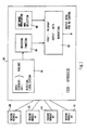
- Fig.1 ist ein schematisches Blockdiagramm und zeigt den Grundaufbau einer Vorrichtung zur Erkennung und Identifizierung von Fehlern an Sensoren und zur Rekonfiguration der Sensoren bei Auftreten von Fehlern.1 is a schematic block diagram and shows the basic structure of a device for detecting and identifying errors in sensors and for reconfiguring the sensors when errors occur.
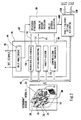
- Fig.2 ist ein schematisches Blockdiagramm der Vorrichtung von Fig.1 und zeigt im einzelnen die verschiedenen Mittel zur Erkennung und Identifizierung von Fehlern von Sensoren, die hier als zweiachsige Kreisel und Beschleunigungsmesser dargestellt sind.FIG. 2 is a schematic block diagram of the device of FIG. 1 and shows in detail the various means for detecting and identifying errors in sensors, which are shown here as two-axis gyroscopes and accelerometers.
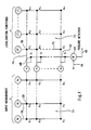
- Fig.3 veranschaulicht die Mehrheitsbetrachtung bei den Sensoren von Fig.2.FIG. 3 illustrates the majority consideration for the sensors of FIG. 2.
- Fig.4 zeigt ein Netzwerk durch welches der Paritätsvektor, die Detektionsfunktion und die Lokalisierungsfunktionen gebildet werden.4 shows a network through which the parity vector, the detection function and the localization functions are formed.
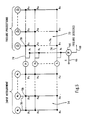
- Fig.5 zeigt ein Netzwerk ähnlich Fig.4 zur Erkennung und Identifizierung von zweiachsigen Fehlern, wie sie bei zweiachsigen, dynamisch abgestimmten Kreiseln zu erwarten sind.5 shows a network similar to FIG. 4 for the detection and identification of biaxial errors, as can be expected with biaxial, dynamically tuned gyroscopes.
- Fig.6 zeigt schematisch den Aufbau der Mittel zur Entscheidungsfindung über defekte und funktionsfähige Sensoren.6 shows schematically the structure of the means for making decisions about defective and functional sensors.
- Fig.7 ist ein Venn-Diagramm zur Erläuterung einer Möglichkeit der Entscheidungsfindung in den entscheidungsfindenden Mitteln von Fig.6.Fig. 7 is a Venn diagram for explaining a possibility of decision making in the decision-making means of Fig. 6.
- Fig.8 ist eine Logikschaltung zur Realisierung der Verknüpfung nach dem Venn-Diagramm von Fig.7.Fig. 8 is a logic circuit for realizing the link according to the Venn diagram of Fig. 7.
- Fig.9 veranschaulicht die Erzeugung der Ausgangsdaten.Fig. 9 illustrates the generation of the output data.
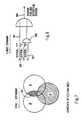
Bei der Ausführung nach Fig.1 sind vier identische Kanäle vorgesehen, die als Sensor-Module 10, 12, 14 und 16 bezeichnet werden. Wie aus Fig.2 erkennbar ist, enthält jedes Sensor-Modul einen zweiachsigen, elektrisch gefesselten, dynamisch abgestimmten Kreisel 18,20,22 und 24 und einen Beschleunigungsmesser 26, 28, 30 und 32. Die Anordnung entspricht der in der DE-A1-36 34 023 beschriebenen Ausführung.In the embodiment according to FIG. 1, four identical channels are provided, which are referred to as
Die Information von allen vier Sensor-Modulen 10,12,14 und 16 wird auf eine Einheit 34 zur Fehlererkennung, Fehleridentifizierung und Sensorrekonfiguration gegeben. Diese Einheit 34 erfüllt die folgenden Funktionen: Die Einheit 34 erkennt und identifiziert "Hard Failures", also den vollständigen Ausfall von Sensoren, sowie "Midvalue Failures" und "Soft Failures". Das ist durch Block 36 dargestellt. Die Einheit 34 fällt eine Entscheidung darüber, welcher Sensor als fehlerhaft anzusehen ist. Das ist durch Block 38 dargestellt. Weiterhin enthält die Einheit 34 Mittel 40 zur Überwachung der Software. Diese Mittel sind Gegenstand der Patentanmeldung P 39 23 432.0 und daher hier nicht näher beschrieben. Die Statusinformation von den Blöcken 38 und 40 ist auf Rekonfigurationsmittel 42 zur fehlertoleranten Erzeugung von Ausgangsdaten aufgeschaltet. Diese Ausgangsdaten dienen z.B. in der in der DE-A1-36 34 023 beschriebenen Weise zur Flugregelung und zur Erzeugung einer Kurs- und Lagereferenz.The information from all four
In Fig.2 sind die verschiedenen Stufen der Fehlererkennung und Fehleridentifizierung gemäß Block 36 von Fig.1 im einzelnen dargestellt.The various stages of error detection and error identification according to block 36 of FIG. 1 are shown in detail in FIG.
Es erfolgt zunächst eine Selbstüberwachung jedes einzelnen Sensors durch in den Sensor selbst eingebaute Prüfeinrichtungen. Es kann beispielsweise geprüft werden, ob ein Kreisel Strom erhält oder ob der Kreisel läuft, ob der Fesselkreis geschlossen ist, ob überhaupt ein Signal geliefert wird usw. Diese Selbstüberwachung ist durch Block 44 in Fig.2 dargestellt. Block 44 erhält Signale von den Überwachungseinrichtungen an den Sensoren selbst über Eingänge 46. Diese Selbstüberwachung von Sensoren ist an sich allgemein bekannt und daher hier nicht im einzelnen beschrieben.Each individual sensor is initially self-monitored by test devices built into the sensor itself. For example, it can be checked whether a gyro is receiving power or whether the gyro is running, whether the captive circuit is closed, whether a signal is being delivered, etc. This self-monitoring is represented by
An die geschilderte Selbstüberwachung gemäß Block 44 schließt sich eine Plausibilitätsprüfung an. Es wird geprüft, ob die von den Sensoren 18,20,22,24, 26,28,30 und 32 über die Leitungen 48 erhaltenen Signale beispielsweise mit den dynamischen Eigenschaften des Flugzeugs vereinbar sind. Es können so Störsignale eliminiert werden. Diese Plausibilitätsprüfung ist durch einen Block 50 dargestellt.A plausibility check follows the self-monitoring described in
Der nächste Überwachungsschritt ist eine Mehrheitsbetrachtung. Diese ist in Fig.2 durch Block 52 dargestellt. Bei üblicher Mehrheitsbetrachtung ("Voting Monitoring") sind drei identische Sensoren vorgesehen. Ein Sensor wird als fehlerhaft angesehen, wenn die beiden übrigen Sensoren innerhalb bestimmter Schwellwerte übereinstimmende Signale liefern und das Signal des betreffenden Sensors von diesen Signalen deutlich abweicht. Dieses Verfahren bietet Schwierigkeiten, wenn die Sensoren nicht nominell gleiche Signale liefern sondern beispielsweise Drehgeschwindigkeiten um verschiedene Eingangsachsen, wie das im vorliegenden Fall mit den Kreiseln 18,20,22 und 24 der Fall ist, oder Beschleunigungen längs unterschiedlicher Achsen wie die Beschleunigungsmesser 26,28,30 und 32. Die schon erwähnte DE-A1-36 40 023 liefert eine Lösung dieses Problems für eine spezielle geometrische Anordnung der Sensoren.The next monitoring step is a majority assessment. This is represented by
Es hat sich gezeigt, daß ein Kriterium für eine Mehrheitsbetrachtung für beliebig angeordnete zweiachsige Kreisel durch die Bedingung erhalten werden kann:
1/ (h ixh j)*< (mix g ix-mjxg jx)+miy g iy-mjy g jy) ; ·ωτ₋ h ixh j» < Eij
Darin sind:
mix,miy die Meßsignale des i-ten Kreisels um dessen x-bzw. y-Eingangsachse,
g ix,g iy die Einheitsvektoren in Richtung der x-Eingangsachse bzw. der y-Eingangsachse des i-ten Kreisels,
h i der Einheitsvektor in Richtung der Drallachse des i-ten Kreisels,
Eij vorgegebene Schwellwerte,
< a,b > das skalare Produkt von Vektoren a und b,
(axb) das Vektorprodukt der Vektoren a und b.It has been shown that a criterion for a majority consideration for arbitrarily arranged biaxial gyros can be obtained by the condition:
1 / ( h i x h j ) * <(m ix g ix -m jx g jx ) + m iy g iy -m jy g jy ); · Ωτ₋ h i x h j »<E ij
In it are:
m ix , m iy the measurement signals of the i-th gyro around its x or. y input axis,
g ix , g iy the unit vectors in the direction of the x input axis or the y input axis of the i-th gyro,
h i is the unit vector in the direction of the swirl axis of the i-th gyroscope,
E ij predetermined threshold values,
< a , b > the scalar product of vectors a and b ,
( a x b ) the vector product of vectors a and b .
Dieses Kriterium wird auf alle möglichen Kombinationen von Paaren von Kreiseln 18,20,22 und 24 oder -allgemeiner-Sensor-Moduln 10,12,14 und 16 angewandt. Daraus ergibt sich ein "Eij-Status", der angibt, für welche Paare von Sensor-Moduln die Schwellwerte überschritten werden. Aus diesem Eij-Status läßt sich ein defektes Sensor-Modul bestimmen. Nach diesem Prinzip arbeitet die Mehrheitsbetrachtung gemäß Block 52. In Fig.3 ist das noch einmal gesondert dargestellt. Die mix und miy werden von dem Meßvektor m geliefert. Die Vektoren g ix,g iy und h i sind aus der Geometrie der Anordnung bekannt und gespeichert.This criterion is applied to all possible combinations of pairs of
Der nächste Schritt dient dazu, auch "Midvalue" und "Soft Failures" zu erkennen. Dieser Schritt ist in Fig.2 durch einen Block 54 dargestellt.The next step is to identify "midvalue" and "soft failures". This step is represented by a
Hierzu wird für das vorliegende System eine "Meßmatrix" H bestimmt, welche alle von den Sensoren gelieferten Meßgrößen, die zu einem "Meßvektor" m zusammengefaßt werden, mit allen für die Regelung, hier für die Flugregelung, benötigten Zustandsgrößen verknüpft. Im vorliegenden Falle sind das die insgesamt acht Signale mix und miy der Kreisel 18,20,22 und 24 und die Signale der Beschleunigungsmesser 26,28,30 und 32. Die ausgegebenen Zustandsgrößen sind die Drehgeschwindigkeiten p,q,r um die flugzeugfesten Achsen und die Beschleunigungen ax,ay,az. Die Elemente der Meßmatrix enthält im vorliegenden Beispiel geometrische Größen. Die Meßmatrix kann aber auch physikalische Größen enthalten, wenn noch andere Sensoren, beispielsweise ein Doppler-Radar oder ein Laserkreisel, zur Bildung von Zustandsgrößen Herangezogen werden. Es wird nun -a priori- eine Matrix P beispielsweise wie folgt berechnet:
P = (I - H(H T H)⁻¹H T) = [v₁v₂...v n].
Die Spaltenvektoren dieser Matrix P mit den Komponenten p₁₁,p₁₂,..pm1; p₂₁,p₂₂,..pm2; ... p1n,p2n..pmn bilden "Validierungsvektoren" v i, von denen jeder einem Element des Meßvektors m zugeordnet ist. Diese Validierungsvektoren sind gespeichert.For this purpose, a "measurement matrix" H is determined for the present system, which links all the measurement quantities supplied by the sensors, which are combined to form a "measurement vector" m , with all the state quantities required for the control, here for the flight control. In the present case, these are the total of eight signals m ix and m iy from the
P = ( I - H ( H T H ) ⁻¹ H T ) = [ v ₁
The column vectors of this matrix P with the components p₁₁, p₁₂, .. p m1 ; p₂₁, p₂₂, .. p m2 ; ... p 1n , p 2n ..p mn form "validation vectors" v i , each of which is assigned to an element of the measurement vector m . These validation vectors are saved.
Die Matrix P ist eine mxn-Matrix mit m<n. Entsprechend sind die Validierungsvektoren von der Ordnung m<n. Es gibt n solche Validierungsvektoren.The matrix P is an mxn matrix with m <n. Accordingly, the validation vectors are of the order m <n. There are n such validation vectors.
Es wird nun in einem Rechner jeder Validierungsvektor v i mit der zugehörigen Komponente mi des Meßvektors m multipliziert. Das ergibt einen "Paritätsvektor" v mit den Komponenten[p₁,p₂,...pm].
Für die einzelnen Komponenten des Paritätsvektors ergibt sich damit:
p₁ = p₁₁m₁ + p₁₂m₂ +...p1mmm
p₂ = p₂₁m₁ + p₂₂m₂ +...p2mmm
usw. Dieser Paritätsvektor ist ein Element des Paritätsraumes, der das orthogonale Komplement des Signalraumes ist.This results for the individual components of the parity vector:
p₁ = p₁₁m₁ + p₁₂m₂ + ... p 1m m m
p₂ = p₂₁m₁ + p₂₂m₂ + ... p 2m m m
etc. This parity vector is an element of the parity space, which is the orthogonal complement of the signal space.
Fig.4 zeigt schematisch die Bildung des Paritätsvektors. An dem Netzwerk 54 liegen an Eingängen 56 die Komponenten des Meßvektors m, also die Meßgrößen m₁,m₂..mn, an. Diese Komponenten werden in den Knotenpunkten 58, die Multiplizierglieder darstellen können, jeweils mit den dort angegebenen Elementen der Matrix P oder Komponenten des zugehörigen Validierungsvektors v i multipliziert, beispielsweise m₂ mit p₁₂. Die Produkte werden nach rechts hin aufsummiert und liefern die Komponenten P₁..pm des Paritätsvektors v.4 shows schematically the formation of the parity vector. Lie on the
Es wird jetzt eine "Detektionsfunktion" DF gebildet. Eine solche Detektionsfunktion DF ist das skalare Produkt des Paritätsvektors mit sich selbst:
DF = < v;v >.A "detection function" DF is now formed. Such a detection function DF is the scalar product of the parity vector with itself:
DF = <v; v >.
Das ist in Fig.4 durch Multiplizierglieder 60 dargestellt, an denen die Komponenten p₁, p₂ usw. des Paritätsvektors liegen und die diese Komponenten jeweils mit sich selbst multiplizieren und so p₁²,P₂² usw. liefern. Diese Quadrate werden längs der vertikalen Verbindung 62 aufsummiert und liefern DF, wie durch Kreis symbolisiert ist. Die Detektionsfunktion DF wird mit einem Schwellwert E verglichen, der auf einen Eingang 66 aufgeschaltet ist. Wenn die Detektionsfunktion DF diesen Schwellwert E überschreitet, wird an einem Ausgang 68 ein Fehler signalisiert.This is shown in Fig.4 by
In diesem Falle werden "Lokalisierungsfunktionen" LFi gebildet. Das ist im rechten Teil von Fig.4 dargestellt.In this case, "localization functions" LF i are formed. This is shown in the right part of Fig.4.
Zur Bildung der Lokalisierungsfunktionen werden die Komponenten des Paritätsvektors p₁, p₂, ... pn mit Komponenten p₁₁, p₁₂ usw. der Validierungsvektoren v i multipliziert. Die Knotenpunkte 70 des Netzwerkes 72 können als Multiplizierglieder betrachtet werden, die wieder die an Eingängen 74 dieses Netzwerkes 72 anliegenden Komponenten p₁, p₂ ... pn des Paritätsvektors v mit den danebenstehenden Matrixelementen p₁₁ usw. multiplizieren. Die erhaltenen Produkte werden längs der vertikalen Verbindungen 76 aufsummiert und liefern die Lokalisierungsfunktionen LFi.To form the localization functions, the components of the parity vector p₁, p₂, ... p n are multiplied by components p₁₁, p₁₂ etc. of the validation vectors v i . The
Es wird nun die maximale Lokalisierungsfunktion
LFj = max LFi , i=1,2...n
aufgesucht. Diese charakterisiert den fehlerhaften Sensor.It now becomes the maximum localization function
LF j = max LF i , i = 1,2 ... n
visited. This characterizes the faulty sensor.
Bei Verwendung von dynamisch abgestimmten Kreiseln, wie sie in dem vorliegenden Ausführungsbeispiel als Sensoren vorgesehen sind, besteht eine gewisse Wahrscheinlichkeit dafür, daß ein Fehler gleichzeitig auf beiden Eingangsachsen des Kreisels auftritt. Fig.5 zeigt eine Anordnung, welche diesem Sachverhalt Rechnung tragen kann.When using dynamically tuned gyros, such as are provided as sensors in the present exemplary embodiment, there is a certain probability that an error will occur simultaneously on both input axes of the gyro. 5 shows an arrangement which can take this fact into account.
Im linken Teil von Fig.5 wird in der gleichen Weise wie in Fig.4 der Paritätsvektor v aus dem Meßvektor m und den Validierungsvektoren v i gebildet. Auch die Bildung der Detektionsfunktion DF und der Vergleich der Detektionsfunktion mit einem Schwellwert zum Erkennen eines Fehlers ist die gleiche wie in Fig.4. Entsprechende Teile sind in Fig.5 mit den gleichen Bezugszeichen versehen wie in Fig.4.In the left part of FIG. 5, the parity vector v is formed from the measurement vector m and the validation vectors v i in the same way as in FIG. The formation of the detection function DF and the comparison of the detection function with a threshold value for recognizing an error is the same as in FIG. 4. Corresponding parts are given the same reference numerals in FIG. 5 as in FIG. 4.
Es werden auch Funktionen durch Multiplikation der Komponenten pi des Paritätsvektors v mit den Elementen der Matrix P gebildet. In Fig.5 werden, wie in Fig.4, waagerecht die Komponenten des Paritätsvektors v, z.B. p₁ mit den Matrixelementen p₁₁,p₁₂, ... p1n multipliziert und längs der vertikalen Verbindung des Netzwerkes 72 aufsummiert. Auch insofern stimmt die Anordnung von Fig.5 mit der Anordnung von Fig.4 überein, und auch hier sind entsprechende Teile mit den gleichen Bezugszeichen versehen wie in Fig.4. Die Summation längs der vertikalen Verbindungen des Netzwerkes liefern jedoch nicht unmittelbar die Lokalisierungsfunktionen sondern Funktionen Δ₁, Δ₂, Δ₃... Δn. Aus den Δi mit 1≦i≦n werden Lokalisierungsfunktionen von der Form
LF(k,l) = Δk v k + Δl v l ²
mit 1≦l≦n und 1≦k≦n gebildet, wobei die k und l stets den beiden Eingangsachsen eines dynamisch abgestimmten Kreisels zugeordnet sind. Die Δi sind ein Maß für die Projektion eines Fehlers auf die Validierungsvektoren v i. Es wird die maximale Lokalisierungsfunktion
LF( i,j) = max LF(k,l)
aufgesucht. Aus dieser maximalen Lokalisierungsfunktion kann auf einen Defekt des zugeordneten Sensors mit den Eingangsachsen i und j geschlossen werden.Functions are also formed by multiplying the components p i of the parity vector v by the elements of the matrix P. In Fig.5, as in Fig.4, the components of the parity vector v , for example p₁, are multiplied horizontally by the matrix elements p₁₁, p₁₂, ... p 1n and summed along the vertical connection of the
LF (k, l) = Δ k v k + Δ l v l ²
formed with 1 ≦ l ≦ n and 1 ≦ k ≦ n, whereby the k and l are always assigned to the two input axes of a dynamically tuned gyro. The Δ i are a measure of the projection of an error onto the validation vectors v i . It becomes the maximum localization function
LF (i, j) = max LF (k, l)
visited. From this maximum localization function, a defect of the assigned sensor with the input axes i and j can be concluded.
Der Statusausgang 80 der Selbstüberwachung 44, der Statusausgang 82 der Plausibilitätsprüfung 50, der Statusausgang der Mehrheitsbetrachtung 52 und der durch Vergleich des Paritätsvektors mit einem Schwellwert, dargestellt durch Block 84, erhaltene Statusausgang 86 sind auf die entscheidungsfindenden Mittel 88 geschaltet. Die entscheidungsfindenden Mittel liefern Statusinformation darüber, welche der Sensoren 18 bis 32 als fehlerbehaftet und welche als funktionierend angesehen werden sollen.The
Fig.6 zeigt schematisch die Funktion dieser entscheidungsfindenden Mittel. Die entscheidungsfindenden Mittel berücksichtigen, welchen Grad von Zuverlässigkeit die Statusaussagen der verschiedenen Prüfschritte besitzen.Fig. 6 shows schematically the function of these decision-making means. The decision-making means take into account the degree of reliability of the status statements of the various test steps.
Es werden zunächst Regeln für Voraussetzungen und Folgen (wenn, dann) aufgestellt. Das ist in Fig.6 durch Block 90 dargestellt. Aufgrund dieser Regeln ergibt sich ein Inferenznetz, das durch Block 92 angedeutet ist. Die so erhaltenen Entscheidungen sind selten sicher. Es schließen sich daher an die auf den Regeln für Voraussetzungen und Folgen basierenden Entscheidungsfindung Bestimmtheitsrechnungen (certainty computations) an. Das ist durch Block 94 dargestellt. Für diese Bestimmtheitsrechnungen können bekannte Techniken angewandt werden. Es muß jedoch für jede individuelle Anwendung ein spezielles Inferenznetz vorgesehen sein.First rules for requirements and consequences (if, then) are drawn up. This is represented by
Aus dem Ergebnis der Bestimmtheitsrechnung wird eine Entscheidung gefunden, welcher Sensor als fehlerhaft angesehen wird (Block 96) und welcher Sensor brauchbar ist (Block 98). Wie dargestellt, liefern die entscheidungsfindenden Mittel 32 Statusinformation, welche die brauchbaren Sensoren angibt.From the result of the determination of the determination, a decision is made as to which sensor is considered defective (block 96) and which sensor is usable (block 98). As shown, the decision-making means 32 provide status information indicating the sensors that can be used.
Ein vereinfachtes Beispiel für eine solche Entscheidungsfunktion ist nachstehend unter Bezugnahme auf Fig.7 und 8 erläutert:A simplified example of such a decision function is explained below with reference to FIGS. 7 and 8:
Die einzelnen Elemente der Einheit 36 in Fig.2 erzeugen einen Fehlererkennungs-Status wie folgt:
- Die Selbstüberwachung 44 (BITE) kombiniert mit der Plausibilitätsprüfung 50 erzeugen an dem Status-Ausgang 82 einen Status "B".
- Die Mehrheitsbetrachtung 52 erzeugt an dem Status-Ausgang 84 einen Status "V".
- Die Prüfung 54 aufgrund des Paritätsvektors erzeugt an einem Status-Ausgang 86 einen Status "P".The individual elements of the
The self-monitoring 44 (BITE) combined with the
The
The
Das folgende Kriterium wird für die kombinatorische Korrelation der mehrfachen Statusinformation der Einheit 36 festgelegt:
- Ein Fehler des Systems wird erkannt, wenn entweder der Status "P" oder aber der Status "B" und gleichzeitig der Status "V" einen Fehler signalisiert.The following criterion is determined for the combinatorial correlation of the multiple status information of the unit 36:
- An error in the system is recognized if either the status "P" or the status "B" and at the same time the status "V" signals an error.
Das ist in Fig.7 an einem Venn-Diagramm verdeutlicht: Ein Fehler wird entdeckt in der gesamten Menge "P" und zuzüglich in der Schnittmenge 100 der Mengen "B" und "V". In Fig.8 ist das als Logikschaltung dargestellt, wobei "wahr" oder "unwahr" durch Signale L oder H an den drei Eingängen 82,84 und 86 der entscheidungsfindenden Mittel 38 signalisiert sind. Die Eingänge 82 und 84 liegen an den beiden Eingängen eines UND-Gliedes 102. Der Ausgang 104 des UND-Gliedes 102 und der Eingang 86 liegen an den Eingängen eines ODER-Gliedes 106. Der Ausgang 106 liefert ein Fehlererkennungssignal.This is illustrated in FIG. 7 on a Venn diagram: A fault is discovered in the entire set "P" and plus in the
Die kombinierte Wahrscheinlichkeit der Fehlererkennung kann berechnet werden als
Pr(det) = Pr(P) + Pr(BV)*(1-Pr(P)),
wenn Pr(P) die Wahrscheinlichkeit der Fehlererkennung mittels des Elements des Paritätsvektors ist und Pr(BV) die kombinierte Wahrscheinlichkeit der Fehlererkennung mittels der Selbstüberwachung und der Mehrheitsbetrachtung ist.The combined probability of error detection can be calculated as
Pr (det) = Pr (P) + Pr (BV) * (1-Pr (P)),
if Pr (P) is the probability of error detection using the element of the parity vector and Pr (BV) is the combined probability of error detection using self-monitoring and majority consideration.
Die Fehlerstatussignale der verschiedenen Sensoren werden von den entscheidungsfindenden Mitteln 38 über Ausgang 108 auf einen fehlertoleranten, optimalen Schätzer 110 gegeben. Der Schätzer 110 erzeugt aus den als zutreffend angesehenen Sensorsignalen Schätzwerte der Zustandsgrößen.The error status signals of the various sensors are given by decision-making means 38 via
Die Funktion dieses Schätzers 110 ist in Fig.9 für den vorliegenden Fall der Trägheitssensoren für die Flugregelung schematisch dargestellt.The function of this
Aus der Statusinformation vom Ausgang 108 der entscheidungsfindenden Mittel wird abgeleitet, daß z.B. die i-te Meßachse oder der Kreisel mit den Eingangsachsen (i,j) defekt ist (Block 112). Dementsprechend werden die Meßgrößen mi bzw. mi und mj von der weiteren Signalverarbeitung ausgeschlossen. Das ist durch Block 114 dargestellt.It is derived from the status information from the
Der Vektor der für die Flugregelung benötigten Zustandsgrößen sei ω. Dieser Vektor hängt mit dem Meßvektor m durch eine lineare Beziehung
ω = M*m.The vector of the state variables required for flight control is ω . This vector depends on the measurement vector m through a linear relationship
ω = M * m .
Als nächster Schritt erfolgt eine Rekonfiguration der Matrix M, so daß dem Wegfall eines Sensors oder mehrerer Sensoren Rechnung getragen wird. Das ist durch Block 116 dargestellt. Mit der rekonfigurierten Matrix M werden Schätzwerte für den Vektor ω gebildet. Das ist durch Block 118 dargestellt. Die so erhaltenen Schätzwerte werden auf einen Ausgang 120 gegeben und auf den Flugregler aufgeschaltet.The next step is a reconfiguration of the matrix M , so that the omission of one or more sensors is taken into account. This is represented by
Die Matrix M setzt jeweils die verfügbaren, redundanten Messungen in beste Schätzungen orthogonaler Drehgeschwindigkeiten und Beschleunigungen um. Für die optimale Schätzung der Drehgeschwindigkeiten können bewährte Methoden der kleinsten Fehlerquadrate dienen.The matrix M converts the available, redundant measurements into best estimates of orthogonal rotational speeds and accelerations. Proven methods of least squares can be used to optimally estimate the rotational speeds.
Claims (7)
m = H x + ε
verknüpft sind, wobei m ein Vektor der Meßgrößen, x ein Vektor der Zustandsgrößen und H die Meßmatrix ist und wobei die Ordnung von m größer ist als die Ordnung von x,
gekennzeichnet durch die Verfahrensschritte
P = [v₁ v₂...v n]
DF = < v v >
als skalares Produkt des Pariätsvektors mit sich selbst, und Prüfung, ob diese Detektionsfunktion größer oder kleiner als ein vorgegebener Grenzwert ist, wobei das Überschreiten dieses Grenzwertes das Vorhandensein eines Fehlers signalisiert,
m = H x + ε
are linked, where m is a vector of the measured variables, x is a vector of the state variables and H is the measurement matrix and the order of m is greater than the order of x ,
characterized by the process steps
P = [ v ₁ v ₂ ... v n ]
DF = < v v >
as a scalar product of the parity vector with itself, and checking whether this detection function is greater or less than a predetermined limit value, exceeding this limit signaling the presence of an error,
LF(k,l) = / Δk v k + Δl v l/²
mit 1≦l≦n und 1≦k≦n gebildet werden, wobei die k und l jeweils Paaren von zusammengehörigen Sensorsignalen zugeordnet sind, bei denen das gleichzeitige Auftreten von Fehlern wahrscheinlich ist, und die Δi ein Maß für die Projektion eines normierten Fehlervektors auf die betreffenden Validierungsvektoren ist, und
LF (k, l) = / Δ k v k + Δ l v l / ²
are formed with 1 ≦ l ≦ n and 1 ≦ k werden n, the k and l being assigned to pairs of related sensor signals in which the simultaneous occurrence of errors is likely, and the Δ i is a measure of the projection of a normalized error vector to the validation vectors concerned, and
- einer Funktionsüberwachung,
- einer Plausibilitätsprüfung, in welcher geprüft wird, ob die jeweils erhaltenen Meßwerte sich in Übereinstimmung mit den dynamischen Eigenschaften des Systems befinden,
- einer Mehrheitsbetrachtung, bei welcher die aus den Signalen verschiedener Sensoren erhaltenen Zustandsgrößen miteinander verglichen werden, wobei Sensoren, deren Meßgrößen zu Zustandsgrößen führen, welche von den aus der Mehrheit der anderen Sensoren gewonnenen Zustandsgrößen deutlich abweichen, als fehlerhaft angesehen werden,
- der Überwachung anhand des Paritätsvektors und des Vergleichs mit Schwellwerten,
- function monitoring,
a plausibility check, in which it is checked whether the measured values obtained in each case are in accordance with the dynamic properties of the system,
a majority analysis, in which the state variables obtained from the signals of different sensors are compared with one another, sensors whose measurement variables leading to state variables which differ significantly from the state variables obtained from the majority of the other sensors being regarded as faulty,
- monitoring based on the parity vector and comparison with threshold values,
1/ h ixh j)*< (mix g ix-mjxg jx)+miy g iy-mjy g jy) ; < h ixh j» < Eij
wobei
mix,miy die Meßsignale des i-ten Kreisels um dessen x- bzw. y-Eingangsachse,
g ix,g iy die Einheitsvektoren in Richtung der x-Eingangsachse bzw. der y-Eingangsachse des i-ten Kreisels,
h i der Einheitsvektor in Richtung der Drallachse des i-ten Kreisels,
Eij vorgegebene Schwellwerte,
< a,b > das skalare Produkt von Vektoren a und b und
(axb) das Vektorprodukt der Vektoren a und b sind,
1 / h i x h j ) * <(m ix g ix -m jx g jx ) + m iy g iy -m jy g jy ); < h i x h j »<E ij
in which
m ix , m iy the measurement signals of the i-th gyro about its x or y input axis,
g ix , g iy the unit vectors in the direction of the x input axis or the y input axis of the i-th gyro,
h i is the unit vector in the direction of the swirl axis of the i-th gyroscope,
E ij predetermined threshold values,
< a , b > the scalar product of vectors a and b and
( a x b ) are the vector product of vectors a and b ,
m = H x + ε
verknüpft sind, wobei m ein Vektor der Meßgrößen, x ein Vektor der Zustandsgrößen und H die Meßmatrix ist und wobei die Ordnung von m größer ist als die Ordnung von x, zur Durchführung des Verfahrens nach Anspruch 1, gekennzeichnet durch
P = [v₁ v₂...v n]

DF = < v v >
als skalares Produkt des Pariätsvektors mit sich selbst, und Prüfung, ob diese Detektionsfunktion größer oder kleiner als ein vorgegebener Grenzwert ist, wobei das Überschreiten dieses Grenzwertes das Vorhandensein eines Fehlers signalisiert,
m = H x + ε
are linked, where m is a vector of the measured variables, x is a vector of the state variables and H is the measurement matrix and the order of m is greater than the order of x , for carrying out the method according to claim 1, characterized by
P = [ v ₁ v ₂ ... v n ]
DF = < v v >
as a scalar product of the parity vector with itself, and checking whether this detection function is greater or less than a predetermined limit value, exceeding this limit signaling the presence of an error,
LF(k,l) = / Δk v k + Δl v l/²
mit 1≦l≦n und 1≦k≦n eingerichtet sind, wobei die k und l jeweils Paaren von zusammengehörigen Sensorsignalen zugeordnet sind, bei denen das gleichzeitige Auftreten von Fehlern wahrscheinlich ist, und die Δi ein Maß für die Projektion eines normierten Fehlervektors auf die betreffenden Validierungsvektoren ist, und
LF (k, l) = / Δ k v k + Δ l v l / ²
are set up with 1 ≦ l ≦ n and 1 ≦ k ≦ n, where the k and l are each assigned to pairs of related sensor signals in which the simultaneous occurrence of errors is likely, and the Δ i is a measure of the projection of a normalized error vector to the validation vectors concerned, and
- Mittel zur Funktionsüberwachung der Sensoren vorgesehen sind sowie
- Mittel zur Plausibilitätsprüfung der Sensorsignale zur Prüfung, ob die jeweils erhaltenen Meßwerte sich in Übereinstimmung mit den dynamischen Eigenschaften des Systems befinden,
- Mittel zur Durchführung einer Mehrheitsbetrachtung, bei welcher die aus den Signalen verschiedener Sensoren erhaltenen Zustandsgrößen miteinander verglichen und werden, wobei Sensoren, deren Meßgrößen zu Zustandsgrößen führen, welche von den aus der Mehrheit der anderen Sensoren gewonnenen Zustandsgrößen deutlich abweichen, als fehlerhaft angesehen werden,
- die Mittel zur Überwachung der Sensorsignale anhand des Paritätsvektors und des Vergleichs mit Schwellwerten,
- Means for function monitoring of the sensors are provided as well
Means for checking the plausibility of the sensor signals to check whether the measured values obtained in each case are in accordance with the dynamic properties of the system,
Means for carrying out a majority analysis, in which the state variables obtained from the signals of different sensors are compared with one another, sensors, the measured variables of which lead to state variables which differ significantly from the state variables obtained from the majority of the other sensors, are regarded as faulty,
the means for monitoring the sensor signals on the basis of the parity vector and the comparison with threshold values,
Applications Claiming Priority (2)
| Application Number | Priority Date | Filing Date | Title |
|---|---|---|---|
| DE3929404 | 1989-09-05 | ||
| DE3929404A DE3929404A1 (en) | 1989-09-05 | 1989-09-05 | METHOD AND DEVICE FOR DETECTING AND IDENTIFYING ERRORS ON SENSORS |
Publications (3)
| Publication Number | Publication Date |
|---|---|
| EP0416370A2 true EP0416370A2 (en) | 1991-03-13 |
| EP0416370A3 EP0416370A3 (en) | 1992-05-20 |
| EP0416370B1 EP0416370B1 (en) | 1995-11-22 |
Family
ID=6388638
Family Applications (1)
| Application Number | Title | Priority Date | Filing Date |
|---|---|---|---|
| EP90116029A Expired - Lifetime EP0416370B1 (en) | 1989-09-05 | 1990-08-22 | Method and device for detecting and indentifying sensor errors |
Country Status (4)
| Country | Link |
|---|---|
| EP (1) | EP0416370B1 (en) |
| AT (1) | ATE130687T1 (en) |
| DE (2) | DE3929404A1 (en) |
| ES (1) | ES2081883T3 (en) |
Cited By (7)
| Publication number | Priority date | Publication date | Assignee | Title |
|---|---|---|---|---|
| EP0675420A1 (en) * | 1994-03-28 | 1995-10-04 | Bodenseewerk Gerätetechnik GmbH | Monitoring device for monitoring the safety of airplanes |
| EP0720004A3 (en) * | 1994-12-27 | 1996-08-07 | Litef Gmbh | |
| WO1996028710A1 (en) * | 1995-03-10 | 1996-09-19 | Siemens Aktiengesellschaft | Method of determining a reliability parameter for a responsive system, and such a system for signal processing |
| EP1020699A1 (en) * | 1998-12-15 | 2000-07-19 | Bodenseewerk Gerätetechnik GmbH | Missile |
| WO2001048571A1 (en) * | 1999-12-29 | 2001-07-05 | Aspen Technology, Inc. | Sensor validation method and apparatus |
| US6356857B1 (en) | 1998-08-17 | 2002-03-12 | Aspen Technology, Inc. | Sensor validation apparatus and method |
| CN110187503A (en) * | 2018-02-23 | 2019-08-30 | 罗德施瓦兹两合股份有限公司 | For searching the measuring instrument identifying system and method for particular measurement instrument |
Families Citing this family (9)
| Publication number | Priority date | Publication date | Assignee | Title |
|---|---|---|---|---|
| DE4241822C2 (en) * | 1992-12-11 | 1996-09-19 | Bosch Gmbh Robert | Circuit arrangement for error detection when evaluating sensor signals |
| DE4244014A1 (en) * | 1992-12-24 | 1994-07-07 | Bodenseewerk Geraetetech | Detection and identification of sensor errors e.g. for aircraft controller |
| JP3221184B2 (en) * | 1993-10-13 | 2001-10-22 | 株式会社日立製作所 | Failure diagnosis apparatus and method |
| US5615119A (en) * | 1995-06-07 | 1997-03-25 | Aurora Flight Sciences Corporation | Fault tolerant automatic control system utilizing analytic redundancy |
| US6085127A (en) | 1997-03-18 | 2000-07-04 | Aurora Flight Sciences Corporation | Fault tolerant automatic control system utilizing analytic redundancy |
| US6539290B1 (en) | 1995-06-07 | 2003-03-25 | Dabulamanzi Holdings, Llc | Method, apparatus and design procedure for controlling multi-input, multi-output (MIMO) parameter dependent systems using feedback LTI'zation |
| DE102004037352B4 (en) * | 2004-07-30 | 2008-06-26 | Eads Deutschland Gmbh | Method for monitoring a permissible confidence of a measurand of a dynamic system |
| US7805245B2 (en) * | 2007-04-18 | 2010-09-28 | Honeywell International Inc. | Inertial measurement unit fault detection isolation reconfiguration using parity logic |
| US20230249845A1 (en) * | 2022-02-07 | 2023-08-10 | Hamilton Sundstrand Corporation | Artificial intelligence and/or machine learning (ai/ml) monitor systems |
Family Cites Families (7)
| Publication number | Priority date | Publication date | Assignee | Title |
|---|---|---|---|---|
| US3984672A (en) * | 1974-12-05 | 1976-10-05 | Control Systems Research, Inc. | Solid state translator |
| US4268354A (en) * | 1978-10-12 | 1981-05-19 | Westinghouse Electric Corp. | Nuclear reactor in core flux mapping system |
| US4580234A (en) * | 1982-08-02 | 1986-04-01 | Nippon Business Consultant Co., Ltd. | Measurement system of enhanced reliability |
| US4622667A (en) * | 1984-11-27 | 1986-11-11 | Sperry Corporation | Digital fail operational automatic flight control system utilizing redundant dissimilar data processing |
| US4787058A (en) * | 1985-09-13 | 1988-11-22 | Rockwell International Corporation | Synthetic quadrature generating apparatus |
| US4665748A (en) * | 1985-10-21 | 1987-05-19 | Sundstrand Data Control, Inc. | Automatic continuous nulling of angular rate sensor |
| DE3634023A1 (en) * | 1986-10-07 | 1988-04-21 | Bodenseewerk Geraetetech | INTEGRATED, REDUNDANT REFERENCE SYSTEM FOR FLIGHT CONTROL AND FOR GENERATING COURSE AND LOCATION INFORMATION |
-
1989
- 1989-09-05 DE DE3929404A patent/DE3929404A1/en not_active Withdrawn
-
1990
- 1990-08-22 AT AT90116029T patent/ATE130687T1/en active
- 1990-08-22 ES ES90116029T patent/ES2081883T3/en not_active Expired - Lifetime
- 1990-08-22 EP EP90116029A patent/EP0416370B1/en not_active Expired - Lifetime
- 1990-08-22 DE DE59009896T patent/DE59009896D1/en not_active Expired - Fee Related
Non-Patent Citations (3)
| Title |
|---|
| 1989 American Control Conference, Pittsburgh, USA, June 21-23, 1989, J. GERTLER ET AL: 'A Parallel Implementation of Model Based On-Line Failure Detection and Isolation', pages 2727-2731 * |
| AUTOMATISIERUNGSTECHNIK vol. 37, no. 8, August 1988, MUNICH, GERMANY pages 289 - 294; J. PROCK: 'Ein allgemeines Konzept zur On-line Messfehlererkennung in dynamischen Systemen mittels analytischer Redundanz' * |
| I.E.E.E. TRANSACTIONS ON INDUSTRY APPLICATIONS vol. 24, no. 5, October 1988, NEW YORK, USA pages 905 - 912; H. P. POLENTA ET AL: 'Microcomputer Based Fault Detection using Redundant Sensors' * |
Cited By (12)
| Publication number | Priority date | Publication date | Assignee | Title |
|---|---|---|---|---|
| EP0675420A1 (en) * | 1994-03-28 | 1995-10-04 | Bodenseewerk Gerätetechnik GmbH | Monitoring device for monitoring the safety of airplanes |
| US5710559A (en) * | 1994-03-28 | 1998-01-20 | Bodenseewerk Geratetechnik Gmbh | Flight safety monitoring device for aircraft with alarm |
| EP0720004A3 (en) * | 1994-12-27 | 1996-08-07 | Litef Gmbh | |
| US5661735A (en) * | 1994-12-27 | 1997-08-26 | Litef Gmbh | FDIC method for minimizing measuring failures in a measuring system comprising redundant sensors |
| WO1996028710A1 (en) * | 1995-03-10 | 1996-09-19 | Siemens Aktiengesellschaft | Method of determining a reliability parameter for a responsive system, and such a system for signal processing |
| US6012147A (en) * | 1995-03-10 | 2000-01-04 | Siemens Aktiengesellschaft | Method for determining a reliability parameter of a responsive system, and a corresponding signal processing system |
| US6356857B1 (en) | 1998-08-17 | 2002-03-12 | Aspen Technology, Inc. | Sensor validation apparatus and method |
| US6594620B1 (en) | 1998-08-17 | 2003-07-15 | Aspen Technology, Inc. | Sensor validation apparatus and method |
| EP1020699A1 (en) * | 1998-12-15 | 2000-07-19 | Bodenseewerk Gerätetechnik GmbH | Missile |
| WO2001048571A1 (en) * | 1999-12-29 | 2001-07-05 | Aspen Technology, Inc. | Sensor validation method and apparatus |
| CN110187503A (en) * | 2018-02-23 | 2019-08-30 | 罗德施瓦兹两合股份有限公司 | For searching the measuring instrument identifying system and method for particular measurement instrument |
| CN110187503B (en) * | 2018-02-23 | 2023-08-22 | 罗德施瓦兹两合股份有限公司 | Measuring instrument identification system and method for searching specific measuring instrument |
Also Published As
| Publication number | Publication date |
|---|---|
| EP0416370B1 (en) | 1995-11-22 |
| DE59009896D1 (en) | 1996-01-04 |
| DE3929404A1 (en) | 1991-03-07 |
| ATE130687T1 (en) | 1995-12-15 |
| ES2081883T3 (en) | 1996-03-16 |
| EP0416370A3 (en) | 1992-05-20 |
Similar Documents
| Publication | Publication Date | Title |
|---|---|---|
| EP0416370B1 (en) | Method and device for detecting and indentifying sensor errors | |
| DE102010047960B4 (en) | Sensor arrangement and method to use this | |
| DE10297009B4 (en) | Sensor fusion using self-evaluating process sensors | |
| EP0720004B1 (en) | FDIC-method for minimising measurement errors in a measurement arrangement with redundant sensors | |
| DE4436658B4 (en) | Device and method for troubleshooting | |
| DE102009061036B4 (en) | Residue generation apparatus and method for detecting erroneous transients, drifts or oscillations in the system behavior of a system of an aircraft, and aircraft | |
| EP0675420A1 (en) | Monitoring device for monitoring the safety of airplanes | |
| DE4100501A1 (en) | Detecting and identifying faults at sensors for state values - using association matrix giving optimal relationship between characteristic vectors and associated classification vectors | |
| DE102018116696A1 (en) | A method for generating normal state prediction data of a plant and apparatus using the same | |
| DE10135586A1 (en) | Computer-based reconfiguration method for compensation of sensor failures within a sensor system to increase the failure tolerance of a measurement system by initialization of new observers when a failure condition is noted | |
| WO2001043079A1 (en) | Method for recognition of faults on a motor vehicle | |
| EP2615418A2 (en) | Method for increasing the reliability of sensor systems | |
| DE102019124301A1 (en) | Device and method for ensuring the fail-safe function of an autonomous driving system | |
| EP3155374A1 (en) | Method and system for initializing a sensor fusion system | |
| EP3282399A1 (en) | Method for the improved detection of process anomalies of a technical installation and corresponding diagnostic system | |
| DE112019006789T5 (en) | WORK DETERMINATION DEVICE AND WORK DETERMINATION PROCEDURE | |
| DE102017201032A1 (en) | Redundant processor architecture | |
| DE102011106302B3 (en) | Method for determining measurement error of force moment sensor utilized in robotics, involves comparing determined sensor values with pseudo sensor values received by inverse transformation for determining measurement error of sensor | |
| DE102016114366B4 (en) | FAILSAFE REDUCED ORDER INERTIAL UNIT MEASURING SYSTEM | |
| DE102017222420A1 (en) | PROCESS FOR PLAUSIBILIZATION OF THE POWER SUPPLY OF AN ELECTRIC MOTOR | |
| DE102009012887B4 (en) | Method for checking incorrect installation of vehicle sensors | |
| WO2015149799A1 (en) | Stereo camera system | |
| DE4244014A1 (en) | Detection and identification of sensor errors e.g. for aircraft controller | |
| EP4147943A1 (en) | Measuring assembly | |
| DE102007020480B4 (en) | Method for checking a communication connection |
Legal Events
| Date | Code | Title | Description |
|---|---|---|---|
| PUAI | Public reference made under article 153(3) epc to a published international application that has entered the european phase |
Free format text: ORIGINAL CODE: 0009012 |
|
| AK | Designated contracting states |
Kind code of ref document: A2 Designated state(s): AT BE CH DE ES FR GB GR IT LI LU NL SE |
|
| PUAL | Search report despatched |
Free format text: ORIGINAL CODE: 0009013 |
|
| AK | Designated contracting states |
Kind code of ref document: A3 Designated state(s): AT BE CH DE ES FR GB GR IT LI LU NL SE |
|
| 17P | Request for examination filed |
Effective date: 19920731 |
|
| 17Q | First examination report despatched |
Effective date: 19931028 |
|
| GRAA | (expected) grant |
Free format text: ORIGINAL CODE: 0009210 |
|
| AK | Designated contracting states |
Kind code of ref document: B1 Designated state(s): AT BE CH DE ES FR GB GR IT LI LU NL SE |
|
| PG25 | Lapsed in a contracting state [announced via postgrant information from national office to epo] |
Ref country code: NL Free format text: LAPSE BECAUSE OF FAILURE TO SUBMIT A TRANSLATION OF THE DESCRIPTION OR TO PAY THE FEE WITHIN THE PRESCRIBED TIME-LIMIT Effective date: 19951122 Ref country code: GR Free format text: LAPSE BECAUSE OF FAILURE TO SUBMIT A TRANSLATION OF THE DESCRIPTION OR TO PAY THE FEE WITHIN THE PRESCRIBED TIME-LIMIT Effective date: 19951122 Ref country code: BE Effective date: 19951122 |
|
| REF | Corresponds to: |
Ref document number: 130687 Country of ref document: AT Date of ref document: 19951215 Kind code of ref document: T |
|
| REF | Corresponds to: |
Ref document number: 59009896 Country of ref document: DE Date of ref document: 19960104 |
|
| ET | Fr: translation filed | ||
| REG | Reference to a national code |
Ref country code: CH Ref legal event code: NV Representative=s name: TROESCH SCHEIDEGGER WERNER AG |
|
| ITF | It: translation for a ep patent filed |
Owner name: STUDIO JAUMANN |
|
| REG | Reference to a national code |
Ref country code: ES Ref legal event code: FG2A Ref document number: 2081883 Country of ref document: ES Kind code of ref document: T3 |
|
| GBT | Gb: translation of ep patent filed (gb section 77(6)(a)/1977) |
Effective date: 19960217 |
|
| NLV1 | Nl: lapsed or annulled due to failure to fulfill the requirements of art. 29p and 29m of the patents act | ||
| PG25 | Lapsed in a contracting state [announced via postgrant information from national office to epo] |
Ref country code: GB Effective date: 19960822 Ref country code: AT Effective date: 19960822 |
|
| PG25 | Lapsed in a contracting state [announced via postgrant information from national office to epo] |
Ref country code: SE Effective date: 19960823 Ref country code: ES Free format text: LAPSE BECAUSE OF THE APPLICANT RENOUNCES Effective date: 19960823 |
|
| PG25 | Lapsed in a contracting state [announced via postgrant information from national office to epo] |
Ref country code: LU Free format text: LAPSE BECAUSE OF NON-PAYMENT OF DUE FEES Effective date: 19960831 Ref country code: LI Effective date: 19960831 Ref country code: CH Effective date: 19960831 |
|
| PLBE | No opposition filed within time limit |
Free format text: ORIGINAL CODE: 0009261 |
|
| STAA | Information on the status of an ep patent application or granted ep patent |
Free format text: STATUS: NO OPPOSITION FILED WITHIN TIME LIMIT |
|
| 26N | No opposition filed | ||
| REG | Reference to a national code |
Ref country code: CH Ref legal event code: PL |
|
| GBPC | Gb: european patent ceased through non-payment of renewal fee |
Effective date: 19960822 |
|
| PG25 | Lapsed in a contracting state [announced via postgrant information from national office to epo] |
Ref country code: FR Effective date: 19970430 |
|
| EUG | Se: european patent has lapsed |
Ref document number: 90116029.1 |
|
| REG | Reference to a national code |
Ref country code: FR Ref legal event code: ST |
|
| PGFP | Annual fee paid to national office [announced via postgrant information from national office to epo] |
Ref country code: DE Payment date: 19991019 Year of fee payment: 10 |
|
| REG | Reference to a national code |
Ref country code: ES Ref legal event code: FD2A Effective date: 19991108 |
|
| PG25 | Lapsed in a contracting state [announced via postgrant information from national office to epo] |
Ref country code: DE Free format text: LAPSE BECAUSE OF NON-PAYMENT OF DUE FEES Effective date: 20010501 |
|
| PG25 | Lapsed in a contracting state [announced via postgrant information from national office to epo] |
Ref country code: IT Free format text: LAPSE BECAUSE OF NON-PAYMENT OF DUE FEES;WARNING: LAPSES OF ITALIAN PATENTS WITH EFFECTIVE DATE BEFORE 2007 MAY HAVE OCCURRED AT ANY TIME BEFORE 2007. THE CORRECT EFFECTIVE DATE MAY BE DIFFERENT FROM THE ONE RECORDED. Effective date: 20050822 |