EP0416309B1 - Method and apparatus for performing the square root function using a rectangular aspect ratio multiplier - Google Patents
Method and apparatus for performing the square root function using a rectangular aspect ratio multiplier Download PDFInfo
- Publication number
- EP0416309B1 EP0416309B1 EP90115266A EP90115266A EP0416309B1 EP 0416309 B1 EP0416309 B1 EP 0416309B1 EP 90115266 A EP90115266 A EP 90115266A EP 90115266 A EP90115266 A EP 90115266A EP 0416309 B1 EP0416309 B1 EP 0416309B1
- Authority
- EP
- European Patent Office
- Prior art keywords
- root
- reciprocal
- digit
- value
- remainder
- Prior art date
- Legal status (The legal status is an assumption and is not a legal conclusion. Google has not performed a legal analysis and makes no representation as to the accuracy of the status listed.)
- Expired - Lifetime
Links
Images


Classifications
-
- G—PHYSICS
- G06—COMPUTING OR CALCULATING; COUNTING
- G06F—ELECTRIC DIGITAL DATA PROCESSING
- G06F7/00—Methods or arrangements for processing data by operating upon the order or content of the data handled
- G06F7/38—Methods or arrangements for performing computations using exclusively denominational number representation, e.g. using binary, ternary, decimal representation
- G06F7/48—Methods or arrangements for performing computations using exclusively denominational number representation, e.g. using binary, ternary, decimal representation using non-contact-making devices, e.g. tube, solid state device; using unspecified devices
- G06F7/544—Methods or arrangements for performing computations using exclusively denominational number representation, e.g. using binary, ternary, decimal representation using non-contact-making devices, e.g. tube, solid state device; using unspecified devices for evaluating functions by calculation
- G06F7/552—Powers or roots, e.g. Pythagorean sums
- G06F7/5525—Roots or inverse roots of single operands
Definitions
- This invention relates in general to the field of performing mathematical functions using electronic devices. More specifically, the present invention relates to a method and apparatus for performing the square root function in a system using a rectangular aspect ratio multiplier circuit.
- the arithmetic unit is one of the most important components of any integrated electronic data processing system. Arithmetic units perform a wide variety of mathematical functions upon operands which are transmitted from other portions of an integrated system. The basic addition, subtraction and multiplication functions are quickly and efficiently performed in arithmetic units today. However, presently available techniques for performing the exact square root function have not been completely satisfactory with respect to efficiency and speed.
- exact square root is used to describe results equivalent to those produced by the common longhand square root process, i.e., a positive value for the partial root and a "remainder" which, if non negative, is strictly less than twice the partial root plus one unit in the last place (or twice the root minus one, if negative), such that, in infinite precision, the sum of the partial root squared and the remainder is exactly equal to the operand.
- An exact square root provides a result more useful than an approximate square root of bounded error.
- the exact square root provides the basis for implementation of infinitely precise roundings such as specified by IEEE-754-1985.
- the partial root and remainder composing the exact square root provides a starting point for initiating subsequent higher precision determination of an exact square root without reference to the original operand. Neither of these features are obtained from an approximate square root of bounded but indeterminant error.
- Another currently available system employs a square root method using a Newton-Raphson approximation technique.
- an approximation of the reciprocal of the root is calculated using an iterative process to achieve an approximate value for the reciprocal in a full precision format.
- the full precision reciprocal approximation is then multiplied by the full precision operand to achieve a full precision estimate of the root. Only a bound on the indeterminate error of the estimated root is known and this information is inadequate for implementation of precise rounding.
- the indeterminacy in the error is removed by a second full precision multiplication.
- the approximate root is multiplied by itself and an exact difference is computed between the operand and the approximate root squared. This information is then sufficient to allow for recovery of the remainder and/or to obtain appropriate precise rounding procedures.
- the Newton-Raphson exact square root requires two full precision multiplies which are time consuming.
- the square root system of the present invention first determines an approximation of the reciprocal of the root, biases, and truncates it; hereinafter referred to as the short reciprocal, accurate to a number of bits needed to substantially fill the smaller side of a rectangular aspect ratio multiplier circuit.
- the square root system then develops root digit values corresponding to a very large radix. This large radix is substantially equal to the number of bits of the smaller side of the rectangular multiplier.
- the precision required for the short reciprocal is limited to one digit in this large radix plus appropriate guard bits.
- each root digit value is determined by multiplying the short reciprocal of the root by the remainder in the rectangular multiplier and appropriately truncating the result.
- the root digit values are determined serially with corresponding exact remainders.
- Each root digit value determined by the technique is one of at most two possible values in the large radix system where the new signed remainder corresponds to less than a unit of value in the last place of the root digit value determined. Such signed remainders are then sufficient for simplified implementation of precise roundings such as specified by IEEE-754-1985. Through this use of a rectangular multiplier, no subsequent full precision multiplication steps are required.
- An important technical advantage of the present invention inheres in the fact that it uses a rectangular aspect ratio multiplier circuit.
- the use of the rectangular multiplier saves time in several places in the square root process.
- Each of the multiplication steps used to form the root digit values are much simpler short-by-long multiplications. More importantly, the multiplication and subsequent subtraction necessary to form the new exact remainder can all be accomplished by a single application of the rectangular multiplier. Further time savings result from the fact that the initial estimation of the reciprocal of the root need only be estimated to the precision of the shorter side of the rectangular multiplier. This saves the multiplication steps necessary in the Newton-Raphson iterations to expand the accuracy of the estimation to a full precision width, as well as saving the subsequent full precision multiplications employed to remove the indeterminacy in the root approximation.
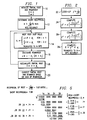
- the arithmetic unit of the present invention uses a novel method for performing the square root function. This method is shown in flow chart form in FIGURE 1. The method illustrated is specially suited to operate in an arithmetic unit which comprises a rectangular aspect ratio multiplier.
- the arithmetic unit of the present invention may comprise, for example, a rectangular multiplier having an aspect ratio of 19 x 69 bits. This multiplier may be used to perform the exact square root of 68 bit numbers by generating four 17-bit root digits.
- the desired full precision 68 bit partial root with non-negative remainder is viewed in the method of the present invention as composed of four signed 17-bit digits employing the large radix 2 17 .
- the method shown in FIGURE 1 is used to calculate the square root of an operand y.
- the operand y is normalized such that 1/4 ⁇ y ⁇ 1 and the value of its exponent is an even number.
- the square root function takes place by approximating the reciprocal of the root to a precision less than the precision of the operand to obtain a short reciprocal R.
- Root digit values, d i are serially determined and accumulated to generate a partial root D.
- Remainders are generated and stored in a register z.
- the method will be described with reference to an array multiplier having an aspect ratio of 19 x 69 bits. It should be understood, however, that the square root method of the present invention is applicable to a wide range of rectangular aspect ratio multipliers.
- the particular rectangular multiplier described herein is an embodiment chosen for the purposes of teaching the present invention, and should not be construed to limit the scope of the present invention as claimed.
- the method begins at step 10 wherein the remainder register z is loaded with the value of the operand y and the root register is set to zero. It should be understood that the method presupposes that the operand is a 68 bit number normalized to be less than one and the most significant bit of the 69 bit remainder register z, being the sole bit to the left of the binary radix point, is initially equal to 0.
- the short reciprocal R approximates the exact reciprocal to more than 18 bits of accuracy.
- the short reciprocal R is always greater than or equal to the true reciprocal 1/ y , where the true reciprocal is greater than one and less than or equal to two.
- the approximation step 12 uses a variation of the Newton-Raphson approximation technique which will be described more fully with reference to FIGURE 2.
- a first root digit value is calculated in step 14 by multiplying the operand now in the remainder register z by the short reciprocal R, generating a product 88 bits wide with at least one leading zero.
- the product of the short reciprocal and the operand then has a digit bias adjustment factor ⁇ 1 added to it.
- ⁇ 1 is equal to 3/8 of a unit relative to a unit in the last place to which the root digit value is truncated.
- the digit bias adjustment factors ⁇ 1 , ⁇ 2 , ⁇ 3 and ⁇ 4 are statically generated correction factors which are added to offset error resulting from the truncation of the products to form the signed 17-bit root digit values.
- the digit bias adjustment factor ⁇ i is added in to form the root digit value only if the root digit value being calculated is positive, observing that root digit values after the first may be negative.
- This limitation on adding ⁇ i is due to the fact that digit truncation error reduces magnitude, and thus acts to reduce root value for positive root digit values and acts to increase the root value for negative root digit values.
- Different digit bias adjustment factors are selectively added in the first root digit value computation as opposed to the second, third and fourth root digit value computations.
- the digit bias adjustment factors, ⁇ 2 , ⁇ 3 , ⁇ 4 are all equal to 1/2 a unit in the last place relative to truncation, and are added in the second, third and fourth root digit value computations before truncation only if the resulting root digit values will be positive.
- step 14 the sum of the product of the z register shifted to the right 1 place for root digit values after the first and the short reciprocal and the appropriate digit bias adjustment factor ⁇ i is then truncated to form a single signed 17-bit root digit value.
- the term digit is used herein with reference to the large radix 2 17 and without regards to normalization, corresponds to any positive or negative integer value having a magnitude of 2 17 -1 or less.
- four root digit values are required for the complete 68-bit root of a 68-bit operand.
- four passes through the multiplier will be required to generate the four root digit values.
- the ith signed 17-bit integer digit determined is taken to have a binary radix point 17(i-1) places to the left of its leftmost bit in specifying the corresponding root digit value.
- step 16 the remainder register z is updated for the calculation of the next root digit value.
- the new z register value is equal to the difference between the current remainder obtained from the z register and the product of the new root digit value and a quantity equal to the sum of twice the partial root and the new root digit value.
- step 14 the next root digit value is generated by taking the product of one-half the new remainder and the short reciprocal, conditionally adding the digit bias adjustment factor, and truncating.
- the root digit values are generated in series along with intermediate partial roots and exact remainders.
- the exact remainder of a full precision partial root is available for further processing.
- the partial root and remainder pair is not unique at this point due to the fact that the remainder may be either positive or negative, precise rounding can be performed at this point by suitable conditional rounding logic. According to the embodiment disclosed herein, a correction step is performed to obviate the need for conditional rounding logic.
- the square root process requires the generation of four root digit values to complete a full precision square root function.
- Each root digit requires a combined multiplication and addition step and a combined multiplication and subtraction step corresponding to step 14 and step 16, respectively.
- the multiplier also comprises an additional adder port.
- the additional adder port makes it possible to perform certain multiplication and addition steps in one pass through the rectangular multiplier. Accordingly, the operation shown in step 16 which compromises a 17 x 69 bit product and a difference, as well as the operations shown in step 14 which comprise certain 19 x 69 or certain 20 x 69 bit products with addition of a predetermined constant, can each be accomplished in a single pass through the rectangular multiplier.
- the partial root and remainder pair may be made unique by passing the partial root and the remainder through a correction sequence illustrated by step 20 in FIGURE 1. Because of steps taken in the estimation of the reciprocal in step 12, the correction sequence itself is fairly simple. In this embodiment the final remainder must be less than a positive quantity equal to the product of 2 -68 and twice the final partial root plus unity in the last place, and greater than a negative quantity equal to the product of -2 -68 and twice the final partial root minus unity in the last place. If the remainder is negative, the recalculation of the remainder comprises adding an appropriately shifted quantity equal to twice the final partial root minus one unit in the last place to the remainder. The final partial root is then decremented by one unit in the last place.
- FIGURE 2 A novel version of the Newton-Raphson estimation technique used to calculate the aforementioned short reciprocal value is shown in flow chart form in FIGURE 2.
- the method begins at step 22, where a look-up table is used to find a reciprocal seed value y' approximately equal to the reciprocal of the square root of the operand y. It should be understood that the method presupposes that the reciprocal seed value y' is normalized into typical floating point format such that y' is greater than or equal to one and less than two, and y' has a number of bits less than or equal to the smaller dimension of the rectangular aspect ratio multiplier. As discussed previously, the look-up table can only achieve a small number of bits due to the limits in the size of the table.
- y' is thus used as a seed value and the number of accurate bits in the approximation is increased through an iterative process.
- the seed value, y' is chosen to be of sufficient accuracy to produce an approximate reciprocal with absolute error less than 2 -22 before addition of the reciprocal bias adjustment factor.
- step 24 the first step of the iterative process is used to compute y".
- y is computed by computing a first result as the product of y and y'.
- the first result is truncated to 69 bits and multiplied by y'/2 and subtracted from 3/2 to form a second result.
- the second result is truncated to 69 bits and multiplied by y' to form a third result.
- the third result is truncated to 69 bits to obtain the value for y".
- step 26 the computation of an approximate reciprocal value, y′′′, is similarly calculated through an additional iteration of the Newton-Raphson approximation equation as shown, employing for y" the previously computed value of y" truncated to 17 bits for utilization in the shorter side of the multiplier.
- y' or y" could be used as the approximate reciprocal value if a different size multiplier were used in a different embodiment of the present invention requiring a smaller number of accurate bits in the short reciprocal R.
- Epsilon is a statically generated quantity dependent upon the radix of the root digit values. Epsilon is equal to the sum of two terms. The first term is equal to 2 -(N+k-1) where, as discussed previously N is equal to the number of bits of the radix of the root digit values and k is a predetermined number of guard bits. The second term is determined large enough to bias the result of the Newton-Raphson approximation to be larger than the true reciprocal.
- the second term must also be sufficiently small such that the determination of a root digit value in 14 will yield a remainder corresponding to less than one unit in the last place of the root digit value determined.
- Each iteration of the Newton-Raphson equation may require only three passes through a rectangular aspect ratio multiplier if the multiplier includes an additional adder port.
- the first pass forms the product y • y'.
- the second step forms the product and difference (3/2)-(y'/2)•(y ⁇ y').
- the third pass completes the iteration by forming y'• ⁇ (3/2)-(y'/2)•(y•y') ⁇ .
- the second term, (3/2)-(y'/2)• (y•y') may be calculated in a single pass through the rectangular multiplier.
- the results of these successive multiplies may each be truncated to the length of the long side of the rectangular multiplier as only an approximation of the reciprocal accurate to error less than one part in 2 23 is required.
- the method of performing the square root function of the present invention does not depend upon the particular method used to calculate the short reciprocal R.
- the above described variation of the Newton-Raphson process is merely one possible method of generating this value.
- a version of the Newton-Raphson approximation technique using a single iteration or more than two iterations to generate the approximate reciprocal value would be appropriate in a system using a multiplier which required a short reciprocal having less or more bits of accuracy, respectively, than the embodiment described herein.
- FIGURE 3 is a block diagram of one circuit embodiment capable of performing the method of performing the square root function of the present invention.
- a circuit indicated generally at 30, uses a system bus 32 for communication between a microprocessor [not shown] and an arithmetic coprocessor comprising circuit 30.
- System bus 32 may include, for example, the data lines, address lines and control lines from the microprocessor.
- Coupled to the system bus 32 are a D latch 34, a digit latch 36, a reciprocal latch 33 and an E latch 38.
- the D latch 34, the reciprocal latch 33 and the digit latch 36 receive operands from the microprocessor and store the operands to be used in an arithmetic operation and the E latch 38 serves to store the output of the operation.
- the reciprocal latch 33 receives nineteen bits from the system bus 32 and outputs the eighteen low order bits to a multiplexer 44. The leading bit is output to a shifter 52 which is coupled between the feedback register 54 and the input to the adder 48.
- the digit latch 36 receives seventeen bits from the system bus 32 and outputs the seventeen bits to the multiplexer 44 and to a multiplexer 35. The output of multiplexer 35 is coupled through three separate data paths to an adder 37.
- the D latch 34 receives sixty-nine bits from the system bus 32 and outputs the sixty-nine bits to the adder 37. The output of the adder 37 is input into a multiplexer 40.
- Actions relevant to the signs of the quantities involved are assumed to be handled either by the background control or by taking all bits to be signed bits of a redundant binary implementation.
- the multiplexer 35 is operable to input a digit stored in digit latch 36 into the adder 37 such that the digit may be appropriately aligned into three separate groups of bit positions.
- the remaining input to multiplexer 40 is coupled to the output of the feedback register 54 and the output of the multiplexer 40 is input into the long side of the multiplier array 42.
- Multiplier array 42 comprises a tree of adder arrays.
- the multiplicand is loaded into the D latch 34, and the multiplier is loaded into the digit latch 36 or reciprocal latch.
- the mutiplier comprises the "short" operand comprising 18 bits.
- the multiplicand comprises the "long” operand comprising 69 bits.
- the multiplicand passes through first multiplexer 40 and is input into the multiplier array 42.
- the 18 bits of the multiplier are input from the second multiplexer 44 into the short side of the multiplier array 42.
- the output of the multiplier array is 87 bits wide and forms one input into a first adder 46.
- the second port of first adder 46 serves as the additional adder port of the multiplier which was described previously.
- the second port of first adder 46 is coupled to the output of a second adder 48 which has at its inputs a constant port 50 and the output of the feedback register 54.
- Sixty-nine bits of the output of the feedback register 54 are also coupled to a second input port of the first multiplexer 40, thereby permitting an 18 x 69 bit product of feedback register 54 with second multiplexer 44 to be conditionally summed again with the contents of feedback register 54 which is passed through shifter 52 yielding a 19 x 69 bit total product at the output of first adder 46.
- the short reciprocal When the square root of the operand is equal to or near one half, the short reciprocal will be equal to or slightly greater than two. This causes the 19 bit short reciprocal to overflow in our normalization leaving a O in the most significant bit position. This condition is detected by examining the most significant bit, and causes shifter 52 to shift left by one which has the effect of adding in twice the contents of the feedback register 54 to properly handle these particular 20 x 69 bit multiplies.
- the adder 46 is its ability to detect overflow and saturate the resulting sum. During the computation of the root digit values, the product of a short reciprocal and a remainder could create overflow indicating a digit with magnitude greater than 2 17 -1. Therefore, the saturation feature of adder 46 is operable to provide a maximum sum corresponding to a 1 on all 86 output bits to the right of the implied binary radix point of adder 46, corresponding to a digit magnitude of 2 17 -1.
- the output of the first adder 46 is coupled to the input of a first shifter 55.
- First shifter 55 operates to shift the output of first adder 46 to the right or left by one place. This shifting is used to keep the maximum number of significant data bits flowing in the data path and for alignment to multiply by one half the remainder as was discussed with reference to step 14 of FIGURE 1.
- first shifter 55 is input into a result register 56.
- the output of the result register 56 is fed into two separate locations.
- the output is first fed into a second shifter 58 which is coupled between the result register 56 and the input to the feedback register 54, from which it may subsequently be returned to multiplier array 42 or adders 48 or 46 for other computations.
- Shifter 58 is used to shift values in the data path to the left by 17 bits.
- Shifter 58 is used to once again maintain as many significant data bits as possible in the data path by shifting out bits whose value is known. Because of the features of the method of the present invention, the initial 17 bits of the result of the subtraction step generating the succeeding remainder are always 0. This is due to the fact that the initial bits of the operands of this subtraction step always cancel. These 0 bits are therefore shifted out to the left to allow for 17 additional significant data bits to remain in the data path.
- the output of the result register 56 is input into the E latch 38 which as described previously, is coupled to the system bus 32.
- the system bus 32 is also coupled to an accumulator circuit, indicated generally at 70.
- Accumulator 70 comprises an adder 72 which has one of its ports coupled to the system bus 32. The remaining port of adder 72 is coupled to a shifter 74.
- the output of adder 72 is input into a root register 76 which is also coupled to the input of shifter 74.
- the output of the root register 76 is also coupled to the system bus 32. This connection supplies a data path by which the partial root may return to the D latch 34 for the calculation of the succeeding remainder as was discussed with reference to step 16 shown in FIGURE 1.
- the basic operation used to perform the novel square root method of the present invention is the multiplication operation. It is important to distinguish between different types of multiplication operations, however.
- Prior art methods of performing the square root function calculated a full length, full precision approximation of the reciprocal of the root and then performed a full precision, "long-by-long" multiplication. An additional full precision multiplication was then used to correct the result.
- the square root method of the present invention does not require any full precision multiplications.
- the multiplication operations necessary for the present method are much simpler and quicker "short-by-long" multiplications.
- the method of performing the exact square root function of the present invention is perhaps best understood when examined in conjunction with the conventional long hand square root method.
- the two methods are most easily compared if examples are used which calculate the square roots in the more familiar base 10.
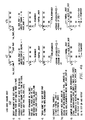
- FIGURE 4a illustrates in tabular form the steps required to perform the conventional long hand square root method.
- FIGURE 4b illustrates the long hand method used to calculate the square root of two
- FIGURE 4c illustrates the long hand method used to calculate the square root of 20. Both examples are calculated in base 10.
- step 1 entails grouping the arguments into digit pairs. It is important to note at this point that the decimal point must not be within a pair of digits. It is important to realize that the exponent of the argument must be respected. This can be seen in the following example in that the square root of two does not contain the same significant digits as the square root of 20.
- the first digit of the root is generated by recalling the largest perfect square less than or equal to the first digit pair and using the root of this perfect square as the first digit. In the example shown, the largest perfect square less than or equal to two is one, and therefore the first root digit of the square root of two is one. The largest perfect square which is less than 20 is 16, and therefore, the first digit of the root of 20 is four.
- step 3 the remainder is computed as the difference between the first digit pair and the first root digit squared.
- step 4 the next digit pair is brought down to form the new remainder. It is a feature of the long hand square root method that both the remainder and new remainder are defined by these limited number of digits with subsequent digits of the original operand brought into the computation at the rate of one new digit pair per cycle.
- the new remainder is 100, and in the square root of 20 example, the new remainder is 400 as shown.
- step 5a a trial divisor is computed equal to two times the base times the partial root.
- the first trial divisor is equal to 20.
- the first trial divisor is equal to 80.
- step 5b the next root digit is computed by dividing the new non zero remainder by the trial divisor, rounding up the quotient and subtracting one. If the new remainder is zero, the next root digit is set to zero. In both the square root of two and square root of 20 examples, the next root digit is computed to be four yielding partial roots of 1.4 for 2 and 4.4 for 20 as shown.
- step 6 the next remainder is computed. The next remainder is equal to the product of the next root digit, and the sum of the trial divisor and the next root digit. In the square root of two example, the next remainder is computed to be equal to four. In the square root of 20 example, the next remainder is computed to be 64. At this point the next remainder may be negative. It is a feature of the long hand square root that the computation of step 5b does not always identify the appropriate next digit. In this case the current estimate of the next digit is decremented by one and step 6 repeated.
- the method then returns to step 4 where the next digit pair is brought down to form the new remainder.
- the long hand method can then proceed indefinitely to generate as many digits of the square root as are desired. It can be seen from the examples illustrated in FIGURE 4a that the conventional long hand square root method requires a large number of complex arithmetic operations to generate each digit of the root. The iterative steps required for the generation of each root digit occupy an arithmetic processor's time with at least one multiplication operation, one division operation and a number of additional shifting and adding operations.
- FIGURE 4b the conventional long hand square root method is used to calculate the square root of two.
- the summation of twice the previous digits plus the last digit to be calculated (underlined) is shown.
- This term with the yet to be determined last digit (underlined) taken as zero constitutes the trial divisor which was discussed with reference to step 5 in FIGURE 4a.
- FIGURE 4c illustrates the conventional long hand square root method used to calculate the square root of 20 to a partial root with nine digits of accuracy with positive remainder.
- FIGURE 5 shows the computation of the square root of .02 using the method illustrated by the flowchart shown in FIGURE 1.
- the example shown in FIGURE 5 uses large radix digits of base 100.
- the large radix digits of the operand are themselves grouped into digit pairs, each group then having four decimal places.
- the reciprocal of the square root of two is approximated to be equal to 7.08. This corresponds to the calculation of the short reciprocal discussed previously.
- the initial digit of the root is calculated by multiplying 7.08 times the operand 2 yielding .1416, then the small digit bias adjustment factor is added and truncation yields .14 as the first root digit value.
- This first root digit value is squared and subtracted from the initial operand to yield the new remainder .0004.
- the successive remainders in FIGURE 5 are shown with a radix point corresponding to two more leading zeroes deleted each cycle to illustrate how remainders appear when shifted left in the z register to maintain more digits in the data path as discussed with reference to shifter 58 in FIGURE 3.
- One-half this remainder is then multiplied by the short reciprocal, the digit bias adjustment factor is added with truncation then yielding the next root digit value equal to .0014.
- This root digit value is then added to twice the previously partial root to yield the sum .2814.
- the root digit value, .0014 is then multiplied times the sum, .2814, to yield .0003 9396. This product is then subtracted from the previous remainder to yield the next remainder equal to .00000604. This process continues for the generation of the last two root digit values equal to .000021 and .00000036, respectively. The process concludes with the partial root .14142136 and corresponding negative remainder -.0000 0000 1064 2496.
- the negative remainder is made positive by a step not illustrated in FIGURE 5 by adding a quantity given by 10 -8 times the sum of twice the partial root minus unity in the last place, yielding the final remainder .0000 0000 1764 1775 corresponding to the decremented final partial root .14142135.
- FIGURE 5 illustrates that through using a single short-by-long multiplication step each, the root digit values are serially generated and the corresponding new exact remainders are determined.
- the method requires the accumulation of twice the previous partial root plus the new root digit value as a multiplicand.
- the short reciprocal is calculated such that the remainder following the calculation of each root digit value corresponds in magnitude to less than one unit in the last place of the preceeding root digit value.
- the approximation of the reciprocal is generated as described previously and stored in the reciprocal latch 33.
- the operand is loaded into the feedback register 54 by passing it unchanged from the system bus 32 through circuit 30.
- the feedback register 54 thus acts as the z register referred to with respect to FIGURE 1.
- the operand is selected by multiplexer 40 from the feedback register 54 and is multiplied by the short reciprocal.
- the 18 low order bits of the short reciprocal are loaded through a multiplexer 44 into the multiplier array 42 with the product input to one port of adder 46.
- the operand is also fed to shifter 52 to allow multiplication by the leading bit of the short reciprocal generating a result on one input port to adder 48.
- the other input port of adder 48 receives the digit bias adjustment factor ⁇ 1 , from constant port 50.
- the sum output from adder 48 is added to the product from multiplier 42 in adder 46 outputing the result to shifter 55.
- the seventeen most significant bits of the result constitutes the first root digit value.
- the first root digit value is then loaded into the digit latch 36 and the D-LATCH, 34.
- the root digit value is also loaded through adder 72 into root register 76.
- the first remainder is calculated by first squaring the first root digit value. This is accomplished by loading the first root digit value into the long side of the multiply array 42. This load is accomplished by passing the first root digit value from the D-LATCH 34 through adder 37 and multiplexer 40. The multiplexer 35 outputs a zero into the adder 37 so that the first root digit value is unchanged as it passes through adder 37. The first root digit value is also loaded from the digit latch 36 through multiplexer 44 into the short side of the multiplier array 42. The multiplier array 42 then accomplishes the squaring of the first root digit value. The operand is passed from feedback register 54 through second adder 48 into first adder 46 where the square of the first root digit value is subtracted.
- first adder 46 is shifted right one place in shifter 55 and is passed to the result register 56 and constitutes one-half the new remainder which is then shifted to the left 17 bits in third shifter 58.
- the first seventeen bits of the remainder are all zero resulting from the fact that the initial bits of the operands of the subtraction operation cancel.
- the shifted remainder is then loaded into feedback register 54 to enable the calculation of the next root digit value.
- the actual quantity loaded in register 54 is equal to one-half the remainder due to its alignment through shifter 55 in preparation for the next root digit value computation in step 14.
- the result from root register 76 is now passed to the D-LATCH 34 aligned by one bit to provide a quantity equal to twice the partial root to be available to adder 37 for computation of the new remainder on the subsequent iteration of step 16.
- Each succeeding root digit value is calculated by multiplying the short reciprocal which is loaded into the multiplier array 42 through multiplexer 44 with the short reciprocal leading bit input to shifter 52 by one-half the remainder which is present in the feedback register 54 and is loaded into shifter 52 and into the long side of multiplier array 42 through multiplexer 40.
- the digit bias adjustment factors ⁇ 2 , ⁇ 3 and ⁇ 4 are input from constant port 50 and conditionally added to the leading part of the product in adder 48 which result is then added to the output of multiplier 42 in adder 46.
- ⁇ 2 is equal to one-half unit in the last place to which the result will be truncated, and is added to alleviate error introduced as a result of the truncation to seventeen bits.
- each digit is generated, it is loaded into the digit latch 36 and into accumulator 70, where it is added to the partial root in adder 72 after the partial root has been shifted to the left seventeen places in shifter 74.
- the partial root is then loaded into root register 76 but not passed to the D-LATCH 34 at this time as the next remainder computation must use the previous partial root value.
- the next remainder can thus be calculated by adding the new digit value stored in digit latch 36 to a quantity equal to twice the preceeding partial root available to adder 37 from the D-latch 34.
- the multiplexer 35 takes care of the alignment of the digits depending on whether it is the second, third or fourth digit calculated.
- Adder 37 is necessary to accommodate the borrow from the partial root which may result if the digit loaded in digit latch 36 is a negative number.
- the quantity (2D + d i ) output from adder 37 is input into the long side of multiplier array 42, and the digit d i is passed through multiplier 44 into the short side of multiplier array 42.
- the value of one half the remainder present in feedback register 54 is doubled in shifter 52 yielding the remainder as input into adder 46. Consequently, the product output from the multiplier array 42 can then be subtracted from the remainder in adder 46. In this manner, the new remainder is calculated in a single calculation step because of the inclusion in circuit 30 of an additional adder port embodied in adder 46.
- the value of the digit bias adjustment factors, ⁇ 3 and ⁇ 4 which are added if the current root digit is positive, are also equal to one-half unit in the last place to which the result will be truncated.
- the circuit 30 then performs a correction sequence based on the value of the final remainder. If the final remainder is negative, the correction of the remainder indicated in step 20 may be accomplished by passing the final partial root through the adder 37 and multiplier 42 unchanged to adder 46 to be added to the value of one half the remainder obtained through shifter 52 with the subtraction of the unit in the appropriate last position from constant port 50 performed in adder 48 prior to the addition in adder 46. The resulting value equal to one half the final remainder is shifted left one place in shifter 55 to provide the final remainder for output to result register 56.
- the final partial root after the conditional borrow resides in root register 76 as accumulator circuit 70 comprises the necessary circuitry to conditionally decrement the partial root present in root register 76.
- the present invention provides a method of performing the exact square root which comprises approximating the reciprocal of the root and serially generating large radix root digit values and exact remainders.
- a reciprocal bias adjustment factor is added to the approximation of the reciprocal and digit bias adjustment factors are added in each positive root digit value computation prior to truncation to insure that any error within a particular root digit value will be limited to less than one unit of error in the last place of the truncated digit. This is to ensure that the error in the digit can be compensated for in the calculation of the remaining root digit values.
- the particular circuit embodiment described herein uses a rectangular multiplier array having an aspect ratio of 18 bits by 69 bits including an additional adder port.
- the rectangular multiplier of this circuit is particularly suited to the square root operation of the present invention as the short side of the multiplier array comprises substantially the same number of bits as a single root digit value.
Landscapes
- Engineering & Computer Science (AREA)
- Physics & Mathematics (AREA)
- General Physics & Mathematics (AREA)
- Theoretical Computer Science (AREA)
- Pure & Applied Mathematics (AREA)
- Mathematical Analysis (AREA)
- Computational Mathematics (AREA)
- Computing Systems (AREA)
- Mathematical Optimization (AREA)
- General Engineering & Computer Science (AREA)
- Complex Calculations (AREA)
- Analysing Materials By The Use Of Radiation (AREA)
- Executing Machine-Instructions (AREA)
Abstract
Description
Claims (12)
- A circuit for calculating an exact square root of an operand, comprising:circuitry for obtaining a short reciprocal of the square root of the operand (12 in Figure 1) by adding a reciprocal bias adjustment factor to an approximate reciprocal to yield a sum and truncating said sum to yield said short reciprocal, said reciprocal bias adjustment factor chosen to offset accumulated error in the approximate reciprocal and bias said short reciprocal to produce root digit values which, when accumulated to form a partial root, are always at most one unit in the last place greater than or exactly equal to an exact value of the square root truncated to a predetermined number of bits;circuitry for calculating a first root digit value by (a) multiplying the short reciprocal by said operand, (b) adding a first digit bias adjustment factor, and (c) truncating to a predetermined number of bits, said first digit bias adjustment factor operable to offset error introduced by the truncation (14 in Figure 1);circuitry for calculating a first remainder as the difference between said operand and the square of said first root digit value (16 in Figure 1);circuitry for iteratively calculating successive root digit values, each successive root digit value being calculated by (a) forming a first product by multiplying said short reciprocal by one half of (i) in the case of a first successive root digit value, said first remainder, or (ii) in the case of second and subsequent successive root digit values, a previous remainder, (b) if said first product is positive, adding a second digit bias adjustment factor, and (c) truncating said first product to a predetermined number of bits to generate said successive root digit value, for positive first products said digit bias adjustment factor being operable to offset error introduced by said truncation (14 in Figure 1);circuitry for iteratively generating, for each successive root digit value, a second product of (a) said successive root digit value and (b) a sum of said successive root digit value and twice (i) in the case of said first successive root digit value, said first root digit value, or (ii) in the case of second and subsequent successive root digit values, a partial root (16 in Figure 1);circuitry for iteratively calculating, for each successive root digit value, a successive remainder as the difference between (a) in the case of said first successive root digit value, said first remainder, or (b) in the case of second and subsequent successive root digit values, a previous remainder, and (c) said second product, said first and successive root digit values and said respective first and successive remainders calculated such that each remainder has a magnitude corresponding to less than one unit in the last place of said corresponding root digit value (16 in Figure 1); andcircuitry for calculating said partial root, said partial root comprising a sum of all appropriately shifted root digit values (18 in Figure 1).
- The circuit of Claim 1 wherein said first root digit value gives rise to a negative first remainder when said first root digit value is greater than an exact value of the square root truncated to a predetermined number of bits, said first negative remainder causing said second root digit value to be negative, thereby causing said partial root to have a value less than the value of said first root digit value.
- The circuit of Claim 1 wherein said circuitry for calculating a partial root comprises circuitry for calculating a sum of the appropriately shifted root digit values, said sum forming a partial root of a partial root and remainder pair, said pair composing the exact square root of the operand.
- The circuit of Claim 1 wherein said circuitry for obtaining said short reciprocal comprises:look-up table circuitry for storing a plurality of reciprocal seed values (22 in Figure 2);retrieval circuitry coupled to said look-up table circuitry for retrieving a particular reciprocal seed value approximately equal to the reciprocal of the square root of the operand (22 in Figure 2);circuitry for calculating a first reciprocal approximation equal to the product of said particular reciprocal seed value and the difference of three-halves and a second term, said second term being the product of said particular seed value and a third term, said third term being the product of one-half of said operand and said particular reciprocal seed value (24 in Figure 2); andcircuitry for calculating a second reciprocal approximation equal to the product of said first reciprocal approximation and the difference of three halves and a fourth term, said fourth term being the product of said first reciprocal approximation and a fifth term, said fifth term being the product of one-half of the operand and said first reciprocal approximation (26 in Figure 2).
- The circuit of Claim 4 wherein said circuitry for obtaining said short reciprocal further comprises:
circuitry for calculating said short reciprocal equal to the truncated sum of a prior reciprocal approximation and a reciprocal bias adjustment factor (28 in Figure 2) chosen to offset accumulated error in said prior reciprocal approximation and bias said short reciprocal to produce root digit values which, when accumulated to form a partial root, yield a partial root at most one unit in the last place greater than or exactly equal to the exact value of the square root truncated to a predetermined number of bits. - The circuit of Claim 5 wherein said prior reciprocal approximation is equal to said second reciprocal approximation.
- The circuit of Claim 5 wherein said reciprocal bias adjustment factor is equal to the sum of a first and a second term, said first term equal to 2-k in the Nth place where N is equal to the number of bits of the radix of the root digit values and k is a predetermined number of guard bits, said second term being large enough to bias said short reciprocal such that said short reciprocal is larger than an exact reciprocal of the square root of the operand and said second term being small enough such that said first and second remainders correspond to less than one unit in the last place of said first and second root digit values, respectively.
- A method for calculating an exact square root of an operand, comprising the steps of:calculating a short reciprocal (12 in Figure 1) by adding a reciprocal bias adjustment factor to an approximate reciprocal to yield a sum and truncating said sum to yield said short reciprocal, said reciprocal bias adjustment factor chosen to offset accumulated error in the approximate reciprocal and bias said short reciprocal to produce root digit values which, when accumulated to form a partial root, are always at most one unit in the last place greater than or exactly equal to an exact value of the square root truncated to a predetermined number of bits;inputting the short reciprocal of the operand (12 in Figure 1) into a first input of a multiplier circuit;inputting a remainder value initially equal to the operand (10 in Figure 1) into a second input of the multiplier circuit;iteratively calculating a first and a desired number of successive root digit values (14 in Figure 1) from a first and successive root digit products each obtained by multiplying the short reciprocal of the operand by a first term equal to one half of the remainder value, for the first root digit product, the first term being equal to the operand;adding a first digit bias adjustment factor to the first root digit product, and selectively adding a second root digit value to each of the successive root digit products if such root digit product is positive (14 in Figure 1);truncating the product to a predetermined number of bits to generate the root digit value, for positive root digit products, the digit bias adjustment factor operable to offset error introduced by the truncation;iteratively calculating a partial root as the sum of all appropriately shifted root digit values (18 in Figure 1); anditeratively calculating, for each successive root digit value, a successive remainder (16 in Figure 1) as the difference between (a) the remainder value and (b) a product of (i) the root digit value and (ii) a sum of the root digit value and a second term equal to twice the previous partial root, the second term initially equal to zero, said successive root digit values and said successive remainders calculated such that each remainder has a magnitude corresponding to less than one unit in the last place of a preceding root digit value (14 in Figure 1).
- The method of Claim 8 wherein the root digit values give rise to a negative remainder when the root digit values are greater than the exact value, the negative remainder causing a subsequent root digit value to be negative, thereby causing a product of the subsequent root digit and a term comprising the sum of the subsequent root digit and twice the previous partial root operable to reduce the magnitude of the negative remainder.
- The method of Claim 8 wherein the step of calculating a short reciprocal of the operand comprises the steps of:retrieving a reciprocal seed value from a table containing a plurality of values;calculating a first reciprocal approximation equal to the product of the particular reciprocal seed value and the difference of three-halves and a second term, the second term being the product of the particular reciprocal seed value and a third term, the third term being the product of one-half of the operand and the particular reciprocal seed value; andcalculating a second reciprocal approximation equal to the product of the first reciprocal approximation and the difference of three-halves and a fourth term, the fourth term being the product of the first reciprocal approximation and a fifth term, the fifth term being the product of one-half of the operand and the first reciprocal approximation.
- The method of Claim 10 wherein the step of calculating a short reciprocal of the operand further comprises the step of:
calculating the short reciprocal equal to the truncated sum of a prior reciprocal approximation and a reciprocal bias adjustment factor chosen to offset accumulated error in the prior reciprocal approximation and bias the short reciprocal to produce root digit values which, when accumulated to form a partial root, yield a partial root at most one unit in the last place greater than or exactly equal to the exact value of the square root truncated to a predetermined number of bits. - The method of Claim 11 wherein the reciprocal bias adjustment factor is equal to the sum of a first and a second term, the first term equal to 2-k in the Nth place where N is equal to the number of bits of the radix of the root digit values and k is a predetermined number of guard bits, the second term being large enough to bias the short reciprocal such that the short reciprocal is larger than an exact reciprocal of the square root of the operand and the second term being small enough to yield remainders corresponding to less than one unit in the last place of a preceding root digit value.
Applications Claiming Priority (2)
| Application Number | Priority Date | Filing Date | Title |
|---|---|---|---|
| US07/402,822 US5060182A (en) | 1989-09-05 | 1989-09-05 | Method and apparatus for performing the square root function using a rectangular aspect ratio multiplier |
| US402822 | 1989-09-05 |
Publications (3)
| Publication Number | Publication Date |
|---|---|
| EP0416309A2 EP0416309A2 (en) | 1991-03-13 |
| EP0416309A3 EP0416309A3 (en) | 1992-05-13 |
| EP0416309B1 true EP0416309B1 (en) | 1999-01-13 |
Family
ID=23593421
Family Applications (1)
| Application Number | Title | Priority Date | Filing Date |
|---|---|---|---|
| EP90115266A Expired - Lifetime EP0416309B1 (en) | 1989-09-05 | 1990-08-09 | Method and apparatus for performing the square root function using a rectangular aspect ratio multiplier |
Country Status (5)
| Country | Link |
|---|---|
| US (1) | US5060182A (en) |
| EP (1) | EP0416309B1 (en) |
| JP (1) | JPH03171324A (en) |
| AT (1) | ATE175790T1 (en) |
| DE (1) | DE69032890T2 (en) |
Families Citing this family (19)
| Publication number | Priority date | Publication date | Assignee | Title |
|---|---|---|---|---|
| EP0394499B1 (en) * | 1988-11-04 | 1997-10-08 | Hitachi, Ltd. | Apparatus for multiplication, division and extraction of square root |
| US5278782A (en) * | 1991-06-03 | 1994-01-11 | Matsushita Electric Industrial Co., Ltd. | Square root operation device |
| US5268857A (en) * | 1992-01-08 | 1993-12-07 | Ncr Corporation | Device and method for approximating the square root of a number |
| US6260054B1 (en) | 1998-10-29 | 2001-07-10 | Neomagic Corp. | Reciprocal generator using piece-wise-linear segments of varying width with floating-point format |
| US6963895B1 (en) * | 2000-05-01 | 2005-11-08 | Raza Microelectronics, Inc. | Floating point pipeline method and circuit for fast inverse square root calculations |
| TWI235948B (en) * | 2004-02-11 | 2005-07-11 | Via Tech Inc | Accumulatively adding device and method |
| US20070083586A1 (en) * | 2005-10-12 | 2007-04-12 | Jianjun Luo | System and method for optimized reciprocal operations |
| US9612800B2 (en) * | 2014-08-05 | 2017-04-04 | Imagination Technologies Limited | Implementing a square root operation in a computer system |
| US9811503B1 (en) | 2015-01-28 | 2017-11-07 | Altera Corporation | Methods for implementing arithmetic functions with user-defined input and output formats |
| US11080229B2 (en) | 2016-02-13 | 2021-08-03 | HangZhou HaiCun Information Technology Co., Ltd. | Processor for calculating mathematical functions in parallel |
| WO2017137015A2 (en) | 2016-02-13 | 2017-08-17 | 成都海存艾匹科技有限公司 | Processor containing three-dimensional memory array |
| US11966715B2 (en) | 2016-02-13 | 2024-04-23 | HangZhou HaiCun Information Technology Co., Ltd. | Three-dimensional processor for parallel computing |
| US10848158B2 (en) | 2016-02-13 | 2020-11-24 | HangZhou HaiCun Information Technology Co., Ltd. | Configurable processor |
| US11527523B2 (en) | 2018-12-10 | 2022-12-13 | HangZhou HaiCun Information Technology Co., Ltd. | Discrete three-dimensional processor |
| US10445067B2 (en) | 2016-05-06 | 2019-10-15 | HangZhou HaiCun Information Technology Co., Ltd. | Configurable processor with in-package look-up table |
| CN107357551B (en) | 2016-05-10 | 2021-01-26 | 成都海存艾匹科技有限公司 | Processor for implementing at least two types of functions |
| US11734550B2 (en) | 2018-12-10 | 2023-08-22 | HangZhou HaiCun Information Technology Co., Ltd. | Discrete three-dimensional processor |
| US11296068B2 (en) | 2018-12-10 | 2022-04-05 | HangZhou HaiCun Information Technology Co., Ltd. | Discrete three-dimensional processor |
| KR102731350B1 (en) | 2022-01-09 | 2024-11-15 | 쥐에스아이 테크놀로지 인코포레이티드 | Square root calculation in the associative processing unit |
Family Cites Families (6)
| Publication number | Priority date | Publication date | Assignee | Title |
|---|---|---|---|---|
| US4338675A (en) * | 1980-02-13 | 1982-07-06 | Intel Corporation | Numeric data processor |
| US4594680A (en) * | 1983-05-04 | 1986-06-10 | Sperry Corporation | Apparatus for performing quadratic convergence division in a large data processing system |
| US4734878A (en) * | 1985-10-31 | 1988-03-29 | General Electric Company | Circuit for performing square root functions |
| US4757467A (en) * | 1986-05-15 | 1988-07-12 | Rca Licensing Corporation | Apparatus for estimating the square root of digital samples |
| US4878190A (en) * | 1988-01-29 | 1989-10-31 | Texas Instruments Incorporated | Floating point/integer processor with divide and square root functions |
| US4901267A (en) * | 1988-03-14 | 1990-02-13 | Weitek Corporation | Floating point circuit with configurable number of multiplier cycles and variable divide cycle ratio |
-
1989
- 1989-09-05 US US07/402,822 patent/US5060182A/en not_active Expired - Lifetime
-
1990
- 1990-08-09 EP EP90115266A patent/EP0416309B1/en not_active Expired - Lifetime
- 1990-08-09 AT AT90115266T patent/ATE175790T1/en active
- 1990-08-09 DE DE69032890T patent/DE69032890T2/en not_active Expired - Fee Related
- 1990-09-05 JP JP2233437A patent/JPH03171324A/en active Pending
Also Published As
| Publication number | Publication date |
|---|---|
| ATE175790T1 (en) | 1999-01-15 |
| EP0416309A2 (en) | 1991-03-13 |
| JPH03171324A (en) | 1991-07-24 |
| DE69032890D1 (en) | 1999-02-25 |
| EP0416309A3 (en) | 1992-05-13 |
| US5060182A (en) | 1991-10-22 |
| DE69032890T2 (en) | 1999-08-05 |
Similar Documents
| Publication | Publication Date | Title |
|---|---|---|
| US5046038A (en) | Method and apparatus for performing division using a rectangular aspect ratio multiplier | |
| US5307303A (en) | Method and apparatus for performing division using a rectangular aspect ratio multiplier | |
| US5060182A (en) | Method and apparatus for performing the square root function using a rectangular aspect ratio multiplier | |
| EP0421092B1 (en) | Method and apparatus for performing mathematical functions using polynomial approximation and a rectangular aspect ratio multiplier | |
| JP2598507B2 (en) | Division or square root calculator | |
| US6163791A (en) | High accuracy estimates of elementary functions | |
| US6049865A (en) | Method and apparatus for implementing floating point projection instructions | |
| US6230179B1 (en) | Finite field multiplier with intrinsic modular reduction | |
| Pineiro et al. | Algorithm and architecture for logarithm, exponential, and powering computation | |
| US5245564A (en) | Apparatus for multiplying operands | |
| US8838664B2 (en) | Methods and apparatus for compressing partial products during a fused multiply-and-accumulate (FMAC) operation on operands having a packed-single-precision format | |
| JPH02196328A (en) | Floating point computing apparatus | |
| JPH1078863A (en) | Method for executing microprocessor integer division operation using floating point type hardware and device therefor | |
| US5184318A (en) | Rectangular array signed digit multiplier | |
| US5023827A (en) | Radix-16 divider using overlapped quotient bit selection and concurrent quotient rounding and correction | |
| US5132925A (en) | Radix-16 divider using overlapped quotient bit selection and concurrent quotient rounding and correction | |
| US5144576A (en) | Signed digit multiplier | |
| US5159566A (en) | Method and apparatus for performing the square root function using a rectangular aspect ratio multiplier | |
| US5790444A (en) | Fast alignment unit for multiply-add floating point unit | |
| US6847986B2 (en) | Divider | |
| US7921149B2 (en) | Division and square root arithmetic unit | |
| JPH05204611A (en) | Method and device for executing pre-scale type division | |
| CN109298848A (en) | Circuit for double-mode floating point division square root | |
| US6952710B2 (en) | Apparatus, methods and computer program products for performing high speed division calculations | |
| US7080112B2 (en) | Method and apparatus for computing an approximation to the reciprocal of a floating point number in IEEE format |
Legal Events
| Date | Code | Title | Description |
|---|---|---|---|
| PUAI | Public reference made under article 153(3) epc to a published international application that has entered the european phase |
Free format text: ORIGINAL CODE: 0009012 |
|
| AK | Designated contracting states |
Kind code of ref document: A2 Designated state(s): AT BE CH DE DK ES FR GB GR IT LI LU NL SE |
|
| PUAL | Search report despatched |
Free format text: ORIGINAL CODE: 0009013 |
|
| AK | Designated contracting states |
Kind code of ref document: A3 Designated state(s): AT BE CH DE DK ES FR GB GR IT LI LU NL SE |
|
| 17P | Request for examination filed |
Effective date: 19921112 |
|
| 17Q | First examination report despatched |
Effective date: 19951213 |
|
| GRAG | Despatch of communication of intention to grant |
Free format text: ORIGINAL CODE: EPIDOS AGRA |
|
| GRAG | Despatch of communication of intention to grant |
Free format text: ORIGINAL CODE: EPIDOS AGRA |
|
| GRAH | Despatch of communication of intention to grant a patent |
Free format text: ORIGINAL CODE: EPIDOS IGRA |
|
| GRAH | Despatch of communication of intention to grant a patent |
Free format text: ORIGINAL CODE: EPIDOS IGRA |
|
| GRAA | (expected) grant |
Free format text: ORIGINAL CODE: 0009210 |
|
| AK | Designated contracting states |
Kind code of ref document: B1 Designated state(s): AT BE CH DE DK ES FR GB GR IT LI LU NL SE |
|
| PG25 | Lapsed in a contracting state [announced via postgrant information from national office to epo] |
Ref country code: IT Free format text: LAPSE BECAUSE OF FAILURE TO SUBMIT A TRANSLATION OF THE DESCRIPTION OR TO PAY THE FEE WITHIN THE PRE;WARNING: LAPSES OF ITALIAN PATENTS WITH EFFECTIVE DATE BEFORE 2007 MAY HAVE OCCURRED AT ANY TIME BEFORE 2007. THE CORRECT EFFECTIVE DATE MAY BE DIFFERENT FROM THE ONE RECORDED.SCRIBED TIME-LIMIT Effective date: 19990113 Ref country code: LI Free format text: LAPSE BECAUSE OF FAILURE TO SUBMIT A TRANSLATION OF THE DESCRIPTION OR TO PAY THE FEE WITHIN THE PRESCRIBED TIME-LIMIT Effective date: 19990113 Ref country code: BE Free format text: LAPSE BECAUSE OF FAILURE TO SUBMIT A TRANSLATION OF THE DESCRIPTION OR TO PAY THE FEE WITHIN THE PRESCRIBED TIME-LIMIT Effective date: 19990113 Ref country code: SE Free format text: THE PATENT HAS BEEN ANNULLED BY A DECISION OF A NATIONAL AUTHORITY Effective date: 19990113 Ref country code: NL Free format text: LAPSE BECAUSE OF FAILURE TO SUBMIT A TRANSLATION OF THE DESCRIPTION OR TO PAY THE FEE WITHIN THE PRESCRIBED TIME-LIMIT Effective date: 19990113 Ref country code: CH Free format text: LAPSE BECAUSE OF FAILURE TO SUBMIT A TRANSLATION OF THE DESCRIPTION OR TO PAY THE FEE WITHIN THE PRESCRIBED TIME-LIMIT Effective date: 19990113 Ref country code: FR Free format text: LAPSE BECAUSE OF FAILURE TO SUBMIT A TRANSLATION OF THE DESCRIPTION OR TO PAY THE FEE WITHIN THE PRESCRIBED TIME-LIMIT Effective date: 19990113 Ref country code: ES Free format text: THE PATENT HAS BEEN ANNULLED BY A DECISION OF A NATIONAL AUTHORITY Effective date: 19990113 Ref country code: AT Free format text: LAPSE BECAUSE OF FAILURE TO SUBMIT A TRANSLATION OF THE DESCRIPTION OR TO PAY THE FEE WITHIN THE PRESCRIBED TIME-LIMIT Effective date: 19990113 Ref country code: GR Free format text: LAPSE BECAUSE OF NON-PAYMENT OF DUE FEES Effective date: 19990113 |
|
| REF | Corresponds to: |
Ref document number: 175790 Country of ref document: AT Date of ref document: 19990115 Kind code of ref document: T |
|
| REG | Reference to a national code |
Ref country code: CH Ref legal event code: EP |
|
| REF | Corresponds to: |
Ref document number: 69032890 Country of ref document: DE Date of ref document: 19990225 |
|
| PG25 | Lapsed in a contracting state [announced via postgrant information from national office to epo] |
Ref country code: DK Free format text: LAPSE BECAUSE OF FAILURE TO SUBMIT A TRANSLATION OF THE DESCRIPTION OR TO PAY THE FEE WITHIN THE PRESCRIBED TIME-LIMIT Effective date: 19990413 |
|
| EN | Fr: translation not filed | ||
| NLV1 | Nl: lapsed or annulled due to failure to fulfill the requirements of art. 29p and 29m of the patents act | ||
| REG | Reference to a national code |
Ref country code: CH Ref legal event code: PL |
|
| PG25 | Lapsed in a contracting state [announced via postgrant information from national office to epo] |
Ref country code: LU Free format text: LAPSE BECAUSE OF NON-PAYMENT OF DUE FEES Effective date: 19990809 Ref country code: GB Free format text: LAPSE BECAUSE OF NON-PAYMENT OF DUE FEES Effective date: 19990809 |
|
| PLBE | No opposition filed within time limit |
Free format text: ORIGINAL CODE: 0009261 |
|
| STAA | Information on the status of an ep patent application or granted ep patent |
Free format text: STATUS: NO OPPOSITION FILED WITHIN TIME LIMIT |
|
| 26N | No opposition filed | ||
| GBPC | Gb: european patent ceased through non-payment of renewal fee |
Effective date: 19990809 |
|
| PG25 | Lapsed in a contracting state [announced via postgrant information from national office to epo] |
Ref country code: DE Free format text: LAPSE BECAUSE OF NON-PAYMENT OF DUE FEES Effective date: 20000601 |