EP0416187B1 - A single handle lid opening, closing and locking mechanism for a large capacity pressure cooker - Google Patents
A single handle lid opening, closing and locking mechanism for a large capacity pressure cooker Download PDFInfo
- Publication number
- EP0416187B1 EP0416187B1 EP19890312948 EP89312948A EP0416187B1 EP 0416187 B1 EP0416187 B1 EP 0416187B1 EP 19890312948 EP19890312948 EP 19890312948 EP 89312948 A EP89312948 A EP 89312948A EP 0416187 B1 EP0416187 B1 EP 0416187B1
- Authority
- EP
- European Patent Office
- Prior art keywords
- lid
- cam bar
- locking
- vat
- closing
- Prior art date
- Legal status (The legal status is an assumption and is not a legal conclusion. Google has not performed a legal analysis and makes no representation as to the accuracy of the status listed.)
- Expired - Lifetime
Links
- 230000007246 mechanism Effects 0.000 title claims description 46
- 230000006835 compression Effects 0.000 claims description 24
- 238000007906 compression Methods 0.000 claims description 24
- 230000008878 coupling Effects 0.000 claims 2
- 238000010168 coupling process Methods 0.000 claims 2
- 238000005859 coupling reaction Methods 0.000 claims 2
- 229910001220 stainless steel Inorganic materials 0.000 description 16
- 239000010935 stainless steel Substances 0.000 description 16
- 125000006850 spacer group Chemical group 0.000 description 11
- 229910000746 Structural steel Inorganic materials 0.000 description 9
- 238000010411 cooking Methods 0.000 description 7
- 230000002093 peripheral effect Effects 0.000 description 6
- 230000009471 action Effects 0.000 description 5
- 238000004140 cleaning Methods 0.000 description 5
- 239000000463 material Substances 0.000 description 5
- 229920009936 Nylatron GS Polymers 0.000 description 4
- 230000000712 assembly Effects 0.000 description 4
- 238000000429 assembly Methods 0.000 description 4
- 238000010276 construction Methods 0.000 description 4
- 239000004033 plastic Substances 0.000 description 3
- 229920003023 plastic Polymers 0.000 description 3
- 239000004677 Nylon Substances 0.000 description 2
- XAGFODPZIPBFFR-UHFFFAOYSA-N aluminium Chemical compound [Al] XAGFODPZIPBFFR-UHFFFAOYSA-N 0.000 description 2
- 229910052782 aluminium Inorganic materials 0.000 description 2
- 239000008162 cooking oil Substances 0.000 description 2
- 230000004048 modification Effects 0.000 description 2
- 238000012986 modification Methods 0.000 description 2
- 229920001778 nylon Polymers 0.000 description 2
- 230000001681 protective effect Effects 0.000 description 2
- 241000287828 Gallus gallus Species 0.000 description 1
- 208000027418 Wounds and injury Diseases 0.000 description 1
- 230000003190 augmentative effect Effects 0.000 description 1
- 238000011109 contamination Methods 0.000 description 1
- 230000006378 damage Effects 0.000 description 1
- 229920002457 flexible plastic Polymers 0.000 description 1
- 239000004519 grease Substances 0.000 description 1
- 238000010438 heat treatment Methods 0.000 description 1
- 208000014674 injury Diseases 0.000 description 1
- 229920000642 polymer Polymers 0.000 description 1
- 230000003014 reinforcing effect Effects 0.000 description 1
Images




Classifications
-
- A—HUMAN NECESSITIES
- A47—FURNITURE; DOMESTIC ARTICLES OR APPLIANCES; COFFEE MILLS; SPICE MILLS; SUCTION CLEANERS IN GENERAL
- A47J—KITCHEN EQUIPMENT; COFFEE MILLS; SPICE MILLS; APPARATUS FOR MAKING BEVERAGES
- A47J27/00—Cooking-vessels
- A47J27/08—Pressure-cookers; Lids or locking devices specially adapted therefor
-
- A—HUMAN NECESSITIES
- A47—FURNITURE; DOMESTIC ARTICLES OR APPLIANCES; COFFEE MILLS; SPICE MILLS; SUCTION CLEANERS IN GENERAL
- A47J—KITCHEN EQUIPMENT; COFFEE MILLS; SPICE MILLS; APPARATUS FOR MAKING BEVERAGES
- A47J27/00—Cooking-vessels
- A47J27/08—Pressure-cookers; Lids or locking devices specially adapted therefor
- A47J27/0817—Large-capacity pressure cookers; Pressure fryers
-
- Y—GENERAL TAGGING OF NEW TECHNOLOGICAL DEVELOPMENTS; GENERAL TAGGING OF CROSS-SECTIONAL TECHNOLOGIES SPANNING OVER SEVERAL SECTIONS OF THE IPC; TECHNICAL SUBJECTS COVERED BY FORMER USPC CROSS-REFERENCE ART COLLECTIONS [XRACs] AND DIGESTS
- Y10—TECHNICAL SUBJECTS COVERED BY FORMER USPC
- Y10T—TECHNICAL SUBJECTS COVERED BY FORMER US CLASSIFICATION
- Y10T292/00—Closure fasteners
- Y10T292/20—Clamps
- Y10T292/225—Cam-operating means
Definitions
- the present invention teaches improvements with respect to large capacity pressure cookers of the type set forth in co-pending U.S Patent application Serial No. 07/283,571, filed December 13, 1988, in the names of James D. King and Stephen D. Werts, and entitled LARGE CAPACITY PRESSURE COOKER.
- the invention relates to mechanism for opening, closing and locking the vat lid of a large capacity pressure cooker, and more particularly to such a mechanism which employs a single handle, is simple in construction and operation, and requires a minimum of manipulation by the operator.
- Pressure cookers generally comprise a vat or cooking vessel of a size to receive a wire basket in which the product to be cooked is placed and then immersed in the cooking oil contained in the vat.
- the vat is closed by a lid which is sealed to the top of the vat, whereupon the product is cooked for the desired length of time under both heat and pressure.
- the pressure in the vat is relieved and the lid is opened, whereupon the product is removed from the wire basket.
- vat lid and its associated mechanism is large and heavy making it difficult to shift the lid vertically between its open and closed positions.
- Prior art workers have devised counter balancing mechanisms to alleviate this problem.
- the prior art large capacity pressure cookers are characterized by very complex lid opening, closing and leveling means which require considerable operator manipulation of a series of elements. Many of the opening, closing and locking mechanisms are such that it is impractical for the cookers to be operated by personnel lacking the size and physical strength to cope with the rigors of manual operations required to operate the equipment. Some require manipulation of a first handle for raising and lowering the lid, and manipulation of a second handle for locking the lid in its closed position.
- US-A-4798939 teaches a large capacity pressure cooker having a vat provided with a lid which forms a seal with the upper open end of the vat.
- the lid is attached to a clamping bar by a cam mechanism.
- One end of the clamping bar is hinged to the vat.
- the other end of the clamping bar is provided with a hook-like latch adapted to engage a pin mounted on the vat.
- the lid is closed by shifting the clamping bar to its closed position.
- the hook-like latch of the clamping bar is positioned to engage the vat pin.
- the cam mechanism by which the lid is attached to the clamping bar comprises a cam and a handle. When the cam handle is shifted from an open position to a closed position, the cam engages the lid, applying a downward force on the lid.
- the lid unit also features a pressure interlock comprising a vertically extending piston and cylinder which extends vertically through the lid, When pressure builds up in the vat, the piston of the interlock cylinder shifts upwardly to a position wherein it lies adjacent a laterally extending pin mounted on the cam handle. When the interlock piston is in this position, the cam handle cannot be shifted to its open position.
- the above construction is typical of exemplary lid and lid locking mechanisms of the prior art, but it differs markedly from the lid and locking mechanism of the present application.
- the prior art lid is not supported by vertically shiftable arms and opens only by rotating from a horizontal position to a vertical position.
- the locking mechanism involves two handles and is wholly unlike that of the present invention, as is the pressure interlock unit.
- the present invention provides a large capacity pressure cooker capable of handling, for example, 10 heads of chicken, while at the same time providing a lid opening, closing and locking mechanism which can be operated by the average worker without undue physical exertion and with a minimum of manipulation.
- the lid opening, closing and locking mechanism is operated by a single handle and is simpler in construction and operation than those of the prior art.
- positive means are provided to preclude mistaken unlocking and opening of the vat lid while the vat is pressurized.
- a single handle-actuated lid opening, closing and locking mechanism for a large capacity pressure cooker has an open-top cooking vat and a counter balanced lid liftable vertically between vat open and vat closed positions.
- the mechanism comprises a pair of slotted hook arms mounted to either side of the vat and a cam bar which is mounted on and extends transversely of the vat lid.
- the cam bar is provided with forwardly extending arms near its ends. The forward ends of the arms are joined by a bar comprising a handle in parallel spaced relationship to the cam bar. The ends of the cam bar support rollers receivable within the slots of the hook arms.
- the main body portion of the cam bar is of non-circular cross-section.
- the cam bar is manually shiftable longitudinally of the lid by the handle, between a forward lid locking position and a rearward unlocking and lid engaging position.
- Guide means are provided to assure proper shifting of the cam bar.
- the cam bar In its forward lid locking position, the cam bar assumes an over-center orientation with its rollers bearing upwardly against the upper surfaces of the hook arm slots, and the main body portion of the cam bar bearing downwardly against the lid.
- the cam bar In its rearward unlocked and lid engaging position, the cam bar is rigidly coupled to the lid so that upward and downward forces applied to the handle result in vertical upward and downward movement of the lid between its vat open and its vat closed positions.
- a cam bar lock is provided which precludes unlocking and opening of the lid while the vat is pressurized.
- Figure 1 is a front elevational view of an exemplary large capacity pressure cooker provided with the lid opening, closing and locking mechanism of the present invention.
- Figure 2 is a side elevational view of the cooker of Figure 1 as seen from the left side of that figure.
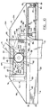
- Figure 3 is a plan view of the cooker of Figures 1 and 2.
- Figure 4 is a fragmentary side elevational view of the cooker of Figures 1-3 illustrating the vat lid in its upwardly hinged position for cleaning.
- Figure 4A is a fragmentary elevational view of the support arm latch.
- FIG. 5 is a perspective view of the vat lid with its stainless steel cover and the cam bar together with its associated arms and handle removed for purposes of clarity.
- FIG. 6 is a fragmentary plan view of the cam bar of the present invention.
- Figure 7 is a fragmentary cross-sectional view of the vat lid and its stainless steel cover.
- Figures 8-13 are fragmentary left side elevational views of one of the hook arms, the lid, the lid cover and the opening, closing and locking mechanism of the present invention, illustrating in sequence the movement of the cam bar from its forward, over-center lid locking position to its rearward unlocked and lid engaging position.
- Figure 13A is an elevational view of a window closure sheet.
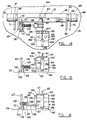
- Figure 14 is a fragmentary plan view of the cam bar and a second embodiment of the pressure-actuated cam bar latch.
- Figure 15 is a fragmentary front elevational view of the cam bar latch of Figure 14 in its unlatched condition.
- Figure 16 is a fragmentary front elevational view of the cam bar latch of Figure 14 in its latched position.
- the cooker illustrated is essentially the same as the cooker taught and illustrated in the above-noted co-pending application.
- the cooker comprises a generally rectangular housing 1 having an essentially table-top height upper surface 2.
- the housing 1 encloses a rectangular cooking vat shown in dotted lines at 3 in Figure 2, the open top 4 of which projects upwardly above the upper surface 2 of housing 1 (See also Figure 5).
- a control module 5 is mounted on the front wall of housing 1 (See Figure 1) for controlling the various functions of the cooker.
- the open top 4 of the vat 3 is adapted to be closed by a lid 6, preferably formed of cast aluminum.
- the upper portion of the lid 6 is provided with a stainless steel cover 7 affixed thereto by machine screws and having a removable upper panel 38 (See Figure 3), as will be more fully described hereinafter.
- the lid 6 has a pair of integral cast perforated lugs 9 and 9a journaled on a shaft 10. Opposite ends of the shaft 10 are received in mounting arms 11 and 12.
- the integral, rearwardly extending lid lugs 9 and 9a, together with shaft 10, form a hinge by means of which the lid 6 may be pivoted from a horizontal position to a vertical position for cleaning purposes. This is shown in Figure 4 and will be described in greater detail hereinafter.
- the lid 6 is normally maintained in a horizontal position (as shown in Figure 2) by means of studs 13 and 14 (See also Figure 5).
- the studs 13 and 14 normally lie in upwardly opening slots 15 and 16 in the mounting arms 11 and 12,
- the lid 6 is shiftable vertically between a closed position in solid lines in Figure 2 and an open position shown in broken lines in the same Figure.
- the housing 1, at its rearward end, is provided with a vertical cabinet 17 having a forward surface 18.
- the raising and lowering of lid 6 is implemented by a counterbalancing mechanism located within the cabinet 17 and fully described in the above-mentioned co-pending application.
- the mounting arms 11 and 12 extend rearwardly through slots 19 and 20 in the front surface 18 of cabinet 17 and are affixed to a frame (not shown) shiftably mounted within cabinet 17 in a pair of vertical guide rails (not shown).
- the frame is connected, through a cable and pulley system, to a vertically shiftable counterweight (not shown), chosen so as to effectively counterbalance the weight of lid 6.
- lid 6 The underside of lid 6 is provided with hangers (not shown) adapted to detachably receive a carrier (not shown) for the support of wire product-carrying trays.
- a carrier not shown
- each tray is filled with product to be cooked and then is inserted in the carrier from the front of the cooker.
- the lid 6 is shifted from its open to its closed position, the product-filled trays are lowered into vat 3.
- the carrier for the trays may be readily removed from the lid for cleaning purposes, or when it is desired to clean the lid, itself.
- the cooker will have a number of additional elements such as heating coils for the vat 3, a collection tank for spent cooking oils, various valve means and the like, together with various safety devices. These elements are known in the art and are not further discussed herein since they do not constitute a part of the present invention.
- the lid opening, closing and locking mechanism is association with the lid 6, itself, with the exception of a pair of hook arms 21 and 22.
- the hook arms 21 and 22 comprise upstanding members affixed to housing 1 on either side of the open top 4 of vat 3. Hook arm 21 is most clearly shown in Figure 4.
- the hook arm 21 is provided with a horizontal slot 23 opening rearwardly of the hook arm.
- Hook arm 22 is substantially identical to hook arm 21 and is provided with a slot 24 (See Figure 1). The purpose of hook arms 21 and 22 will be apparent hereinafter.
- the cast aluminum lid 6 has a planar top 25 and a surrounding, downwardly depending, peripheral sidewall 26.
- the inside surface of planar lid top 25 and the inside surfaces of peripheral side wall 26 may be provided with integral reinforcing ribs and the like (not shown).
- the peripheral sidewall 26 has a groove 27 formed therein which extends about the lid 6.
- the lid is provided with a planar stainless steel liner 28, the edges of which are configured to be received within the groove 27 and maintained therein by plurality of machine screws, one of which is shown in Figure 8 at 29.
- the groove 27 also receives a resilient gasket 30 adapted to make a seal with the upper edge of the open upper end 4 of vat 3.
- the sidewall 6 is inwardly stepped as at 31, forming a peripheral shoulder 32.
- the shoulder 32 supports the bottom peripheral vertical flange 33 of a stainless steel cover 7.
- the flange 33 is affixed to the lid 6 by a plurality of machine screws (not shown) which extend into the stepped portion 31 of the lid.
- the front of the cover 7 comprised a first planar panel 34 sloping upwardly and rearwardly and terminating in a second planar panel 35 which is substantially horizontal.
- a panel 36 extends upwardly and forwardly and terminates in a narrow, substantially horizontal panel 37.
- the gap between the ends of horizontal cover panel portions 35 and 37 is filled by a removable panel 38 (See Figures 3 and 7) having downwardly depending end flanges.
- the removable panel 38 is not shown in Figures 8-13.
- the stainless steel cover 7 is a unitary, one-piece structure completed by sidewalls 39 and 40.
- Sidewall 39 is shown in Figure 8.
- the sidewall 39 is inset slightly from the adjacent flange portion 33 of the cover 7.
- the sidewall 39 is planar and trapezoidal in peripheral shape.
- the sidewall has a large rectangular notch or "window" 41 formed therein having a length dimension equivalent to the width of removable panel 38.
- the purpose of window 41 will be apparent hereinafter.
- the upper end of window 41 is closed by a bar-like spacer 42, an angle iron 43, and the adjacent end flange of the removable panel 38, when mounted in position.
- the cover side 40 is a mirror image of cover side 39 and is shown in cross-section in Figure 7.
- the side 40 has a large rectangular window 44, identical to window 41.
- the cross-sectional view of Figure 7 is taken through the window 44. Again, the upper end of window 44 is closed by a bar-like spacer 45 and an angle iron 46, identical to spacer 42 and angle iron 43, together with the adjacent end flange of panel 38.
- the primary moving element of the lid opening, closing and locking mechanism of the present invention is an elongated cam bar illustrated at 47 in Figure 6.
- the cam bar 47 is of square cross-section (as perhaps can most clearly be seen from Figure 11).
- the cam bar 47 has four faces 48, 49, 50 and 51.
- the face 48 is provided with a notch 52.
- the face 49 is provided with a lug 53 containing a slot 54.
- the face 48 has two substantially identical, upstanding, rectangular lugs 55 and 56 welded or otherwise appropriately affixed thereto.
- the lugs 55 and 56 are mounted at the ends of face 48.
- cam bar 47 (as viewed in Figure 6) is the end illustrated in Figure 11. It will be noted from Figure 11 that the juncture of the cam bar faces 50 and 51 near the left end of that portion of the cam bar having a rectangular cross-section, is rounded as at 58. The juncture of faces 50 and 51 near the other end of the rectangular portion of cam bar 47 is similarly rounded (not shown). The purposes of notch 52, lug 53, lugs 55 and 56 and the rounded portions of the cam bar will be apparent hereinafter.
- cam bar 47 having a square cross-section terminates at both ends in identical cylindrical surfaces 59 and 60 (See Figure 6). Cylindrical portions 59 and 60, in turn, terminate in cylindrical portions 61 and 62 of somewhat larger diameter.
- the endmost portions 63 and 64 of the cam bar are again of cylindrical configuration having a diameter approaching that of portions 59 and 60 and less than that of portions 61 and 62.
- the endmost portions 63 and 64 support cylindrical rollers 65 and 66, respectively.
- the cylindrical rollers 65 and 66 are freely rotatable on the cam bar ends 63 and 64.
- the rollers 65 and 66 are preferably made of wear resistant plastic material such as nylon.
- rollers 65 and 66 made of a nylon material designated by the mark Nylatron GS, manufactured by Polymer Corporation, of Reading, Pennsylvania.
- the roller 65 is captively mounted on the cam bar end 63 between cam bar portion 61 and a circular plate 67 affixed to the cam bar end portion 63 by machine screw 68.
- the roller 66 is captively mounted on the end portion 64 of cam bar 47 between cam bar portion 62 and a circular plate 69 mounted with a machine screw 70.
- the cam bar 47 is completed by a pair of arms 71 and 72 welded or otherwise appropriately affixed to the cam bar portions 61 and 62, as shown in Figure 6.
- the elongated arms 71 and 72 are identical and, as is illustrated in Figure 3, their forward free ends are joined together by a bar-like member 73 constituting a handle for manipulation of cam bar 47.
- the cam bar 47, its arms 71 and 72 and the handle 73 are preferably made of stainless steel.
- FIG. 5 illustrates the lid 6 with its stainless steel cover 7 removed to expose various elements affixed to the planar upper surface 25 of lid 6.
- the individual elements next to be described cooperate in one manner or another with the cam bar 47.
- the first is a cam bar engagement means generally indicated at 74.
- the cam bar engagement means 74 is also illustrated in Figures 8-13.
- the cam bar engagement means 74 comprises a section of metallic C-channel having a central web 75 and upper and lower flanges 76 and 77.
- the cam bar engagement means 74 is centrally located near the rearward portion of lid 6, with its flanges at 76 and 77 extending toward the forward end of the lid.
- the element 74 is affixed to the lid 6 by bolt means 77a extending through the lower flange 77 and threadedly engaged in the top of lid 6.
- the next element comprises an alignment bar generally indicated at 78.
- the alignment bar comprises an elongated bar-like structure of rectangular cross-section affixed to the upper surface 25 of lid 6 by machine screws or other appropriate fastening means (not shown).
- the alignment bar 78 is located substantially centrally of top surface 25 of lid 6 and extends transversely thereof. Alignment bar 78 is also shown in broken lines in Figures 8-13.
- a right cam bar guide assembly is illustrated in Figures 5 and 7 and is generally indicated at 79.
- the right cam bar guide assembly comprises an elongated angle plate 80 having a planar horizontal plate-like leg 81 and a relatively short, upstanding planar leg 82. Near the end of angle plate 80, the upstanding leg 82 is elongated vertically, as at 83. It will be noted from Figures 5 and 7 that the upper edge of the short vertical leg portion 82 and the forward edge of the long vertical leg portion 83 are covered by protective strips of U-shaped cross-section, indicated at 84 and 85, respectively. Any appropriate wear-resistant plastic material may be used for this purpose. Excellent results have been achieved, for example, when the elements 84 and 85 were made of the above-noted Nylatron GS.
- the horizontal leg 81 of angle plate 80 is surmounted by a rectangular metallic spacer member.
- the spacer member 86 is surmounted by a block of appropriate wear-resistant plastic material such as the above-noted Nylatron GS.
- the block 87 extends over slightly less than half the length of spacer member 86 and over-hangs the spacer member at its forward edge.
- the rearward end 88 of block 87 slopes downwardly and rearwardly.
- the forward end 89 of block 87 is similarly slanted.
- forward end 89 of block 87 is not subject to wear of any sort. However, the rearward end 88 is subject to wear. Therefore, if the rearward end 88 becomes worn, the block 87 can be turned 180° so that the end 88 is replaced by the end 89.
- the angle plate 80 and the spacer member 86 are attached to the top surface 25 of lid 6 by a bolt 90.
- the block 87, spacer 86 and angle plate 80 are further attached the top surface 25 of lid 6 by bolt 91.
- a left cam bar guide assembly is generally indicated at 92.
- the left cam bar guide assembly 92 is a mirror image of the right cam bar guide assembly 79 and is otherwise identical. As a consequence, like parts of the left cam bar guide assembly 92 have been given like index numerals followed by "a".
- the left cam bar guide assembly 92 is illustrated in each of Figures 8-13.
- the final element affixed to the upper surface 25 of lid 6 comprises a cam bar latch generally indicated at 93.
- the cam bar latch 93 is also clearly shown in Figure 10.
- This structure comprises a plate-like member 94 affixed to the upper surface 25 of lid 6 by bolts, some of which are shown at 95 in Figures 5 and 10.
- the plate-like member 94 has an upstanding body portion 96.
- a locking lever 97 is affixed a pivot pin 98.
- the pivot pin is rotatively mounted on the upper end of the upstanding body portion 96 by a pair of blocks 99 and 100 affixed thereto by bolts 101 and 102.
- the locking lever 97 is freely swingable between an upwardly and rearwardly extending unlocked position (illustrated in Figures 5 and 10) and a horizontal locked position illustrated in Figure 8.
- the rearward end of the upstanding body portion 97 has a cylindrical socket 103 formed therein, wherein one end of a compression spring 104 bottoms.
- the other end of compression spring 104 abuts the bottom edge of locking lever 97 and surrounds a centering pin 105 affixed thereto.
- spring 104 locking lever 97 is biased to its unlocked position.
- the cam bar lock 93 is completed by a plunger 106 which extends through a perforation 107 in plate-like member 94 and a perforation 108 in the top of lid 6.
- the bottom end of plunger 106 is provided with an abutment block 109 which rests against the inner stainless steel liner 28 of lid 6.
- the plunger 106 is surrounded by a compression spring 110.
- One end of compression spring 110 engages abutment block 109.
- the other end of compression spring 110 abuts the inner surface of the top of lid 6. Therefore, plunger 106 is biased to its lowermost position shown in Figures 5 and 10 wherein the locking lever is in its unlocked position.
- the upper end of plunger 106 is notched as at 111 to engage the lower forward corner of locking lever 97.
- the lid liner 28 constitutes a planar stainless steel member.
- the plunger 106 is normally in its lowermost position as shown in Figures 5 and 10 and the locking lever 97 is normally in its unlocked position as shown.
- the lid liner 28 will be bowed slightly upwardly by the pressure within vat 3. This, in turn, will cause plunger 106 to shift upwardly against the action of compression spring 110.
- the uppermost end of plunger 106 will engage and shift upwardly the forward lower corner of locking lever 97, pivoting locking lever 97 to its locked condition against the action of compression spring 104 as shown in Figure 8. Pressure within vat 3 will maintain the locking lever in its locked position. Since the upper end of plunger 106 is located so close to pivot pin 98, the plunger 106 need be shifted vertically upwardly only a very short distance to cause the locking lever 97 to shift from its unlocked to its locked position.
- the cam bar 47 is shiftable manually (by means of handle 73) longitudinally of the lid 6 between a forward lid locking position and a rearward unlocking and lid engaging position. As it is shifted between these positions, the cam bar 47 is guided by engagement of its cylindrical portions 59 and 60 (see Figure 6) with the protective elements 84a and 84, respectively, of the left and right cam bar guide assemblies 92 and 79.
- Figure 8 illustrates the cam bar 47 in its forward lid locking position.
- This forward position of cam bar 47 is determined by the fact that its roller 65 is fully seated within the notch 23 of hook, arm 21. It will be understood that the cam bar roller 66 will similarly be fully seated in the notch of hook arm 22.
- the cam bar handle 73 is in its forwardmost and lowermost position, as shown in Figure 2. This positioning of handle 73 causes the cam bar 47 to assume the rotative position illustrated in Figure 8. In this rotative position, the roller 65 bears upwardly against the upper surface of hook arm notch 23, and the rounded portion 58 of the juncture of cam bar faces 50 and 51, adjacent roller 65, bears downwardly against block 87a.
- roller 66 will be bear against the upper surface of the notch 24 of hook arm 22 and the rounded juncture of cam bar surfaces 50 and 51, adjacent roller 66, will bear against block 87. Under these circumstances, the aid 6 is fully closed against the open upper end 4 of vat 3 (see Figure 2).
- cam bar 47 When the cam bar is in its forward lid locking position as illustrated in Figure 8, it will be noted that a line 112 drawn through the juncture of cam bar surfaces 48 and 49 and the juncture of cam bar surfaces 50 and 51 lies approximately 10° beyond a vertical line 113 drawn through the axis of cam bar 47.
- the cam bar 47 has assumed an over-center position locking lid 6 in its closed position with respect to the open upper end 4 of vat 3.
- vat 3 is not illustrated in Figure 8, it is to be assumed that the lid 6 is indeed in its closed and locked position with respect to the vat.
- vat is pressurized as is indicated by the slight upward bowing of the normally planar lid liner 28.
- This slight upward bowing of lid liner 28 causes the cam bar lock plunger 106 to shift upwardly against the action of compression spring 110.
- the upper end of plunger 106 in engagement with forward end of locking lever 97, causes the locking lever 97 to rotate in a counter clockwise direction about pivot pin 98 and against the action of compression spring 104.
- This causes the rearward end of locking lever 97 to engage in the notch 52 in the surface 48 of cam bar 47, precluding rotation of the cam bar 47 in a counter clockwise direction toward an unlocked position.
- the cam bar 47 cannot be shifted by its handle 73 to its rearward unlocking and lid engaging position until the cam bar, itself, is released by locking lever 97 of the cam bar lock 93.
- Figure 9 is similar to Figure 8.
- Figure 9 illustrates the cam bar in its forward lid-locking position.
- Figure 9 also illustrates release of the cam bar by the cam bar lock 93 due to depressurization of vat 3.
- Figure 12 illustrates the orientation of the cam bar 47 when the operator lowers the handle 73 to its lowermost position. It will be apparent from Figure 12 that the lowering of the handle 73 accomplishes two things. First of all, it rotates the cam bar's lugs 55 and 56 to a position clear of the studs. Secondly, it rotates the cam bar lug 53 to a position wherein its slot 54 is in alignment with the upper flange 76 of cam bar engagement means 74. With the cam bar 47 in the orientation illustrated in Figure 12, the operator can now shove the assembly rearwardly to cause the cam bar to achieve its final rearward unlocking and lid engaging position.
- the rearward unlocking and lid engaging position of the cam bar is illustrated in Figure 13.
- the maximum rearwardmost position of the cam bar is determined by abutment of the cam bar cylindrical portions 59 and 60 with the upstanding elements 85a and 85 respectively of the cam bar guide assemblies 92 and 79.
- the handle 73 of the assembly is locked in its lowermost position and the cam bar is mechanically coupled with lid 6 through the cam bar engagement means 74.
- the entire lid 6 will raise upwardly to its open position shown in broken lines in Figure 2.
- a downward force on handle 73 will cause the lid 6 to return to its closed position shown in solid lines in Figure 2. It will be remembered that vertical shifting of the lid 6 is augmented by the counterbalancing mechanism described briefly above.
- cam bar 47 To return the cam bar 47 from its rearward unlocking and lid engaging position to its forward lid locking position is accomplished by substantially repeating the above described steps in reverse.
- the operator when it is desired to shift the cam bar to its forward lid locking position, the operator need simply pull the handle forwardly. As is apparent from Figure 13, this will disengage the upper flange of cam bar engagement means 74 from the slot 54 of cam bar lug 53. Therefore, cam bar and its handle 73 are no longer mechanically coupled to the lid.
- the cam bar will shift forwardly until its face 48 engages stud 114 and its counterpart on the other side of the lid cover 7. This will serve as a tactile indication to the operator to lift the handle 73 to its uppermost position as shown in Figure 11.
- cam bar is then properly oriented to be shifted further forward to the position illustrated in Figure 10 and finally to the position illustrated in Figure 9.
- alignment bar 78 will assure proper transverse alignment of the cam bar 47 with respect to lid 6.
- the cam bar reaches the position illustrated in Figure 9, its rollers 65 and 66 are fully seated in the notches of hook arms 21 and 22, and further forward shifting of the cam bar is precluded.
- the operator need only lower the handle 73 to its lowermost position and the cam bar will assume its over-center lid-locking position illustrated in Figure 8.
- the lid opening, closing and locking mechanism of the present invention is extremely simple in construction and operation. Opening, closing and locking is accomplished by the operator through the use of a single handle and a minimum of manipulative steps. To shift the cam bar from its forward lid-locking position to its rearward unlocking and lid engaging position, the operator need only lift the handle 73, shove it rearwardly until further rearward movement is precluded by the stud 114 and its counterpart on the other side of the lid cover 7. At this point, the operator simply lowers the handle and shoves it rearwardly as far as it will go, which will assure him that he has achieved the rearward unlocking and lid engaging position.
- an elongated rectangular sheet of flexible plastic material (such as the above mentioned Nylatron GS) is provided for window 41.
- a flexible sheet is illustrated in Figure 13A at 115.
- the central portion of the sheet is provided with a circular perforation having a diameter just slightly larger than the diameter of cylindrical portion 59 of cam bar 47.
- Such a perforation is shown at 116.
- the perforation 116 is connected either to the upper edge (as shown) or to the lower edge of sheet 15 by a cut 117.
- the sheet 115 can be mounted on the cylindrical portion 59 of cam bar 47.
- the lower edge of the sheet 115 is located between the upstanding leg 82A of the left cam bar guide assembly 92 and the sidewall 39 of the stainless steel cover 7.
- the upper edge of the sheet 115 is located between the adjacent downwardly depending flange of removable panel 38 and the vertical leg of angle iron 43. In this way, that portion of sheet 115 adjacent the cam bar, itself, is guided and maintained substantially planar.
- Sheet 115 is made of such length that the window 41 will be closed thereby when the cam bar is in either its forward lid locking position or its rearward unlocking and lid engaging position.
- closure sheet 118 is located between the upstanding leg 82 of the right cam bar guide assembly 79 and the side 40 of cover 7. Similarly, the upper edge of closure sheet 118 is located between the vertical leg of angle iron 46 and the adjacent downwardly depending flange of removable panel 38.
- the lid 6 is capable of achieving a vertical position (as shown in Figure 4) during cleaning of the cooker. It will be remembered that lid 6 is hingedly mounted with respect to mounting arms 11 and 12 by virtue of shaft 10 and lid lugs 9 and 9a. The lid 6 normally is maintained in a horizontal position as shown in Figure 2 by virtue of the receipt of studs 13 and 14 within upwardly opening slots 15 and 16 in the mounting arms 11 and 12. When cam bar 47 is in its rearward unlocking and lid engaging position described with respect to Figure 13, an upward force on handle 73 will cause the lid to shift vertically upwardly as shown in Figure 2, by virtue of the counterbalancing mechanism.
- the mounting arm latch means is mounted on the forward face 18 of cabinet 17.
- the mounting arm latch means is illustrated in Figure 4A.
- the mounting arm latch means comprises a bracket 118 affixed to the forward panel 18 of cabinet 17 by bolts 119, or the like.
- the bracket 118 has a central semi-cylindrical portion 120.
- the latch is completed by a rod-like member 121 formed into a U-shape.
- the base 122 of the member 121 is pivotally mounted in the semi-cylindrical portion 120 of bracket 118. It will be noted from Figure 4A that the upper leg 123 of the U-shaped member 121 is longer than the lower leg 124 thereof.
- the U-shaped member 121 is shown in solid lines in its inoperative position.
- the member 121 can be rotated to an operative position shown in Figure 4A in broken lines.
- the upper leg 123 of the member 121 extends across the slot 19 in the forward panel 18 of cabinet 17.
- the support arm 11 cannot shift vertically. Since the support arm 12 is mounted on the same frame as support arm 11, it too is effectively locked against vertical movement.
- the latch element 121 in the position shown in broken lines in Figure 4A, the operator need only apply a lifting force to handle 73, and the lid 6 will assume its vertical position shown in Figure 4.
- a plate-like magnet is mounted on the inside surface of the front panel 18 of cabinet 17.
- the cabinet magnet is indicated in broken lines at 125 in Figure 1.
- a plate-like magnet 126 is mounted on the inside surface of panel 34 of lid cover 7.
- FIGs 14-16 illustrate a modification to cam bar lock 93 which renders it even more positive.
- cam bar 47 is shown and the same index numerals have been used as were used in Figure 6.
- the cam bar 47 of Figure 14 is identical to cam bar 47 of Figure 6 with the exception that an additional lug 127 has been mounted thereon.
- the lug 127 is identical to lugs 55 and 56, with the exception that it is provided with a transverse perforation 128.
- the angle bracket 129 has a horizontal leg 130 affixed to the surface 125 by bolts 131, or the like.
- Angle bracket 129 has an upstanding leg 132 provided with a transverse perforation 133.
- the cam bar lock 93 is identical to that described above, and like parts have been given like index numerals.
- a shaft 134 is welded to the side of block 99 of the cam bar lock 93.
- the shaft 134 is substantially parallel to the top surface 25 of lid 6 and extends rearwardly toward cam bar 47.
- the shaft 134 rotatively mounts a substantially triangular, bifurcated lever 135.
- the pin 134 passes through a perforation in the triangular lever 134 near one of its corners. It will be apparent from the figures that another of its corners underlies locking lever 97.
- the third corner of lever 135 depends downwardly and the bifurcations are provided with coaxial perforations, one of which is shown at 136.
- the perforation 136 and its counterpart in the other bifurcation receive a transverse pin 137 mounted in a rod 138 which extends between the bifurcations. In this way, the lever 135 and the rod 138 have a pivotal relationship.
- the free end of rod 138 has a second rod 139 welded thereto.
- the end of rod 39 opposite the welded end is supported in the perforation 133 of the upstanding leg 132 of angle bracket 129.
- the rod 139 supports a washer 140.
- Rod 139 is surrounded by a compression spring 141.
- One end of the compression spring 141 abuts washer 140.
- the other end of compression spring 141 abuts upstanding angle bracket leg 132.
- cam bar 47 When, however, cam bar 47 is in its forward lid-locking position, and when the vat is pressurized to cause the locking lever 97 of cam bar lock 93 to move downwardly and engage the notch 52 of cam bar 47 (as described with respect to Figure 8), the locking lever 97 will actuate the additional lock parts. Thus, downward movement of locking lever 97 will shift the triangular lever 135 and the rod-like assembly 138-139 to the position shown in Figure 16, against the action of compression spring 141. In the position shown in Figure 16, the rod-like element 139 passes through the perforation 128 of cam bar lug 127 positively locking the cam bar against rotative movement.
Landscapes
- Engineering & Computer Science (AREA)
- Food Science & Technology (AREA)
- Cookers (AREA)
- Frying-Pans Or Fryers (AREA)
- Commercial Cooking Devices (AREA)
- Closures For Containers (AREA)
Description
- The present invention teaches improvements with respect to large capacity pressure cookers of the type set forth in co-pending U.S Patent application Serial No. 07/283,571, filed December 13, 1988, in the names of James D. King and Stephen D. Werts, and entitled LARGE CAPACITY PRESSURE COOKER.
- The invention relates to mechanism for opening, closing and locking the vat lid of a large capacity pressure cooker, and more particularly to such a mechanism which employs a single handle, is simple in construction and operation, and requires a minimum of manipulation by the operator.
- Pressure cookers generally comprise a vat or cooking vessel of a size to receive a wire basket in which the product to be cooked is placed and then immersed in the cooking oil contained in the vat. The vat is closed by a lid which is sealed to the top of the vat, whereupon the product is cooked for the desired length of time under both heat and pressure. Following the cooking cycle, the pressure in the vat is relieved and the lid is opened, whereupon the product is removed from the wire basket.
- The type of large capacity pressure cooker to which the present invention is directed is illustrated and described in the above noted co-pending U.S. Patent application, the teachings of which are incorporated herein by reference. During the cooking operation, when the vat is pressurized, it is imperative that the vat lid be firmly closed and locked, as a matter of safety.
- It will be appreciated that the vat lid and its associated mechanism is large and heavy making it difficult to shift the lid vertically between its open and closed positions. Prior art workers have devised counter balancing mechanisms to alleviate this problem. Nevertheless, the prior art large capacity pressure cookers are characterized by very complex lid opening, closing and leveling means which require considerable operator manipulation of a series of elements. Many of the opening, closing and locking mechanisms are such that it is impractical for the cookers to be operated by personnel lacking the size and physical strength to cope with the rigors of manual operations required to operate the equipment. Some require manipulation of a first handle for raising and lowering the lid, and manipulation of a second handle for locking the lid in its closed position.
- US-A-4798939 teaches a large capacity pressure cooker having a vat provided with a lid which forms a seal with the upper open end of the vat. The lid is attached to a clamping bar by a cam mechanism. One end of the clamping bar is hinged to the vat. The other end of the clamping bar is provided with a hook-like latch adapted to engage a pin mounted on the vat. The lid is closed by shifting the clamping bar to its closed position. The hook-like latch of the clamping bar is positioned to engage the vat pin. The cam mechanism by which the lid is attached to the clamping bar comprises a cam and a handle. When the cam handle is shifted from an open position to a closed position, the cam engages the lid, applying a downward force on the lid. Simultaneously, the cam applies an upward force on the clamping bar, bringing its hook-like latch into engagement with the vat pin. The lid unit also features a pressure interlock comprising a vertically extending piston and cylinder which extends vertically through the lid, When pressure builds up in the vat, the piston of the interlock cylinder shifts upwardly to a position wherein it lies adjacent a laterally extending pin mounted on the cam handle. When the interlock piston is in this position, the cam handle cannot be shifted to its open position.
- The above construction is typical of exemplary lid and lid locking mechanisms of the prior art, but it differs markedly from the lid and locking mechanism of the present application. The prior art lid is not supported by vertically shiftable arms and opens only by rotating from a horizontal position to a vertical position. The locking mechanism involves two handles and is wholly unlike that of the present invention, as is the pressure interlock unit.
- The present invention provides a large capacity pressure cooker capable of handling, for example, 10 heads of chicken, while at the same time providing a lid opening, closing and locking mechanism which can be operated by the average worker without undue physical exertion and with a minimum of manipulation. The lid opening, closing and locking mechanism is operated by a single handle and is simpler in construction and operation than those of the prior art. In addition, positive means are provided to preclude mistaken unlocking and opening of the vat lid while the vat is pressurized.
- According to the invention as laid down in claim 1, there is provided a single handle-actuated lid opening, closing and locking mechanism for a large capacity pressure cooker. The pressure cooker has an open-top cooking vat and a counter balanced lid liftable vertically between vat open and vat closed positions.
- The mechanism comprises a pair of slotted hook arms mounted to either side of the vat and a cam bar which is mounted on and extends transversely of the vat lid. The cam bar is provided with forwardly extending arms near its ends. The forward ends of the arms are joined by a bar comprising a handle in parallel spaced relationship to the cam bar. The ends of the cam bar support rollers receivable within the slots of the hook arms. The main body portion of the cam bar is of non-circular cross-section.
- The cam bar is manually shiftable longitudinally of the lid by the handle, between a forward lid locking position and a rearward unlocking and lid engaging position. Guide means are provided to assure proper shifting of the cam bar. In its forward lid locking position, the cam bar assumes an over-center orientation with its rollers bearing upwardly against the upper surfaces of the hook arm slots, and the main body portion of the cam bar bearing downwardly against the lid. In its rearward unlocked and lid engaging position, the cam bar is rigidly coupled to the lid so that upward and downward forces applied to the handle result in vertical upward and downward movement of the lid between its vat open and its vat closed positions. A cam bar lock is provided which precludes unlocking and opening of the lid while the vat is pressurized.
- Figure 1 is a front elevational view of an exemplary large capacity pressure cooker provided with the lid opening, closing and locking mechanism of the present invention.
- Figure 2 is a side elevational view of the cooker of Figure 1 as seen from the left side of that figure.
- Figure 3 is a plan view of the cooker of Figures 1 and 2.
- Figure 4 is a fragmentary side elevational view of the cooker of Figures 1-3 illustrating the vat lid in its upwardly hinged position for cleaning.
- Figure 4A is a fragmentary elevational view of the support arm latch.
- Figure 5 is a perspective view of the vat lid with its stainless steel cover and the cam bar together with its associated arms and handle removed for purposes of clarity.
- Figure 6 is a fragmentary plan view of the cam bar of the present invention.
- Figure 7 is a fragmentary cross-sectional view of the vat lid and its stainless steel cover.
- Figures 8-13 are fragmentary left side elevational views of one of the hook arms, the lid, the lid cover and the opening, closing and locking mechanism of the present invention, illustrating in sequence the movement of the cam bar from its forward, over-center lid locking position to its rearward unlocked and lid engaging position.
- Figure 13A is an elevational view of a window closure sheet.
- Figure 14 is a fragmentary plan view of the cam bar and a second embodiment of the pressure-actuated cam bar latch.
- Figure 15 is a fragmentary front elevational view of the cam bar latch of Figure 14 in its unlatched condition.
- Figure 16 is a fragmentary front elevational view of the cam bar latch of Figure 14 in its latched position.
- Referring first to Figures 1-4, the cooker illustrated is essentially the same as the cooker taught and illustrated in the above-noted co-pending application. To this end, the cooker comprises a generally rectangular housing 1 having an essentially table-top height
upper surface 2. The housing 1 encloses a rectangular cooking vat shown in dotted lines at 3 in Figure 2, theopen top 4 of which projects upwardly above theupper surface 2 of housing 1 (See also Figure 5). Acontrol module 5 is mounted on the front wall of housing 1 (See Figure 1) for controlling the various functions of the cooker. - The
open top 4 of thevat 3 is adapted to be closed by alid 6, preferably formed of cast aluminum. The upper portion of thelid 6 is provided with astainless steel cover 7 affixed thereto by machine screws and having a removable upper panel 38 (See Figure 3), as will be more fully described hereinafter. Thelid 6 has a pair of integral cast perforatedlugs shaft 10. Opposite ends of theshaft 10 are received in mountingarms shaft 10, form a hinge by means of which thelid 6 may be pivoted from a horizontal position to a vertical position for cleaning purposes. This is shown in Figure 4 and will be described in greater detail hereinafter. Thelid 6 is normally maintained in a horizontal position (as shown in Figure 2) by means ofstuds 13 and 14 (See also Figure 5). Thestuds slots arms - The
lid 6 is shiftable vertically between a closed position in solid lines in Figure 2 and an open position shown in broken lines in the same Figure. The housing 1, at its rearward end, is provided with avertical cabinet 17 having aforward surface 18. The raising and lowering oflid 6 is implemented by a counterbalancing mechanism located within thecabinet 17 and fully described in the above-mentioned co-pending application. Briefly, the mountingarms slots front surface 18 ofcabinet 17 and are affixed to a frame (not shown) shiftably mounted withincabinet 17 in a pair of vertical guide rails (not shown). The frame is connected, through a cable and pulley system, to a vertically shiftable counterweight (not shown), chosen so as to effectively counterbalance the weight oflid 6. - The underside of
lid 6 is provided with hangers (not shown) adapted to detachably receive a carrier (not shown) for the support of wire product-carrying trays. As is described in the above-noted co-pending application, each tray is filled with product to be cooked and then is inserted in the carrier from the front of the cooker. When thelid 6 is shifted from its open to its closed position, the product-filled trays are lowered intovat 3. The carrier for the trays may be readily removed from the lid for cleaning purposes, or when it is desired to clean the lid, itself. - It will be understood by one skilled in the art that the cooker will have a number of additional elements such as heating coils for the
vat 3, a collection tank for spent cooking oils, various valve means and the like, together with various safety devices. These elements are known in the art and are not further discussed herein since they do not constitute a part of the present invention. - As indicated above, the invention is directed to an improved lid opening, closing and locking mechanism which will now be described. The lid opening, closing and locking mechanism is association with the
lid 6, itself, with the exception of a pair ofhook arms hook arms open top 4 ofvat 3.Hook arm 21 is most clearly shown in Figure 4. Thehook arm 21 is provided with ahorizontal slot 23 opening rearwardly of the hook arm.Hook arm 22 is substantially identical to hookarm 21 and is provided with a slot 24 (See Figure 1). The purpose ofhook arms - Reference is made to Figures 5 and 8. The
cast aluminum lid 6 has a planar top 25 and a surrounding, downwardly depending,peripheral sidewall 26. The inside surface ofplanar lid top 25 and the inside surfaces ofperipheral side wall 26 may be provided with integral reinforcing ribs and the like (not shown). Theperipheral sidewall 26 has agroove 27 formed therein which extends about thelid 6. The lid is provided with a planarstainless steel liner 28, the edges of which are configured to be received within thegroove 27 and maintained therein by plurality of machine screws, one of which is shown in Figure 8 at 29. Thegroove 27 also receives aresilient gasket 30 adapted to make a seal with the upper edge of the openupper end 4 ofvat 3. - As is most clearly shown in Figure 5, the
sidewall 6 is inwardly stepped as at 31, forming aperipheral shoulder 32. Theshoulder 32 supports the bottom peripheralvertical flange 33 of astainless steel cover 7. Theflange 33 is affixed to thelid 6 by a plurality of machine screws (not shown) which extend into the steppedportion 31 of the lid. - From the
flange 33, the front of thecover 7 comprised a firstplanar panel 34 sloping upwardly and rearwardly and terminating in a secondplanar panel 35 which is substantially horizontal. At the rear ofcover 7, apanel 36 extends upwardly and forwardly and terminates in a narrow, substantiallyhorizontal panel 37. The gap between the ends of horizontalcover panel portions removable panel 38 is not shown in Figures 8-13. - With the exception of
removable panel 38, thestainless steel cover 7 is a unitary, one-piece structure completed by sidewalls 39 and 40.Sidewall 39 is shown in Figure 8. Thesidewall 39 is inset slightly from theadjacent flange portion 33 of thecover 7. Thesidewall 39 is planar and trapezoidal in peripheral shape. The sidewall has a large rectangular notch or "window" 41 formed therein having a length dimension equivalent to the width ofremovable panel 38. The purpose ofwindow 41 will be apparent hereinafter. The upper end ofwindow 41 is closed by a bar-like spacer 42, anangle iron 43, and the adjacent end flange of theremovable panel 38, when mounted in position. - The
cover side 40 is a mirror image ofcover side 39 and is shown in cross-section in Figure 7. Theside 40 has a largerectangular window 44, identical towindow 41. The cross-sectional view of Figure 7 is taken through thewindow 44. Again, the upper end ofwindow 44 is closed by a bar-like spacer 45 and an angle iron 46, identical tospacer 42 andangle iron 43, together with the adjacent end flange ofpanel 38. - The primary moving element of the lid opening, closing and locking mechanism of the present invention is an elongated cam bar illustrated at 47 in Figure 6. For the majority of its length, the
cam bar 47 is of square cross-section (as perhaps can most clearly be seen from Figure 11). As a result of the square cross-section, thecam bar 47 has four faces 48, 49, 50 and 51. Theface 48 is provided with anotch 52. Theface 49 is provided with alug 53 containing aslot 54. Theface 48 has two substantially identical, upstanding,rectangular lugs lugs face 48. - The left-hand end of cam bar 47 (as viewed in Figure 6) is the end illustrated in Figure 11. It will be noted from Figure 11 that the juncture of the cam bar faces 50 and 51 near the left end of that portion of the cam bar having a rectangular cross-section, is rounded as at 58. The juncture of
faces cam bar 47 is similarly rounded (not shown). The purposes ofnotch 52,lug 53, lugs 55 and 56 and the rounded portions of the cam bar will be apparent hereinafter. - The main body portion of
cam bar 47 having a square cross-section terminates at both ends in identicalcylindrical surfaces 59 and 60 (See Figure 6).Cylindrical portions cylindrical portions endmost portions portions portions endmost portions cylindrical rollers cylindrical rollers rollers rollers roller 65 is captively mounted on thecam bar end 63 betweencam bar portion 61 and acircular plate 67 affixed to the cambar end portion 63 bymachine screw 68. In similar fashion, theroller 66 is captively mounted on theend portion 64 ofcam bar 47 betweencam bar portion 62 and acircular plate 69 mounted with amachine screw 70. - The
cam bar 47 is completed by a pair ofarms cam bar portions elongated arms like member 73 constituting a handle for manipulation ofcam bar 47. Thecam bar 47, itsarms handle 73 are preferably made of stainless steel. - Reference is now made to Figure 5. It will be remembered that Figure 5 illustrates the
lid 6 with itsstainless steel cover 7 removed to expose various elements affixed to the planarupper surface 25 oflid 6. The individual elements next to be described cooperate in one manner or another with thecam bar 47. The first is a cam bar engagement means generally indicated at 74. The cam bar engagement means 74 is also illustrated in Figures 8-13. The cam bar engagement means 74 comprises a section of metallic C-channel having acentral web 75 and upper andlower flanges lid 6, with its flanges at 76 and 77 extending toward the forward end of the lid. Theelement 74 is affixed to thelid 6 by bolt means 77a extending through thelower flange 77 and threadedly engaged in the top oflid 6. - The next element comprises an alignment bar generally indicated at 78. The alignment bar comprises an elongated bar-like structure of rectangular cross-section affixed to the
upper surface 25 oflid 6 by machine screws or other appropriate fastening means (not shown). Thealignment bar 78 is located substantially centrally oftop surface 25 oflid 6 and extends transversely thereof.Alignment bar 78 is also shown in broken lines in Figures 8-13. - A right cam bar guide assembly is illustrated in Figures 5 and 7 and is generally indicated at 79. The right cam bar guide assembly comprises an
elongated angle plate 80 having a planar horizontal plate-like leg 81 and a relatively short, upstandingplanar leg 82. Near the end ofangle plate 80, theupstanding leg 82 is elongated vertically, as at 83. It will be noted from Figures 5 and 7 that the upper edge of the shortvertical leg portion 82 and the forward edge of the longvertical leg portion 83 are covered by protective strips of U-shaped cross-section, indicated at 84 and 85, respectively. Any appropriate wear-resistant plastic material may be used for this purpose. Excellent results have been achieved, for example, when theelements - The
horizontal leg 81 ofangle plate 80 is surmounted by a rectangular metallic spacer member. Thespacer member 86, in turn, is surmounted by a block of appropriate wear-resistant plastic material such as the above-noted Nylatron GS. It will be noted that theblock 87 extends over slightly less than half the length ofspacer member 86 and over-hangs the spacer member at its forward edge. Therearward end 88 ofblock 87 slopes downwardly and rearwardly. Theforward end 89 ofblock 87 is similarly slanted. As will be apparent hereinafter, forward end 89 ofblock 87 is not subject to wear of any sort. However, therearward end 88 is subject to wear. Therefore, if therearward end 88 becomes worn, theblock 87 can be turned 180° so that theend 88 is replaced by theend 89. - The
angle plate 80 and thespacer member 86 are attached to thetop surface 25 oflid 6 by abolt 90. In similar fashion, theblock 87,spacer 86 andangle plate 80 are further attached thetop surface 25 oflid 6 bybolt 91. - A left cam bar guide assembly is generally indicated at 92. The left cam
bar guide assembly 92 is a mirror image of the right cam bar guide assembly 79 and is otherwise identical. As a consequence, like parts of the left cambar guide assembly 92 have been given like index numerals followed by "a". The left cambar guide assembly 92 is illustrated in each of Figures 8-13. - The final element affixed to the
upper surface 25 oflid 6 comprises a cam bar latch generally indicated at 93. Thecam bar latch 93 is also clearly shown in Figure 10. This structure comprises a plate-like member 94 affixed to theupper surface 25 oflid 6 by bolts, some of which are shown at 95 in Figures 5 and 10. The plate-like member 94 has anupstanding body portion 96. A lockinglever 97 is affixed apivot pin 98. The pivot pin is rotatively mounted on the upper end of theupstanding body portion 96 by a pair ofblocks bolts lever 97 is freely swingable between an upwardly and rearwardly extending unlocked position (illustrated in Figures 5 and 10) and a horizontal locked position illustrated in Figure 8. The rearward end of theupstanding body portion 97 has acylindrical socket 103 formed therein, wherein one end of acompression spring 104 bottoms. The other end ofcompression spring 104 abuts the bottom edge of lockinglever 97 and surrounds a centeringpin 105 affixed thereto. By virtue ofspring 104, lockinglever 97 is biased to its unlocked position. - The
cam bar lock 93 is completed by aplunger 106 which extends through aperforation 107 in plate-like member 94 and aperforation 108 in the top oflid 6. The bottom end ofplunger 106 is provided with anabutment block 109 which rests against the innerstainless steel liner 28 oflid 6. Theplunger 106 is surrounded by acompression spring 110. One end ofcompression spring 110 engagesabutment block 109. The other end ofcompression spring 110 abuts the inner surface of the top oflid 6. Therefore,plunger 106 is biased to its lowermost position shown in Figures 5 and 10 wherein the locking lever is in its unlocked position. The upper end ofplunger 106 is notched as at 111 to engage the lower forward corner of lockinglever 97. - Under normal circumstances, the
lid liner 28 constitutes a planar stainless steel member. Theplunger 106 is normally in its lowermost position as shown in Figures 5 and 10 and the lockinglever 97 is normally in its unlocked position as shown. However, when thelid 6 is in its closed and latched position, and thevat 3 is pressurized during a cooking cycle, thelid liner 28 will be bowed slightly upwardly by the pressure withinvat 3. This, in turn, will causeplunger 106 to shift upwardly against the action ofcompression spring 110. The uppermost end ofplunger 106 will engage and shift upwardly the forward lower corner of lockinglever 97, pivoting lockinglever 97 to its locked condition against the action ofcompression spring 104 as shown in Figure 8. Pressure withinvat 3 will maintain the locking lever in its locked position. Since the upper end ofplunger 106 is located so close to pivotpin 98, theplunger 106 need be shifted vertically upwardly only a very short distance to cause the lockinglever 97 to shift from its unlocked to its locked position. - The basic elements of the lid opening, closing and locking mechanism having been described, the manner in which they operate will now be set forth. In Figure 8, the
cover 7 is shown mounted onlid 6. When the mechanism is fully assembled, thecam bar 47 extends transversely oflid 6. The ends of the cam bar including thearms rollers windows - The
cam bar 47 is shiftable manually (by means of handle 73) longitudinally of thelid 6 between a forward lid locking position and a rearward unlocking and lid engaging position. As it is shifted between these positions, thecam bar 47 is guided by engagement of itscylindrical portions 59 and 60 (see Figure 6) with theprotective elements bar guide assemblies 92 and 79. - Figure 8 illustrates the
cam bar 47 in its forward lid locking position. This forward position ofcam bar 47 is determined by the fact that itsroller 65 is fully seated within thenotch 23 of hook,arm 21. It will be understood that thecam bar roller 66 will similarly be fully seated in the notch ofhook arm 22. The cam bar handle 73 is in its forwardmost and lowermost position, as shown in Figure 2. This positioning ofhandle 73 causes thecam bar 47 to assume the rotative position illustrated in Figure 8. In this rotative position, theroller 65 bears upwardly against the upper surface ofhook arm notch 23, and the roundedportion 58 of the juncture of cam bar faces 50 and 51,adjacent roller 65, bears downwardly againstblock 87a. In similar fashion it will be understood that theroller 66 will be bear against the upper surface of thenotch 24 ofhook arm 22 and the rounded juncture of cam bar surfaces 50 and 51,adjacent roller 66, will bear againstblock 87. Under these circumstances, theaid 6 is fully closed against the openupper end 4 of vat 3 (see Figure 2). - When the
cam bar 47 is in its forward lid locking position, itscylindrical portions elements bar guide assemblies 92 and 79, respectively. This is the result of compression of theresilient gasket 30 by the openupper end 4 ofvat 3. - When the cam bar is in its forward lid locking position as illustrated in Figure 8, it will be noted that a
line 112 drawn through the juncture of cam bar surfaces 48 and 49 and the juncture of cam bar surfaces 50 and 51 lies approximately 10° beyond avertical line 113 drawn through the axis ofcam bar 47. Thus thecam bar 47 has assumed an over-centerposition locking lid 6 in its closed position with respect to the openupper end 4 ofvat 3. - During the cooking cycle, when the
lid 6 is closed and locked with respect to the openupper end 4 ofvat 3, the vat is thereafter pressurized. To prevent injury to the operator, it is important that thelid 6 cannot mistakenly be opened while thevat 3 is pressurized. This is the function ofcam bar lock 93 which automatically locks thecam bar 47 in the position shown in Figure 8 while thevat 3 is pressurized. The manner in which this is accomplished is illustrated in Figure 8. - While the
vat 3 is not illustrated in Figure 8, it is to be assumed that thelid 6 is indeed in its closed and locked position with respect to the vat. - It is further to be assumed that the vat is pressurized as is indicated by the slight upward bowing of the normally
planar lid liner 28. This slight upward bowing oflid liner 28 causes the cambar lock plunger 106 to shift upwardly against the action ofcompression spring 110. The upper end ofplunger 106, in engagement with forward end of lockinglever 97, causes the lockinglever 97 to rotate in a counter clockwise direction aboutpivot pin 98 and against the action ofcompression spring 104. This, in turn, causes the rearward end of lockinglever 97 to engage in thenotch 52 in thesurface 48 ofcam bar 47, precluding rotation of thecam bar 47 in a counter clockwise direction toward an unlocked position. As a consequence, thecam bar 47 cannot be shifted by itshandle 73 to its rearward unlocking and lid engaging position until the cam bar, itself, is released by lockinglever 97 of thecam bar lock 93. - Figure 9 is similar to Figure 8. Figure 9 illustrates the cam bar in its forward lid-locking position. Figure 9 also illustrates release of the cam bar by the
cam bar lock 93 due to depressurization ofvat 3. - When the
vat 3 is depressurized, thelid liner 28 will return to its normal, planar, horizontal condition as shown in Figure 9. This will enable theplunger 106 of thecam bar lock 93 to shift downwardly with theliner 28, under the influence ofcompression spring 110. As the cambar lock plunger 106 shifts downwardly, the lockinglever 97 will move with it, rotating in a clockwise direction aboutpivot pin 98 under the influence ofcompression spring 104. As a result, the cam bar lock is in its unlocked condition andcam bar 47 can now be shifted by the operator from its forward lid locking position to its rearward unlocking and lid engaging position. The steps involved in this shift are illustrated in Figures 10-13. - Reference is first made to Figure 10. As a first step in shifting the
cam bar 47 from its forward lid locking position to its rearward unlocking and lid engaging position, the operator lifts thehandle 73 to its uppermost position. This causes rearward shifting and counter clockwise rotation of the cam bar to the position shown in Figure 10. This position of the cam bar and the uppermost position of thehandle 73 are determined by abutment ofcam bar lug 55 against the horizontal leg ofangle iron 43. It will be understood that thecam bar lug 56 will similarly abut against the horizontal leg of angle iron 46 (see Figure 7). At this point, the force compressing thelid gasket 30 is released and thecylindrical portions elements bar guide assemblies 92 and 79. - Having raised the
handle 73 to its uppermost position, the next step performed by the operator is to shift the raised handle rearwardly. This is illustrated in Figure 11. The assembly ofspacer 42 andangle iron 43 supports an inwardly extendingstud 114. Thecam bar 47 shifts rearwardly until itslug 55 contacts thestud 114. It will be understood that the assembly of thespacer 45 and angle iron 46 (see Figure 7) also support a stud (not shown) equivalent tostud 114. This last mentioned stud is contacted by thecam bar lug 56. The studs are located directly across from each other so that when contacted, thecam bar 47 remains in its transverse orientation with respect to thelid 6. Whencam bar 47 reaches the position illustrated in Figure 11, further rearward movement of the cam bar is precluded by the studs and this serves as a tactile signal to the operator to return thehandle 73 to its lowermost position. - Figure 12 illustrates the orientation of the
cam bar 47 when the operator lowers thehandle 73 to its lowermost position. It will be apparent from Figure 12 that the lowering of thehandle 73 accomplishes two things. First of all, it rotates the cam bar'slugs cam bar lug 53 to a position wherein itsslot 54 is in alignment with theupper flange 76 of cam bar engagement means 74. With thecam bar 47 in the orientation illustrated in Figure 12, the operator can now shove the assembly rearwardly to cause the cam bar to achieve its final rearward unlocking and lid engaging position. - The rearward unlocking and lid engaging position of the cam bar is illustrated in Figure 13. The maximum rearwardmost position of the cam bar is determined by abutment of the cam bar
cylindrical portions upstanding elements bar guide assemblies 92 and 79. When theupper flange 76 of the cam bar engagement means 74 enters theslot 54 ofcam bar lug 53, thehandle 73 of the assembly is locked in its lowermost position and the cam bar is mechanically coupled withlid 6 through the cam bar engagement means 74. As a consequence, if the operator lifts upwardly onhandle 73, theentire lid 6 will raise upwardly to its open position shown in broken lines in Figure 2. A downward force onhandle 73 will cause thelid 6 to return to its closed position shown in solid lines in Figure 2. It will be remembered that vertical shifting of thelid 6 is augmented by the counterbalancing mechanism described briefly above. - To return the
cam bar 47 from its rearward unlocking and lid engaging position to its forward lid locking position is accomplished by substantially repeating the above described steps in reverse. Returning to Figure 13, when it is desired to shift the cam bar to its forward lid locking position, the operator need simply pull the handle forwardly. As is apparent from Figure 13, this will disengage the upper flange of cam bar engagement means 74 from theslot 54 ofcam bar lug 53. Therefore, cam bar and itshandle 73 are no longer mechanically coupled to the lid. The cam bar will shift forwardly until itsface 48 engagesstud 114 and its counterpart on the other side of thelid cover 7. This will serve as a tactile indication to the operator to lift thehandle 73 to its uppermost position as shown in Figure 11. The cam bar is then properly oriented to be shifted further forward to the position illustrated in Figure 10 and finally to the position illustrated in Figure 9. As the cam bar is rotated by upward movement ofhandle 73 and simultaneously shifted forwardly, it will momentarily contactalignment bar 78 which will assure proper transverse alignment of thecam bar 47 with respect tolid 6. When the cam bar reaches the position illustrated in Figure 9, itsrollers hook arms handle 73 to its lowermost position and the cam bar will assume its over-center lid-locking position illustrated in Figure 8. - From the above, it will be apparent that the lid opening, closing and locking mechanism of the present invention is extremely simple in construction and operation. Opening, closing and locking is accomplished by the operator through the use of a single handle and a minimum of manipulative steps. To shift the cam bar from its forward lid-locking position to its rearward unlocking and lid engaging position, the operator need only lift the
handle 73, shove it rearwardly until further rearward movement is precluded by thestud 114 and its counterpart on the other side of thelid cover 7. At this point, the operator simply lowers the handle and shoves it rearwardly as far as it will go, which will assure him that he has achieved the rearward unlocking and lid engaging position. To shift from the rearward unlocking and lid engaging position to the forward lid locking position, the operator need only pull the handle forwardly until further forward movement is precluded by thestud 114 and its counterpart. At this point, the operator raises the handle to its uppermost position and pulls forwardly until further forward movement is precluded by thecam bar rollers hook arms lid 6 has achieved its fully closed and over-center locked position with respect to the openupper end 4 ofvat 3. - To maintain the chamber formed by the
upper surface 25 oflid 6 and thestainless steel cover 7, clean and free of grease, contamination and the like, it is preferable that means be provided to maintain thewindows cam bar 47. To this end, an elongated rectangular sheet of flexible plastic material (such as the above mentioned Nylatron GS) is provided forwindow 41. Such a flexible sheet is illustrated in Figure 13A at 115. The central portion of the sheet is provided with a circular perforation having a diameter just slightly larger than the diameter ofcylindrical portion 59 ofcam bar 47. Such a perforation is shown at 116. Theperforation 116 is connected either to the upper edge (as shown) or to the lower edge ofsheet 15 by acut 117. Through the agency ofcut 117, thesheet 115 can be mounted on thecylindrical portion 59 ofcam bar 47. The lower edge of thesheet 115, as viewed in Figure 13A, is located between the upstanding leg 82A of the left cambar guide assembly 92 and thesidewall 39 of thestainless steel cover 7. The upper edge of thesheet 115, as viewed in Figure 13A, is located between the adjacent downwardly depending flange ofremovable panel 38 and the vertical leg ofangle iron 43. In this way, that portion ofsheet 115 adjacent the cam bar, itself, is guided and maintained substantially planar.Sheet 115 is made of such length that thewindow 41 will be closed thereby when the cam bar is in either its forward lid locking position or its rearward unlocking and lid engaging position. When the cam bar is in its rearward unlocking and lid engaging position, the left hand end ofsheet 115 as viewed in Figure 13A is simply caused to bend inwardly by the slopingpanel 36 ofstainless steel cover 7. Similarly, when thecam bar 47 is in its forward lid locking position, the right end ofsheet 115, as viewed in Figure 13A, is caused to bend inwardly by the slopingpanel 34 ofstainless steel cover 7. - The
window 44 on the opposite side ofstainless steel cover 7 is similarly provided with a substantiallyidentical closure sheet 118. This closure sheet is illustrated in Figure 7 and it will be noted that the bottom edge ofclosure sheet 118 is located between theupstanding leg 82 of the right cam bar guide assembly 79 and theside 40 ofcover 7. Similarly, the upper edge ofclosure sheet 118 is located between the vertical leg of angle iron 46 and the adjacent downwardly depending flange ofremovable panel 38. - As briefly described above with respect to Figure 4, the
lid 6 is capable of achieving a vertical position (as shown in Figure 4) during cleaning of the cooker. It will be remembered thatlid 6 is hingedly mounted with respect to mountingarms shaft 10 and lid lugs 9 and 9a. Thelid 6 normally is maintained in a horizontal position as shown in Figure 2 by virtue of the receipt ofstuds slots arms cam bar 47 is in its rearward unlocking and lid engaging position described with respect to Figure 13, an upward force onhandle 73 will cause the lid to shift vertically upwardly as shown in Figure 2, by virtue of the counterbalancing mechanism. However, if the mountingarms handle 73 will cause the lid to pivot aboutshaft 10, assuming its vertical position shown in Figure 4. To this end, a mounting arm latch means is mounted on theforward face 18 ofcabinet 17. The mounting arm latch means is illustrated in Figure 4A. The mounting arm latch means comprises abracket 118 affixed to theforward panel 18 ofcabinet 17 bybolts 119, or the like. Thebracket 118 has a centralsemi-cylindrical portion 120. The latch is completed by a rod-like member 121 formed into a U-shape. Thebase 122 of the member 121 is pivotally mounted in thesemi-cylindrical portion 120 ofbracket 118. It will be noted from Figure 4A that theupper leg 123 of the U-shaped member 121 is longer than thelower leg 124 thereof. - In Figure 4A, the U-shaped member 121 is shown in solid lines in its inoperative position. The member 121 can be rotated to an operative position shown in Figure 4A in broken lines. In this position, it will be noted that the
upper leg 123 of the member 121 extends across theslot 19 in theforward panel 18 ofcabinet 17. As is clearly shown in Figure 4, when theleg 123 is in its operative position acrossslot 19, thesupport arm 11 cannot shift vertically. Since thesupport arm 12 is mounted on the same frame assupport arm 11, it too is effectively locked against vertical movement. With the latch element 121 in the position shown in broken lines in Figure 4A, the operator need only apply a lifting force to handle 73, and thelid 6 will assume its vertical position shown in Figure 4. - To releasably maintain the
lid 6 in its vertical position shown in Figure 4, a plate-like magnet is mounted on the inside surface of thefront panel 18 ofcabinet 17. The cabinet magnet is indicated in broken lines at 125 in Figure 1. Similarly, a plate-like magnet 126 is mounted on the inside surface ofpanel 34 oflid cover 7. When the lid is located in the position shown in Figure 4, themagnets - Figures 14-16 illustrate a modification to
cam bar lock 93 which renders it even more positive. In Figure 14,cam bar 47 is shown and the same index numerals have been used as were used in Figure 6. Thecam bar 47 of Figure 14 is identical tocam bar 47 of Figure 6 with the exception that anadditional lug 127 has been mounted thereon. Thelug 127 is identical to lugs 55 and 56, with the exception that it is provided with atransverse perforation 128. Adjacent thecam bar lug 127, there is mounted on thetop surface 25 oflid 6 anangle bracket 129. Theangle bracket 129 has ahorizontal leg 130 affixed to thesurface 125 bybolts 131, or the like.Angle bracket 129 has anupstanding leg 132 provided with atransverse perforation 133. When thecam bar 47 is in its forward lid-locking position as shown in Figure 8, theperforation 128 in thecam bar lug 127 is substantially coaxial with theperforation 133 in theupstanding leg 132 ofangle bracket 129. - In Figure 14-16, the
cam bar lock 93 is identical to that described above, and like parts have been given like index numerals. In this embodiment, ashaft 134 is welded to the side ofblock 99 of thecam bar lock 93. Theshaft 134 is substantially parallel to thetop surface 25 oflid 6 and extends rearwardly towardcam bar 47. At its rearward end, theshaft 134 rotatively mounts a substantially triangular,bifurcated lever 135. Thepin 134 passes through a perforation in thetriangular lever 134 near one of its corners. It will be apparent from the figures that another of its corners underlies lockinglever 97. The third corner oflever 135 depends downwardly and the bifurcations are provided with coaxial perforations, one of which is shown at 136. Theperforation 136 and its counterpart in the other bifurcation receive atransverse pin 137 mounted in arod 138 which extends between the bifurcations. In this way, thelever 135 and therod 138 have a pivotal relationship. - The free end of
rod 138 has asecond rod 139 welded thereto. The end ofrod 39 opposite the welded end is supported in theperforation 133 of theupstanding leg 132 ofangle bracket 129. Therod 139 supports awasher 140.Rod 139 is surrounded by acompression spring 141. One end of thecompression spring 141 abutswasher 140. The other end ofcompression spring 141 abuts upstandingangle bracket leg 132. - It will be understood that the basic cam bar lock and its
locking lever 97 function in the manner described with respect to Figures 8 and 9. When the lockinglever 97 is in its unlocked position as illustrated in Figures 9, 14 and 15, the rod-like members triangular lever 135 will be in the positions shown in Figures 14 and 15, their normal positions. These elements are urged to their normal positions bycompression spring 141 and these positions are determined by abutment of the triangular lever against the lower edge of lockinglever 97. It will be noted, that when the assembly is in its normal position, the free end of rod-like member 139 is located withinperforation 133 of the angle bracketupstanding leg 132, but is clear of theperforation 128 ofcam bar lug 127. - When, however,
cam bar 47 is in its forward lid-locking position, and when the vat is pressurized to cause the lockinglever 97 ofcam bar lock 93 to move downwardly and engage thenotch 52 of cam bar 47 (as described with respect to Figure 8), the lockinglever 97 will actuate the additional lock parts. Thus, downward movement of lockinglever 97 will shift thetriangular lever 135 and the rod-like assembly 138-139 to the position shown in Figure 16, against the action ofcompression spring 141. In the position shown in Figure 16, the rod-like element 139 passes through theperforation 128 ofcam bar lug 127 positively locking the cam bar against rotative movement. When thevat 3 is unpressurized, the lockinglever 97 will shift upwardly to its unlocked position, as described with respect to Figure 9. Thetriangular lever 135 and the rod assembly 138-139 are then free to be moved to their unlocking position shown in Figure 15 , bycompression spring 141. It would be apparent that with the locking system of Figures 14 through 16, the operator cannot mistakenly lift thehandle 73 while the vat is pressurized, regardless of the amount of force he applies to the handle. - It will of course be understood that the present invention has been described above purely by way of example, and modifications of detail can be made within the scope of the invention, as laid down in the claims.
Claims (22)
- A lid opening, closing and locking mechanism for a pressure cooker having a vat (3) with an open top (4), a lid (6) for said vat (3), and means (11, 12) mounting said lid (6) for vertical movement relative to said vat top (4) between an open position elevated with respect to said vat top (4) and , a closed position seated on said vat top (4), said lid (6) having handle means (73), a planar top (25) and downwardly depending forward and rearward ends and longitudinal sides (26), said forward and rearward ends and sides (26) supporting a gasket (30) adapted to form a seal with said open vat top (4), characterized by said mechanism comprising a pair of slotted hook arms (21, 22) mounted on said cooker to either side of said vat top (4) and a cam bar (47) in association with said lid (6) and extending transversely thereof, said cam bar (47) having a main body portion (48-51) and end portions (63-66) which extend beyond said sides of said lid (6), said handle means (73) being operatively connected to said cam bar (47), said cam bar (47) being manually shiftable by said handle means (73) longitudinally of said lid (6) between a forward lid locking position wherein said main body portion (48-51) bears downwardly against said lid (6) and said cam bar ends (63-66) bear upwardly against the slots (23, 24) of said hook arms (21, 22), and a rearward unlocking and lid engaging position wherein said cam bar ends (63-66) are free of said hook arm slots (23, 24) and said cam bar (47) is mechanically coupled to said lid (6) so that upward and downward forces on said line (73) will shift said lid (6) between its open and closed positions.
- The lid opening, closing and locking means claimed in claim 1 characterized in that said main body portion (48-51) of said cam bar (47) is of non-circular cross section, said handle means (73) being shiftable between an uppermost and a lowermost position as well as longitudinally of said lid (6) to impart rotation to said cam bar (47) through a limited arc, said cam bar (47) being rotatable by said handle (73) when said cam bar is in said forward lid locking position to achieve an over-center locking orientation.
- The lid opening, closing and locking mechanism claimed in claim 1 characterized in that said cam bar end portions (63, 64) support rollers (65, 66) to cooperate with said hook arm slots (23, 24).
- The lid opening, closing and locking mechanism claimed in claim 1 characterized in that said cam bar end portions (63, 64) support rollers (65, 66) to cooperate with said hook arm slots (23, 24), inward of its roller (23, 24) each cam bar end portion (61, 62) has a portion to which an elongated arm (71, 72) is affixed, said arms (71, 72) terminating in free ends joined together by a bar-like member (73) in parallel spaced relationship to said cam bar (47), said bar-like member comprising said handle (73).
- The lid opening, closing and locking mechanism claimed in claim 1 characterized by a lug (53) located centrally of said main body portion (48-51) of said cam bar (47), said lug (53) having a slot (54) formed therein, a narrow C-channel (74), said C-channel (74) having a vertically oriented base (75) terminating in upper and lower legs (76, 77) extending forwardly of said lid (6), said lower leg (77) being affixed to said planar top (25) of said lid (6) centrally thereof, said C-channel (74) being so positioned on said lid top (25) that said upper leg (76) of said C-channel (74) is received in said cam bar lug slot (54) when said cam bar (47) is in its rearward unlocking and lid engaging position, said C-channel (74) comprising a mechanical coupling between said cam bar (47) and said lid (6).
- The lid opening, closing and locking mechanism claimed in claim 1 characterized by a cover (7) mounted on said lid, said cover (7) comprising a pair of trapezoidal shaped sides (39, 40) joined by an upwardly and rearwardly sloped front panel (34), an upwardly and forwardly sloped rear panel (36) and a series of top panels (35, 37, 38), one of which (38) is removable, said top panels (35, 37, 38) being in parallel spaced relationship to said planar lid top (25), said cover sides (39, 40) each having an elongated window (41, 44) formed therein, said cam bar being located within said cover (7) with its end portions (59-66) extending through said cover windows (41, 44).
- The lid opening, closing and locking mechanism claimed in claim 1 characterized by guide means (79, 92) on said lid top (25) for said cam bar (47) as it is shifted between its forward lid locking position and its rearward unlocking and lid engaging position.
- The lid opening, closing and locking mechanism claimed in claim 1 characterized by a cam bar latch (93), said cam bar latch (93) being actuated by pressure within said vat (3) from a normal unlocking position in the absence of pressure in said vat (3) to a locking position in the presence of pressure within said vat (3), said cam bar latch (93) engaging said cam bar (47) in said locking position to preclude shifting of said cam bar (47) from its forward lid locking position while said vat (3) is pressurized.
- The lid opening, closing and locking mechanism claimed in claim 2 characterized in that said main body portion (48-51) of said cam bar (47) is of square cross section, said [portions] portion (58) of said cam bar main body (48-51) bearing downwardly against said lid (6), when said cam bar (47) is in said forward lid locking position, being slightly rounded.
- The lid opening, closing and locking mechanism claimed in claim 6 characterized in that said cam bar end portions (63, 64) support rollers (65, 66) to cooperate with said hook arm slots (23, 24), inboard of its roller, (65, 66) each cam bar end portion has a portion (61, 62) located outside said cover (7) to which an elongated arm (71, 72) is affixed, said arms (71, 72) extending forwardly with respect to said lid (6) and terminating in free ends joined together by a bar-like member (73) in parallel spaced relationship to said cam bar (47), said bar-like member comprising said handle (73).
- The lid opening, closing and locking mechanism claimed in claim 8 characterized in that said cam bar latch (93) comprises an upstanding member (96) having a plate-like bottom (94) affixed to said lid top (25) centrally thereof and forward of said cam bar (47) when in its forward lid locking position, a locking lever (97) pivotally mounted on said upstanding member (96) and having a rearward end extending toward said cam bar (47) and an oppositely extending forward end, said locking lever (97) being swingable between a substantially horizontal locking position and an upwardly sloped unlocking position, a compression spring (104) mounted on said upstanding member (96) and abutting said locking lever (97) so as to bias said locking lever (97) to its unlocked position, said lid (6) having a planar metallic liner (28) supported beneath and parallel to said lid top (25) by said downwardly depending lid forward and rearward ends and sides (26), a plunger (106) extending through perforations in said plate-like base (94) of said cam bar lock (93) and said lid top (25) and terminating in an abutment means (109) contacting said lid liner (28), said plunger (106) being surrounded by a compression spring (110) having a first end abutting the inside surface of said lid top (25) and a second end seated against said abutment means (109), the upper end of said plunger (106) contacting the forward end of said locking lever (97), said plunger (106) having a normal lower position when said lid liner (28) is planar and with said locking lever (97) in its unlocked position, said plunger (106) having an actuated upper position when said lid liner (29) is bulged upwardly when said vat (3) is pressurized shifting said locking lever (97) to its locking position, said cam bar (47) having a notch (52) aligned with said locking lever (97) when said cam bar (47) is in its forward lid locking position, the rearward end of said locking lever (97) engaging said notch (52) when said locking lever (97) is in its locking position to prevent shifting of said cam bar (47) from its forward lid locking position when said vat (3) is pressurized.
- The lid opening, closing and locking means claimed in claim 10 characterized in that said main body portion (48-51) of said cam bar (47) is of non-circular cross section, said handle means (73) being shiftable between an uppermost and a lowermost position as well as longitudinally of said lid (6) to impart rotation to said cam bar (47) through a limited arc, said cam bar (47) being rotatable by said handle (73) when said cam bar (47) is in said forward lid locking position to achieve an over-center locking orientation.
- The lid opening, closing and locking mechanism claimed in claim 11 characterized by a plate-like lug (127) affixed to said cam bar (47) and an angle bracket (129) having an upstanding leg (132) affixed to said lid top (25), said cam bar lug (127) and said angle bracket upstanding leg (132) lying adjacent each other and having transverse holes (128, 133) therethrough which are coaxial when said cam bar (47) is in its forward lid locking position, a rod (134) mounted on the side of said cam bar lock upstanding member (99), said rod (134) extending toward said cam bar (47) and being parallel to said top (25), a triangular lever (135) having three corners, said triangular lever (135) being pivotally affixed to said rod (134) at a first one of its corners, a second one of its corners underlying and abutting said locking lever (97), a third one of its corners being pivotally attached to one end of a rod-like locking bolt assembly (138, 139), said locking bolt assembly (138, 139) having a free end supported in the transverse perforation (133) of said angle bracket upstanding leg (132), said locking bolt assembly (138, 139) supporting a washer (140), a compression spring (141) surrounding said locking bolt assembly (138, 139) between said washer (140) and said upstanding angle bracket leg (132) maintaining said triangular lever second corner in contact with said locking lever (97), when said locking lever (97) is in it its unlocking position said locking bolt assembly (138, 139) is in its normal unlocking position with the free end of said bolt assembly (138, 139) supported in said perforation (133) in said angle bracket upstanding leg (132), when said cam bar (47) is in its forward lid locking position and when said vat (6) is pressurized so that said locking lever (97) is in its locking position by virtue of said plunger (106), the free end of said bolt assembly (138, 139) extends through said perforation (133) in said angle bracket leg (132) and said perforation (128) in said cam bar lug (127) positively locking said cam bar (47) in its forward lid locking position.
- The lid opening, closing and locking means claimed in claim 12 characterized in that said main body portion (48-51) of said cam bar (47) is of non-circular cross section, said handle means (73) being shiftable between an uppermost and a lowermost position as well as longitudinally of said lid (6) to impart rotation to said cam bar (47) through a limited arc, said cam bar (47) being rotatable by said handle (73) when said cam bar (47) is in said forward lid locking position to achieve an over-center locking orientation.
- The lid opening, closing and locking mechanism claimed in claim 14 characterized by a pair of upstanding lugs (55, 56) affixed to said cam bar (47) near the ends of said main body portion (48-51) thereof, said lugs (55, 56) being positioned to abut the inside surface of said cover (7) to determine the uppermost position of said handle means (73).
- The lid opening, closing and locking mechanism claimed in claim 14 characterized in that said main body portion (48-51) of said cam bar (47) is of square cross section, said [portions] portion (58) of said cam bar main body (48-51) bearing downwardly against said lid (6), when said cam bar (47) is in said forward lid locking position, being slightly rounded.
- The lid opening, closing and locking mechanism claimed in claim 16 characterized by a lug (53) located centrally of said main body portion (48-51) of said cam bar (47), said lug (53) having a slot (54) formed therein, a narrow C-channel (74), said C-channel (74) having a vertically oriented base (75) terminating in upper and lower legs (76, 77) extending forwardly of said lid (6), said lower leg (72) being affixed to said planar top (25) of said lid (6) centrally thereof, said C-channel (74) being so positioned on said lid top (25) that said upper leg (76) of said C-channel (74) is received in said cam bar lug slot (54) when said cam bar (47) is in its rearward unlocking and lid engaging position, said C-channel (74) comprising a mechanical coupling between said cam bar (47) and said lid (6).
- The lid opening, closing and locking mechanism claimed in claim 17 characterized by guide means (79, 92) on said lid top (25) for said cam bar (47) as it is shifted between its forward lid locking position and its rearward unlocking and lid engaging position.
- The lid opening, closing and locking mechanism claimed in claim 18 characterized by a cam bar latch (93), said cam bar latch (93) being actuated by pressure within said vat (3) from a normal unlocking position in the absence of pressure in said vat (3) to a locking position in the presence of pressure within said vat (3), said cam bar latch (93) engaging said cam bar (47) in said locking position to preclude shifting of said cam bar (47) from its forward lid locking position while said vat (3) is pressurized.
- The lid opening, closing and locking mechanism claimed in claim 19 characterized in that said cam bar latch (93) comprises an upstanding member (96) having a plate-like bottom (94) affixed to said lid top (24) centrally thereof and forward of said cam bar (47) when in its forward lid locking position, a locking lever (97) is pivotally mounted on said upstanding member (96) and having a rearward end extending toward said cam bar (47) and an oppositely extending forward end, said locking lever (97) being swingable between a substantially horizontal locking position and an upwardly sloped unlocking position, a first compression spring (104) mounted on said upstanding member and abutting said locking lever (97) so as to bias said locking lever (97) to its unlocked position, said lid (6) having a planar metallic liner (28) supported beneath and parallel to said lid top (25) by said downwardly depending lid forward and rearward ends and sides (26), a plunger (106) extending through perforations in said plate-like base (94) of said cam bar lock (93) and said lid top (25) and terminating in an abutment means (109) contacting said lid liner (28), said plunger (106) being surrounded by a compression spring (110) having a first end abutting the inside surface of said lid top (25) and a second end seated against said abutment means (109), the upper end of said plunger (106) contacting the forward end of said locking lever (97), said plunger (106) having a normal lower position when said lid liner (28) is planar and with said locking lever (97) in its unlocked position, said plunger (106) having an actuated upper position when said lid liner (28) is bulged upwardly when said vat (3) is pressurized shifting said locking lever (97) to its locking position, said cam bar (47) having a notch (52) aligned with said locking lever (97) when said cam bar (47) is in its forward lid locking position, the rearward end of said locking lever (97) engaging said notch (52) when said locking lever (97) is in its locking position to prevent shifting of said cam bar (47) from its forward lid locking position when said vat (3) is pressurized.
- The lid opening, closing and locking mechanism claimed in claim 20 characterized by a plate-like lug (127) affixed to said cam bar (47) and an angle bracket (129) having an upstanding leg (132) affixed to said lid top (25), said cam bar lug (127) and said angle bracket upstanding leg (132) lying adjacent each other and having transverse holes (128, 133) therethrough which are coaxial when said cam bar (47) is in its forward lid locking position, a rod (134) mounted on the side of said cam bar lock upstanding member (99), said rod (134) extending toward said cam bar (47) and being parallel to said lid top (25), a triangular lever (135) having three corners, said triangular lever (135) being pivotally affixed to said rod (134) at a first one of its corners, a second one of its corners underlying and abutting said locking lever (97), a third one of its corners being pivotally attached to one end of a rod-like locking bolt assembly (138, 139), said locking bolt assembly (138, 139) having a free end supported in the transverse perforation (133) of said angle bracket upstanding leg (132), said locking bolt assembly (138, 139) supporting a washer (140), a compression spring (141) surrounding said locking bolt assembly (138, 139) between said washer (140) and said upstanding angle bracket leg (132) maintaining said triangular lever second corner in contact with said locking lever (97), when said locking lever (97) is in it its unlocking position said locking bolt assembly (138, 139) is in its normal unlocking position with the free end of said bolt assembly (138, 139) supported in said perforation (133) in said angle bracket upstanding leg (132), when said cam bar (47) is in its forward lid locking position and when said vat (6) is pressurized so that said locking lever (97) is in its locking position by virtue of said plunger (106), the free end of said bolt assembly (138, 139) extends through said perforation (133) in said angle bracket leg (132) and said perforation (128) in said cam bar lug (127) positively locking said cam bar (47) in its forward lid locking position.
- The lid opening, closing and locking mechanism claimed in claim 1 characterized in that said means mounting said lid (6) for vertical movement comprises a vertically oriented cabinet (17) mounted at the rear of said pressure cooker and extending thereabove, said cabinet (17) having a front panel (18) with a pair of vertical slots (19, 20) therein, a pair of counterbalanced support arms (11, 12) extending forwardly of said panel (18) through said slots (19, 20) and capable of vertical movement relative to said vat top (4), said rearward end of said lid (6) having a pair of perforated lugs (9, 9a) rotatably journaled on a shaft (10) extending between and affixed to said support arms (11, 12), a laterally extending stud (13, 14) mounted on each of said lid sides and receivable in an upwardly opening slot (15, 16) in the adjacent one of said support arms (11, 12) and positioned to maintain said lid (6) horizontally oriented, said lid (6) and said support arms (11, 12) being shiftable vertically by said handle (73) of said cam bar (47), when said cam bar (47) is in its rearward unlocked and lid engaging position, to open and close said lid (6) with respect to said vat top (4), means (123) to lock said support arms (11, 12) to preclude their vertical movement, said lid (6) being pivotable by said handle (73) between a horizontal position and a vertical position parallel to and adjacent said cabinet front panel (18) when said cam bar (47) is in its rearward unlocking and lid engaging position and said support arms (11, 12) are locked to preclude their vertical movement, magnet means (126) mounted on said lid (6) and magnet means (125) mounted behind said cabinet front panel (18), said magnet means (125, 126) being opposed when said lid (6) is in said vertical orientation and coacting to releaseably maintain said lid (6) in said vertical position.
Applications Claiming Priority (2)
| Application Number | Priority Date | Filing Date | Title |
|---|---|---|---|
| US403589 | 1989-09-06 | ||
| US07/403,589 US4997101A (en) | 1989-09-06 | 1989-09-06 | Single handle lid opening, closing and locking mechanism for a large capacity pressure cooker |
Publications (3)
| Publication Number | Publication Date |
|---|---|
| EP0416187A2 EP0416187A2 (en) | 1991-03-13 |
| EP0416187A3 EP0416187A3 (en) | 1993-01-13 |
| EP0416187B1 true EP0416187B1 (en) | 1995-07-05 |
Family
ID=23596325
Family Applications (1)
| Application Number | Title | Priority Date | Filing Date |
|---|---|---|---|
| EP19890312948 Expired - Lifetime EP0416187B1 (en) | 1989-09-06 | 1989-12-12 | A single handle lid opening, closing and locking mechanism for a large capacity pressure cooker |
Country Status (10)
| Country | Link |
|---|---|
| US (1) | US4997101A (en) |
| EP (1) | EP0416187B1 (en) |
| JP (1) | JP2720091B2 (en) |
| KR (1) | KR0143773B1 (en) |
| AU (1) | AU619063B2 (en) |
| CA (1) | CA2007065C (en) |
| DE (1) | DE68923370D1 (en) |
| MX (1) | MX167031B (en) |
| NZ (1) | NZ231674A (en) |
| ZA (1) | ZA899354B (en) |
Families Citing this family (31)
| Publication number | Priority date | Publication date | Assignee | Title |
|---|---|---|---|---|
| US4997101A (en) * | 1989-09-06 | 1991-03-05 | Henny Penny Corporation | Single handle lid opening, closing and locking mechanism for a large capacity pressure cooker |
| US5730308A (en) * | 1993-12-22 | 1998-03-24 | Technology Licensing Corporation | Anti-condensation cover for pressure fryer |
| AU667795B3 (en) * | 1996-01-18 | 1996-04-04 | Chin-Ming Huang | Pressure cooking device |
| USD418366S (en) * | 1997-03-25 | 2000-01-04 | Henny Penny Corporation | Fryer lifting lid |
| USD413225S (en) | 1998-03-25 | 1999-08-31 | Henny Penny Corporation | Fryer lifting lid with arched monorail support |
| US5974955A (en) * | 1998-03-25 | 1999-11-02 | Henny Penny Corporation | Lifting lid assembly for fryer |
| USD414649S (en) | 1998-03-25 | 1999-10-05 | Henny Penny Corporation | Fryer transfer cart |
| US6009795A (en) * | 1998-05-01 | 2000-01-04 | Henny Penny Corporation | Motorized assist device for raising and lowering fryer lid |
| ZA995855B (en) * | 1998-09-14 | 2000-04-04 | Henny Penny Corp | Horizontal stabilizing system for fryer lifting lid. |
| US6085640A (en) * | 1999-11-01 | 2000-07-11 | Henny Penny Corporation | Carrier for deep fat fryer |
| US6322831B1 (en) * | 1999-04-07 | 2001-11-27 | Henny Penny Corporation | Basket lifting apparatus, basket lifting hinge, and basket lifting control method |
| USD448613S1 (en) | 2000-05-12 | 2001-10-02 | Henny Penny Corporation | Fryer lifting lid |
| US6398066B1 (en) | 2000-08-21 | 2002-06-04 | Henny Penny Corporation | Gripping handle assembly for fryer basket |
| US7134385B1 (en) | 2002-05-01 | 2006-11-14 | The Broaster Company | Cooking apparatus and methods |
| US6588325B1 (en) * | 2002-10-31 | 2003-07-08 | Pitco Frialator, Inc. | Deep fat fryer lifting assembly |
| JP4176490B2 (en) | 2003-01-16 | 2008-11-05 | パロマ工業株式会社 | Pressure fryer |
| JP4190309B2 (en) * | 2003-02-25 | 2008-12-03 | パロマ工業株式会社 | Pressure fryer |
| JP2004275293A (en) * | 2003-03-13 | 2004-10-07 | Paloma Ind Ltd | Pressure fryer |
| JP2007285546A (en) * | 2006-04-13 | 2007-11-01 | Nichiwa Denki Kk | Cooker |
| EP2398365A4 (en) * | 2009-02-20 | 2013-09-25 | Frymaster Llc | Racking system for deep fryer |
| CN102595987A (en) * | 2009-07-15 | 2012-07-18 | 弗瑞马斯特公司 | Automated rack/basket lifting system for deep open vat frying system |
| TWM370214U (en) * | 2009-07-27 | 2009-12-01 | Quanta Comp Inc | Push-push type latch mechanism and electronic device thereof |
| JP5107391B2 (en) * | 2010-05-25 | 2012-12-26 | 株式会社パロマ | Pressure fryer |
| KR101196720B1 (en) | 2010-12-31 | 2012-11-07 | 주식회사수성기술 | Lifting device of top vessel for polycrystline silicon ingot producing apparatus |
| JP6273277B2 (en) * | 2012-08-08 | 2018-01-31 | ヘニー・ペニー・コーポレーションHenny Penny Corporation | Lip seal for cookware and cookware with lip seal |
| US9161650B2 (en) * | 2012-09-18 | 2015-10-20 | Henny Penny Corporation | Lid locking system and cooking apparatus having lid lock |
| WO2015160825A2 (en) * | 2014-04-14 | 2015-10-22 | Ergotron, Inc. | Height adjustable desktop work surface |
| CA2981122A1 (en) * | 2015-03-27 | 2016-10-06 | Henny Penny Corporation | Combination pressure and open frying apparatus |
| JP6598520B2 (en) * | 2015-06-05 | 2019-10-30 | 株式会社パロマ | Pressure fryer |
| CN107536467B (en) * | 2016-06-28 | 2022-09-20 | 浙江绍兴苏泊尔生活电器有限公司 | Electric heating kettle |
| JP2019037717A (en) * | 2017-08-29 | 2019-03-14 | 三菱電機株式会社 | Heating cooker |
Family Cites Families (11)
| Publication number | Priority date | Publication date | Assignee | Title |
|---|---|---|---|---|
| US2227712A (en) * | 1937-04-14 | 1941-01-07 | Roy C Hackley | Closure and actuating mechanism therefor |
| US2529478A (en) * | 1946-01-07 | 1950-11-14 | American Can Co | Casing door operator |
| US3045861A (en) * | 1959-12-01 | 1962-07-24 | Wesley E Dieter | Closure for evacuated and/or pressurized vessel |
| US3176880A (en) * | 1962-11-20 | 1965-04-06 | White Consolidated Ind Inc | Beverage tank |
| US3827425A (en) * | 1970-12-03 | 1974-08-06 | Food Quick Prod Inc | Cooking method and apparatus |
| US4273991A (en) * | 1979-11-29 | 1981-06-16 | B & W Metals Company, Inc. | Pressure cooker |
| US4347833A (en) * | 1980-06-30 | 1982-09-07 | Alco Standard Corporation | Pressure cooking device with exhaust and drain valves |
| US4721094A (en) * | 1986-04-02 | 1988-01-26 | Gallina Corporation | Deep oil cooker cover apparatus |
| US4798939A (en) * | 1986-04-02 | 1989-01-17 | Gallina Corporation | Pressurized liquid cooker with integrated radiant heating apparatus |
| US4930408A (en) * | 1988-12-13 | 1990-06-05 | Henny Penny Corporation | Large capacity pressure cooker |
| US4997101A (en) * | 1989-09-06 | 1991-03-05 | Henny Penny Corporation | Single handle lid opening, closing and locking mechanism for a large capacity pressure cooker |
-
1989
- 1989-09-06 US US07/403,589 patent/US4997101A/en not_active Expired - Lifetime
- 1989-12-07 ZA ZA899354A patent/ZA899354B/en unknown
- 1989-12-07 NZ NZ23167489A patent/NZ231674A/en unknown
- 1989-12-12 AU AU46188/89A patent/AU619063B2/en not_active Expired
- 1989-12-12 DE DE68923370T patent/DE68923370D1/en not_active Expired - Lifetime
- 1989-12-12 EP EP19890312948 patent/EP0416187B1/en not_active Expired - Lifetime
- 1989-12-29 MX MX018979A patent/MX167031B/en unknown
-
1990
- 1990-01-03 CA CA 2007065 patent/CA2007065C/en not_active Expired - Fee Related
- 1990-01-19 JP JP852690A patent/JP2720091B2/en not_active Expired - Fee Related
- 1990-01-30 KR KR1019900001184A patent/KR0143773B1/en not_active Expired - Fee Related
Also Published As
| Publication number | Publication date |
|---|---|
| MX167031B (en) | 1993-02-25 |
| KR910005810A (en) | 1991-04-27 |
| JPH03106311A (en) | 1991-05-02 |
| US4997101A (en) | 1991-03-05 |
| CA2007065C (en) | 1994-03-22 |
| EP0416187A2 (en) | 1991-03-13 |
| NZ231674A (en) | 1991-10-25 |
| KR0143773B1 (en) | 1998-07-01 |
| ZA899354B (en) | 1990-10-31 |
| DE68923370D1 (en) | 1995-08-10 |
| JP2720091B2 (en) | 1998-02-25 |
| EP0416187A3 (en) | 1993-01-13 |
| CA2007065A1 (en) | 1991-03-06 |
| AU4618889A (en) | 1991-06-06 |
| AU619063B2 (en) | 1992-01-16 |
Similar Documents
| Publication | Publication Date | Title |
|---|---|---|
| US4997101A (en) | Single handle lid opening, closing and locking mechanism for a large capacity pressure cooker | |
| EP0377957B1 (en) | Large capacity pressure cooker | |
| US5402712A (en) | Motorized assist for raising and lowering the lid of a large capacity pressure cooker | |
| US6105488A (en) | Support brace for pivotally mounting a fryer lid on monorail lifting device | |
| US5746117A (en) | Deep fryer | |
| US5622099A (en) | Brewing head of an espresso maker | |
| US3981044A (en) | Receptacle handle assembly | |
| US3370881A (en) | Lifting clamp | |
| US4721094A (en) | Deep oil cooker cover apparatus | |
| DE1906837A1 (en) | Fat fryer for frying several dishes at the same time | |
| GB1596162A (en) | Water table for use with a flame cutting machine | |
| EP0796053B1 (en) | Collapsible door for a warewasher | |
| US7472645B2 (en) | Lift/latch mechanism to raise upper platen of grill | |
| US3827348A (en) | Compactor with single ring-supported bag | |
| EP1079719B1 (en) | Grilling appliance | |
| DE60300308T2 (en) | Kitchen furniture for cooking food | |
| EP0149856B1 (en) | Electrical cooking appliance including an open-work basket with handle | |
| US3722404A (en) | Refuse compactor | |
| JP2799156B2 (en) | Multi-stage rice cooker | |
| JPH0752873Y2 (en) | Lifting type underfloor storage | |
| GB2229939A (en) | Cooking apparatus | |
| GB2035428A (en) | Trap door assembly | |
| JPH06343544A (en) | Rice cooker | |
| JPH0767773A (en) | Fully automatic rice cooker | |
| JPH0820403A (en) | Box pallet |
Legal Events
| Date | Code | Title | Description |
|---|---|---|---|
| PUAI | Public reference made under article 153(3) epc to a published international application that has entered the european phase |
Free format text: ORIGINAL CODE: 0009012 |
|
| AK | Designated contracting states |
Kind code of ref document: A2 Designated state(s): DE GB IT |
|
| PUAL | Search report despatched |
Free format text: ORIGINAL CODE: 0009013 |
|
| AK | Designated contracting states |
Kind code of ref document: A3 Designated state(s): DE GB IT |
|
| 17P | Request for examination filed |
Effective date: 19930618 |
|
| 17Q | First examination report despatched |
Effective date: 19940525 |
|
| GRAA | (expected) grant |
Free format text: ORIGINAL CODE: 0009210 |
|
| AK | Designated contracting states |
Kind code of ref document: B1 Designated state(s): DE GB IT |
|
| PG25 | Lapsed in a contracting state [announced via postgrant information from national office to epo] |
Ref country code: IT Free format text: LAPSE BECAUSE OF FAILURE TO SUBMIT A TRANSLATION OF THE DESCRIPTION OR TO PAY THE FEE WITHIN THE PRESCRIBED TIME-LIMIT;WARNING: LAPSES OF ITALIAN PATENTS WITH EFFECTIVE DATE BEFORE 2007 MAY HAVE OCCURRED AT ANY TIME BEFORE 2007. THE CORRECT EFFECTIVE DATE MAY BE DIFFERENT FROM THE ONE RECORDED. Effective date: 19950705 |
|
| REF | Corresponds to: |
Ref document number: 68923370 Country of ref document: DE Date of ref document: 19950810 |
|
| PG25 | Lapsed in a contracting state [announced via postgrant information from national office to epo] |
Ref country code: DE Effective date: 19951006 |
|
| PLBE | No opposition filed within time limit |
Free format text: ORIGINAL CODE: 0009261 |
|
| STAA | Information on the status of an ep patent application or granted ep patent |
Free format text: STATUS: NO OPPOSITION FILED WITHIN TIME LIMIT |
|
| 26N | No opposition filed | ||
| REG | Reference to a national code |
Ref country code: GB Ref legal event code: IF02 |
|
| PGFP | Annual fee paid to national office [announced via postgrant information from national office to epo] |
Ref country code: GB Payment date: 20081210 Year of fee payment: 20 |
|
| REG | Reference to a national code |
Ref country code: GB Ref legal event code: PE20 Expiry date: 20091211 |
|
| PG25 | Lapsed in a contracting state [announced via postgrant information from national office to epo] |
Ref country code: GB Free format text: LAPSE BECAUSE OF EXPIRATION OF PROTECTION Effective date: 20091211 |