EP0416105A1 - Selective interference light filter and optical device using it - Google Patents
Selective interference light filter and optical device using it Download PDFInfo
- Publication number
- EP0416105A1 EP0416105A1 EP89907364A EP89907364A EP0416105A1 EP 0416105 A1 EP0416105 A1 EP 0416105A1 EP 89907364 A EP89907364 A EP 89907364A EP 89907364 A EP89907364 A EP 89907364A EP 0416105 A1 EP0416105 A1 EP 0416105A1
- Authority
- EP
- European Patent Office
- Prior art keywords
- light filter
- layer structure
- radiation
- filter according
- interference light
- Prior art date
- Legal status (The legal status is an assumption and is not a legal conclusion. Google has not performed a legal analysis and makes no representation as to the accuracy of the status listed.)
- Withdrawn
Links
- 230000003287 optical effect Effects 0.000 title claims abstract description 32
- 230000005855 radiation Effects 0.000 claims abstract description 124
- 239000000463 material Substances 0.000 claims abstract description 21
- 239000000758 substrate Substances 0.000 claims description 32
- 230000008859 change Effects 0.000 claims description 16
- 239000000839 emulsion Substances 0.000 claims description 11
- 238000001228 spectrum Methods 0.000 claims description 11
- 238000006073 displacement reaction Methods 0.000 claims description 8
- 230000000379 polymerizing effect Effects 0.000 claims description 6
- 108010010803 Gelatin Proteins 0.000 claims description 5
- 229920000159 gelatin Polymers 0.000 claims description 5
- 239000008273 gelatin Substances 0.000 claims description 5
- 235000019322 gelatine Nutrition 0.000 claims description 5
- 235000011852 gelatine desserts Nutrition 0.000 claims description 5
- 239000000203 mixture Substances 0.000 claims description 5
- 239000003795 chemical substances by application Substances 0.000 claims description 4
- 238000000034 method Methods 0.000 claims description 4
- 230000008569 process Effects 0.000 claims description 4
- 230000001678 irradiating effect Effects 0.000 claims description 2
- 230000003595 spectral effect Effects 0.000 description 21
- 238000004519 manufacturing process Methods 0.000 description 9
- 238000010276 construction Methods 0.000 description 7
- 238000005516 engineering process Methods 0.000 description 6
- ADZWSOLPGZMUMY-UHFFFAOYSA-M silver bromide Chemical compound [Ag]Br ADZWSOLPGZMUMY-UHFFFAOYSA-M 0.000 description 6
- 230000004907 flux Effects 0.000 description 4
- 230000008901 benefit Effects 0.000 description 3
- 229910052751 metal Inorganic materials 0.000 description 3
- 239000002184 metal Substances 0.000 description 3
- 238000007740 vapor deposition Methods 0.000 description 3
- 210000001015 abdomen Anatomy 0.000 description 2
- MWPLVEDNUUSJAV-UHFFFAOYSA-N anthracene Chemical compound C1=CC=CC2=CC3=CC=CC=C3C=C21 MWPLVEDNUUSJAV-UHFFFAOYSA-N 0.000 description 2
- 230000000694 effects Effects 0.000 description 2
- 238000001914 filtration Methods 0.000 description 2
- 230000000717 retained effect Effects 0.000 description 2
- 238000004611 spectroscopical analysis Methods 0.000 description 2
- PLXMOAALOJOTIY-FPTXNFDTSA-N Aesculin Natural products OC[C@@H]1[C@@H](O)[C@H](O)[C@@H](O)[C@H](O)[C@H]1Oc2cc3C=CC(=O)Oc3cc2O PLXMOAALOJOTIY-FPTXNFDTSA-N 0.000 description 1
- 241000288906 Primates Species 0.000 description 1
- 238000010521 absorption reaction Methods 0.000 description 1
- 230000009471 action Effects 0.000 description 1
- JOSWYUNQBRPBDN-UHFFFAOYSA-P ammonium dichromate Chemical compound [NH4+].[NH4+].[O-][Cr](=O)(=O)O[Cr]([O-])(=O)=O JOSWYUNQBRPBDN-UHFFFAOYSA-P 0.000 description 1
- 238000004458 analytical method Methods 0.000 description 1
- 230000015572 biosynthetic process Effects 0.000 description 1
- 239000003086 colorant Substances 0.000 description 1
- 230000006835 compression Effects 0.000 description 1
- 238000007906 compression Methods 0.000 description 1
- 230000007547 defect Effects 0.000 description 1
- 238000010586 diagram Methods 0.000 description 1
- 239000003989 dielectric material Substances 0.000 description 1
- 239000006185 dispersion Substances 0.000 description 1
- 238000001704 evaporation Methods 0.000 description 1
- 230000008020 evaporation Effects 0.000 description 1
- 239000011521 glass Substances 0.000 description 1
- 239000011810 insulating material Substances 0.000 description 1
- 239000007788 liquid Substances 0.000 description 1
- 230000007246 mechanism Effects 0.000 description 1
- 239000000178 monomer Substances 0.000 description 1
- 239000007800 oxidant agent Substances 0.000 description 1
- 230000001590 oxidative effect Effects 0.000 description 1
- 230000035699 permeability Effects 0.000 description 1
- 239000011253 protective coating Substances 0.000 description 1
- 230000000191 radiation effect Effects 0.000 description 1
- 239000002994 raw material Substances 0.000 description 1
- 238000000926 separation method Methods 0.000 description 1
- 239000003381 stabilizer Substances 0.000 description 1
- 239000000126 substance Substances 0.000 description 1
- 238000007738 vacuum evaporation Methods 0.000 description 1
- 125000000391 vinyl group Chemical group [H]C([*])=C([H])[H] 0.000 description 1
- 229920002554 vinyl polymer Polymers 0.000 description 1
Images


Classifications
-
- G—PHYSICS
- G02—OPTICS
- G02B—OPTICAL ELEMENTS, SYSTEMS OR APPARATUS
- G02B5/00—Optical elements other than lenses
- G02B5/20—Filters
- G02B5/28—Interference filters
- G02B5/285—Interference filters comprising deposited thin solid films
- G02B5/287—Interference filters comprising deposited thin solid films comprising at least one layer of organic material
-
- G—PHYSICS
- G02—OPTICS
- G02B—OPTICAL ELEMENTS, SYSTEMS OR APPARATUS
- G02B5/00—Optical elements other than lenses
- G02B5/20—Filters
- G02B5/28—Interference filters
- G02B5/289—Rugate filters
Definitions
- the invention relates to optical devices, and more particularly relates to selective interference light filters and optical devices using the same.
- the invention can be used in spectroscopy, lighting technology, in optical and laser device construction, in carrying out space research.
- Interference light filters which contain two or more groups of alternating layers of insulating material with different refractive index, which have an optical thickness which is a quarter wavelength of a luminous flux directed onto a light filter (SU, A, 539284; SU, A, 881647).
- Such filters are complicated to manufacture, protective coatings are necessarily applied to them, which, by additionally complicating the process of manufacturing the light filters, also the optical properties of the light filter, i.e. the radiation permeability, deteriorate.
- the wavelength can be changed continuously within very narrow limits.
- Selective interference filters which have a layer structure, from each layer of which a light radiation directed onto the light filter is reflected.
- the layer structure is formed from a dielectric layer applied to a metal base, which has a half-width that can be divided by ⁇ of a phase, and an even number of alternating quarter-wave layers from two dielectrics with a high or low refractive index.
- This combination of layers is from above covered with a metal absorption layer that has a thickness much thinner than the working wavelength.
- Such known light filter reflects not only the selective wavelengths that go beyond the limits of the reflection band and represent interference.
- these light filters have disadvantages that are the same as those set out above.
- Optical devices namely spectral devices (IVPeisakhson “Optika spektralnykh priborov / Optik der spectraltechnik /", 1975, publisher “Mashinostroenie”, Leningrad, pp. 5 to 10), are known which have an entrance and an exit slit, a collimator and a chamber objective, a selective, for example a dispersing system, which is made on the basis of a dispersing primate or a diffraction grating, and contain a receiving device.
- spectral devices allow the working wavelength to be changed continuously, but the presence of a narrow entrance slit limits the light intensity of these devices with regard to the luminous flux, which is why only intensive radiation can be examined.
- Optical devices which contain a source of continuous radiation, one or two selecting elements, a holder or a cuvette for the object to be irradiated. These devices can include lenses and a radiation receiver. In these devices, either a prism or a diffraction grating or light filter serve as the selecting element (V.V. Leebedeva "Tekhnika opticheskoi spektoskopii /technik der Optik Spektoskopie /", 1977, Verlag der Moscow University, Moscow, p. 166).
- the application of the prism and the diffraction grating requires the introduction of a gap limiting the light intensity.
- the wavelengths are selected discretely, for which purpose sets of light filters that cannot be changed according to the wavelengths are used.
- the use of a wedge light filter that can be changed according to the wavelengths also necessitates the introduction of a slit that limits the light intensity.
- the wedge interference light filter is manufactured by wedge-shaped evaporation of layers of pure materials in a vacuum. This technology is very complicated, which is why the devices with the wedge filters are not widely used.
- the invention aims to create a selective narrow-band interference light filter which can be changed according to the wavelength, which has a simpler production technology and is multifunctional.
- the invention has for its object to provide a selective interference light filter and an optical device using the same, which allow to change the working wavelength when changing the angle of incidence of light radiation by changing the path difference of interference beams within wide limits.
- the object is achieved in that in the selective interference light filter, which has a layer structure, each layer of which is reflective for radiation directed onto the light filter, the layers of the layer structure are carried out equidistantly with a periodically changing refractive index according to the invention, and by irradiating an element arranged in front of a mirror only in the process of irradiation and made of a light-sensitive material that is transparent to the radiation with at least one monochromatic radiation of a predetermined wavelength are formed.
- the light filters according to the invention are distinguished by the possibility of a continuous change in the working wavelength within very wide limits.
- the layer structure reflects different wavelengths depending on the angle of incidence of light on this structure.
- the changeover range of the length of a wave retroreflected by a layer structure depends on an effective refractive index of this structure, and the larger the refractive index, the narrower the changeover range.
- the element to be irradiated can either be produced from a photo emulsion based on silver salts or from bichromated gelatin, or from photo-registering polymerizing agent, or from photopolymerizing composition.
- Vacuum evaporation generally produces a maximum of 30 to 40 layers.
- the further increase in the number of layers leads to the storage of defects, which is why it does not increase the reflection factor and does not narrow the spectral band.
- n 1 and n 2 are materials with a large difference in refractive indices n 1 and n 2. Since n 1 must not be below 1.3, n 2 is generally greater than 2. As a result, the effective refractive index of a layer system proves to be close to 2 or above.
- the method for producing the light filter according to the invention allows light filters with a large number of layers (from approximately 100 to 200) to be used automatically the accuracy to be observed of the resulting layer thicknesses (half wavelength).
- the effective refractive index of the layer system remains close to the refractive index of the light-sensitive raw material. (For a photo emulsion made of silver salts, it is approximately 1.5).
- the large number of layers ensures a high reflection factor and a narrow spectral band (not worse than in the case of filters produced by vapor deposition) with a low degree of modulation of the refractive index, while the low effective refractive index ensures a wide changeover range for the wavelength.
- the light filter prefferably has a substrate to which a layer structure is applied.
- the light filter which has a substrate on which a layer structure is applied, has the following advantages over a light filter without a substrate: high strength due to the strength of the substrate, higher reflection factor, narrower spectral band and better contrast because of the removal of a beam from the interference is reflected at the air - layer structure boundary.
- the substrate can serve to suppress interference maxima of higher orders compared to the first working order.
- At least one prism, on the reflection surface of which a layer structure can rest, while the light radiation can be directed onto any free prism surface, or at least one optical wedge, on the one surface of which a layer structure can be applied, while the light radiation on the other surface, can be used as the substrate can be directed, or serve a lens-shaped element.
- the light filter with a prism-shaped substrate extends the switching range for the working wavelengths.
- the light filter in which the optical wedge appears as a substrate has the advantage over a light filter with a flat substrate that the beam reflected at the air - substrate boundary is not only linearly separated from the interference beams, but also has a different direction, such as this is also the case with the prismatic substrate.
- the advantage of the light filter with the flat substrate is retained in the light filter with the wedge - it has smaller dimensions, while its entrance and exit surfaces coincide.
- the light filter with the lenticular substrate is not only a filtering, but also a focusing optical element.
- the layer structure can each have two or more combinations of equidistant layers, each of which is assigned to a separate wavelength of the monochromatic radiation.
- Such a light filter is polychrome. It reflects two or more wavelengths at the same time, each of which is switched to the light filter when the angle of incidence of the radiation changes.
- the combinations of the equidistant layers are arranged one behind the other in the layer structure in the beam path of the light radiation directed onto the layer structure and are spatially coincident.
- Such a light filter is manufactured much more easily than a similar known light filter.
- the spatial coincidence of the combinations of the equidistant layers makes it possible to obtain the ratio of the predetermined wavelengths with a high degree of accuracy during reflection, because the different combinations of the layers are simultaneously (at the same time) receive.
- two or more combinations of the equidistant layers to be formed by parallel bundles of the monochromatic radiation, the layer structure containing individual sections which represent combinations of the equidistant layers which correspond to individual sections of the wavefront of the light radiation directed onto the layer structure.
- Such a light filter delivers spatially separated beams of different wavelengths during reflection.
- the layer structure has layers whose aquidistance in the cross section of the layer structure is fulfilled by a plane which is simultaneously perpendicular to any layer and to the direction of the change in layer thickness, and is formed by radiation which is formed by a continuous spectrum is characterized.
- Such a light filter allows the wavelength to be changed not only by changing the angle of the incidence of light onto the light filter, but also by longitudinally displacing the light filter in the vicinity of a slit diaphragm.
- the present light filter is characterized by a very simple manufacturing technology.
- a device for compressing them can be arranged on the layer structure, which ensures a linear change in the thickness of the equidistant layers along the layer structure.
- the change in the refractive index is achieved with very simple means.
- the prism can have the shape of a rhomboid in the layer have, on the two symmetrical side surfaces the same layer structures are applied.
- the prism can also have two pairs of mutually symmetrical side surfaces with a common plane of symmetry, and the layer structures can rest on each side surface of a pair.
- Such a light filter is selective both according to the wavelength and the angle of incidence. It reflects the light radiation of only one wavelength, which propagates in a certain direction, and can also have smaller dimensions and mass due to the removal of non-functioning parts of the rhomboid.
- the light filter has a body, in the walls of which two openings are made for the radiation passage to the layer structure or for the exit of the filtered radiation are.
- the layer structure can be arranged in the body so as to be pivotable and / or linearly displaceable with respect to the guided radiation.
- the emitted filtered radiation is not limited by the opening in the body, which can be important in those constructions of the light filter where the filtered radiation shifts in space.
- the light filter can also have a body, one wall of which the entry surface of the prism or the optical wedge will serve, while an aperture for the beam passage to the layer structure can be attached to the opposite body wall, the layer structure and the aperture with the possibility of mutual pivoting and / or a linear displacement can be carried out.
- the beam direction and / or the length of the reflected wave can be scanned in such light filters.
- the present selective interference light filter is used as an selecting element in an optical device which contains a selecting element for separating one or more wavelengths from radiation incident thereon is pivotally arranged.
- This device has a greater light intensity than the known ones.
- the light filter according to the invention ensures a continuous change in the working wavelength, has a narrow spectral band, a high contrast and reflection factor.
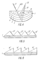
- FIG. 5 shows a light filter according to the invention with several prisms
- FIG. 6 shows a light filter according to the invention with several ioptical wedges
- FIG. 7 shows a light filter according to the invention with combinations of layers arranged one behind the other in the beam path;
- FIG. 8 shows a light filter according to the invention with spatially separated combinations of the layers
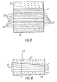
- FIG. 10 shows a light filter according to the invention with a stepless change in the wavelength of a filtered radiation
- FIG. 11 shows a light filter according to the invention with a device for compressing a layer structure
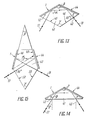
- FIG. 13 shows a light filter according to the invention with a substrate having the shape of a rhomboid in section
- FIG. 14 shows a light filter according to the invention with a substrate having the shape of an isosceles triangle in section;
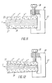
- FIG. 16 shows a light filter according to the invention with a body
- FIG. 17 shows a further embodiment of the light filter according to the invention with a body
- FIG. 18 shows a basic circuit diagram of an optical device according to the invention.
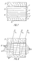
- the selective interference light filter has a layer structure 1 (FIG. 1) which contains equidistant layers 2, 3, 4 and 5 with a refractive index that changes periodically according to the depth. 1 schematically indicates how such a filter is manufactured.
- An element made of a transparent, light-sensitive material is taken, irradiated with a parallel luminous flux 6 by an optical system 7 from a light source 8.
- the element to be irradiated is arranged in front of a metal mirror 9, which is removed after the irradiation.
- the irradiation is carried out with at least one monochromatic radiation of a predetermined wavelength
- the wave of light flux 6 reflected by mirror 9 interferes with a striking wave, creating standing waves.
- the refractive index of the light-sensitive material changes differently.
- the element made of the light-sensitive material is given a layer structure 1.
- the wave bellies 10 correspond in that they come to lie equidistantly at a distance of ⁇ 0 / 2n from one another in the element to be irradiated, where n is the refractive index of the material the layer structure 1 the equidistant layers 2 to 5, which is why the periodicity of the layers 2 to 5 and consequently the layer thickness is.
- Levels 12 of maximum change in the refractive index of the light-sensitive material are indicated schematically by vertical lines.
- the number N of layers 2 to 5 in layer structure 1 depends on the thickness D of the element to be irradiated and the thickness d of each layer 2 to 5 and is determined by the relationship given.
- Each layer 2 to 5 is partially reflective for light radiation directed onto the layer structure.
- the interference of the beams reflected by the layers 2 to 5 has a maximum for a certain wavelength, which is the same as the path difference of the interference waves.
- the radiation of this wavelength is filtered off by the light filter under consideration.
- the element to be irradiated is made of a transparent, light-sensitive material, as which either a photo emulsion based on silver salts or bichromated gelatin, or photo-registering polymerizing agent, or a photopolymerizing composition is used.
- the layer structure 1 has a substrate, which is either a prism 13 (FIG. 2) or an optical one Wedge 14 (Fig. 3) is used, or the substrate is in the form of a lens I5 (Fig. 4).
- the layer structure 1 is applied to a reflecting surface 16, while the light radiation 17 is directed onto any free surface 18.
- the filtered radiation 19 emerges through another surface 20 of the prism 13.
- the layer structure 1 is applied to a surface 21 (FIG. 3) of the optical wedge 14, the light radiation 17 is directed onto its surface 22, and the filtered radiation 19 emerges through the same surface 22.
- the light filter When using the lens 15 (FIG. 4), the light filter has a construction similar to that described above and focuses the radiation 17 next to its filtering point and in the focal point 23 of the lens 15 if the light radiation 17 was collimated.
- the radiation 24 (FIGS. 2 to 4) reflected at the boundary between the surrounding medium and the light filter has a direction deviating from the filtered radiation 19 in all the embodiments considered.
- the substrate may contain more than one prism 13 or wedge 14 as shown in FIGS. 5 and 6.
- the prisms 13 '(or wedges 14') lie along the structure 1, and their number depends on the length of the structure 1.
- Each of the prisms 13 ' has dimensions and consequently a mass which are much smaller than in the embodiment according to FIG. 2 when a prism 13 is used.
- the mass and dimensions of all prisms 13 ' are smaller than the mass and dimensions of prism 13.
- the overall dimensions and the mass of the entire light filter according to FIG. 5 are therefore considerably smaller than in the embodiment according to FIG. 2, and it can be said that the construction of the entire light filter is quasi-flat.
- the design of the light filter is similar even when using a large number of wedges 14 '(Fig. 6).
- the element to be irradiated can be subjected to the action of two or more radiations with different wavelengths. Combinations of equidistant layers assigned to these wavelengths are formed in the element. The combinations of the layers in the layer structure are arranged in different ways, which are determined by the tasks and determination of the finished light filter,
- the combinations 25 and 26 of the layers 2 to 5 and 2 ', 3', 4 ', 5' lie one behind the other in the beam path of the radiation 17 (FIG. 2).
- the light filter has two substrates 27 (FIG. 7) and 28 made of glass.
- the combinations 29, 30 and 31 are spatially separated along the layer structure 1, which has individual sections, which is why the radiations 32, 33, 34 of the respective wavelengths ⁇ 1, ⁇ 2, ⁇ 3, which are filtered by all combinations 29 to 31, result as a result the radiation effect appeared on each section of structure 1, are separated in space.
- a light filter is schematically arranged, for the manufacture of which an element has been irradiated by radiation with a continuous spectrum.
- the layers 2 ′′, 3 ′′, 4 ′′, 5 ′′ lie in a layer structure 35 equidistant in a cross section through one of the layers 2 ′′ to 5 ′′ and the direction of a change in the thickness of the layers 2 "" to 5 "vertical plane 36.
- the thickness of the layers 2" to 5 “changes monotonically along the layer structure 35.
- Such a light filter allows a spectrum of radiation to be examined to be obtained or a stepless changeover of the Wavelength of the filtered radiation 17 (Fig. 1) by moving it in front of any aperture in a slit form (not shown in the drawing).
- a light filter has similar functional capabilities, in which a device 37 for compressing the same is arranged on the layer structure 1 (FIG. 11). It contains a screw clamp 38 and a screw 39 which changes the pressure force of the screw clamp 38.
- the layer structure 1 is made of an elastic compressible material, for example of bichromated gelatin.
- the layers 2 ′′ to 5 ′′ have an equidistance (FIG. 12) only in a cross section in analogy to this, as is shown in FIG. 10.
- the prism according to the invention can have an average shape of a rhomboid 40 (FIG. 13) or an isosceles triangle 41 (FIG. 14), which represents a special embodiment of the rhomboid and its properties are therefore not considered separately.
- Two layer structures 1 and 44 are applied to two symmetrical side surfaces 42 (FIG. 13), 43 of the rhomboid 40.
- the light radiation 17 is directed onto a free surface 45, while the filtered radiation 19, by being successively reflected by the layer structures 1 and 44, emerges through the other free surface 46.
- the angle ⁇ between the free surfaces 45 and 46 is based on the following relationships: selected, where ⁇ is the angle between the surfaces 42 and 43, on which the layer structures 1 and 44 are applied.
- prism 47 (FIG. 15) has a complicated shape with at least two pairs of side surfaces symmetrical in pairs 48, 49 or 50, 51 with a common plane of symmetry on: for a pair of surfaces 48, 49, layer structures 1, 4 are plotted, while the angles ⁇ and ⁇ between surfaces 48, 49 and 50, 51 of the pairs according to Relationship (3) can be selected.
- the light radiation 17 strikes the free surface 50 and is sequentially reflected by the structures 44 and 1, while the filtered radiation 19 emerges through the free surface 15.
- the light filter containing the layer structure 1 on the prism 13 has a body 52 in which an entry opening 53 for the passage of the radiation 17 and an opening 54 for the exit of the filtered radiation 19 are made.
- the inlet opening 53 forms a diaphragm, as which any light guide can appear, for example.
- the layer structure 1 is pivotable with respect to the radiation 17 supplied about the body 52 with the possibility of a simultaneous or separate longitudinal displacement.
- the prism 13 with the layer structure has a rotating mechanism which contains, for example, a worm drive 57, 58 and a handle 59.
- the prism 13 is attached to the gear 57 of the worm gear 57, 58.
- the prism is linearly displaced by means of a screw 60, which interacts with the toothed wheel 57, which is sprung by a spring 61.
- the radiation 17 is transmitted to the prism through a diaphragm formed by the openings 53, 55, 56 and, after being filtered off, emerges through the opening 54 on the opposite wall of the body 52.
- the body 52 ' (FIG. 17) can be arranged outside the light filter, and one wall thereof serves as the entry surface 16 of the prism 13.
- a diaphragm is arranged on the opposite wall 62 of the body 52', which is formed by a system of openings 53, 55 and 56 is formed in a sleeve 63.
- the longitudinal displacement device of the prism 13 contains a screw 64 and a spring 65 which cooperate with the sleeve 63 of the diaphragm and enable a mutual longitudinal displacement of the diaphragm and the prism 13 by changing the angle of incidence of the radiation 17 on the layer structure 1.
- the pivoting of the prism 13 fastened on a rotary bearing 66 is achieved by changing the shape of the body 52 ', as a corrugated tube is used.
- the filtered radiation 19 leaves the light filter through the surface 20.
- an optical device (FIG. 18) which contains the present light filter as a selecting element.
- the optical device contains a collimator lens 66, the mount 67 of which serves as an entry opening, a light filter 68 and a radiation receiver 69.
- the optical device of the given construction represents a gapless, bright monochromator.
- a radiation source 70 is introduced into the optical device, which is characterized by a continuous spectrum.
- the device serves as a monochromatic reflector with an adjustable wavelength.
- the selective interference light filter works as follows.
- Light radiation 17 is directed onto the light filter, and each layer 2 to 5 (FIG. 2) of the layer structure 1 reflects a small part of this radiation.
- a reflected radiation 19 is formed which contains many light beams which have a constant path difference from one another which depends on the layer thickness d, the refractive index n and the angle ⁇ of the incidence of light on the layer structure 1. The result of the interference amounts to the fact that the interference maximum is only reached for the wavelength ⁇ that the condition enough.
- the light-sensitive material of the element to be irradiated is chosen to be practically transparent for the target wavelength ⁇ o , which at the same time changes its refractive index slightly under the effect of light and has sufficient resolution for the formation of a layer structure (the internal inhomogeneities in the material should be less than ⁇ / 15) .
- the radiation 21 reflected at the air-light filter boundary is linearly separated from the radiation 19 reflected by the layers 2 to 5 or even propagates in another direction. Therefore, it does not interfere with the radiation 19 and does not distort the interference image.
- the separation of the radiation 24 reflected at the air / light filter boundary is angular, and the changeover range for the wavelength is wider than in the case of a plane-parallel substrate.
- the lens 15 (FIG. 4) in the reflected radiation 19, the maximum is observed for one wavelength, the monochromatic light being focused at the focal point 23 of the lens 15 when the filter is incident on a plane-parallel light beam.
- the light filter with the combinations 25 and 26, 29, 30 and 31 reflects two or more wavelengths upon the incidence of the radiation 17 characterized by a continuous spectrum, whereby the waves in the room can be covered or separated (29 ', 30' and 31 'or 29, 30, 31).
- the wavelength ⁇ of the reflected light changes.
- the possibility of changing the wavelength of the reflection light by changing the angle of light incidence on the filter is retained.
- the construction of the light filter shown in Figs. 11, 12 enables the value d ⁇ / dx, i.e. to change the dispersion of the light filter.
- the light filter according to FIGS. 13, 14 reflects only one wavelength and only in the case when the wave of this length falls on the light filter at a certain angle (The parameters of the prism are chosen such that radiation incident on the light filter normal to the entrance surface 31 is separated).
- the light filter which is designed in the manner as shown in FIGS. 15, 16, 17, only separates a light that is normally incident thereon, because, for example, the diaphragm (FIGS. 16, 17) does not transmit rays that are incident at an oblique angle, and with a certain mutual orientation of the diaphragm and the layer structure 1, the light filter filters out the light of only one wavelength.
- the light filter is set to any wavelength from a desired range.
- an angular scan is carried out, i.e. the direction of the light source is determined with a desired wavelength (not shown in the drawings).
- the optical device which contains the light filter under consideration as a selecting element, a collimator element and a radiation receiver, can also be used as gapless bright monochromator work, with the help of which the spectrum of any, including weak, radiation sources is analyzed.
- the light from the source strikes the lens, while the light filter 1 reflects the selected wavelength and directs it to the radiation receiver. By swiveling the light filter, the wavelength is changed.
- the device is used to irradiate various objects.
- the light from the source with the continuous spectrum is incident on the collimator lens and is filtered by the light filter.
- a monochromatic radiation is generated at the exit which irradiates the object.
- the selective interference light filter has a layer structure which is produced from a photo emulsion which contains a silver bromide.
- the thickness of the layer structure is 18 ⁇ m. This contains at least 85 layers.
- the refractive index varies from 1.52 to 1.60.
- the filtered radiation has the wavelength ⁇ in a range from 480 to 633 nm.
- the reflection factor amounts to up to 40% in the green spectral range.
- the spectral bandwidth makes up 8 to 10 nm in the entire changeover range for the wavelength.
- the selective interference light filter contains a layer structure made of brominated gelatin (with ammonium dichromate) is made.
- the thickness of the layer structure is 10 ⁇ m. This contains at least 60 layers.
- the refractive index varies from 1.50 to 1.60.
- the filtered radiation has the wavelength ⁇ in a range from 380 to 488 nm.
- the reflection factor is up to 70% in the blue-green spectral range.
- the spectral bandwidth is between 5 and 6 nm.
- the selective interference light filter contains a layer structure made of photo-registering polymerizing agent of the type of a registering oxidant with anthracene.
- the thickness of the layer structure is 1 nm. This contains at least 4500 layers.
- the filtered radiation has the wavelength ⁇ in a range from 475 to 633 nm.
- the reflection factor is up to 10% in the green spectral range.
- the spectral bandwidth is 0.1 to 0.2 nm.
- the selective interference light region contains a layer structure which is produced from a liquid polymerizing composition.
- the composition has a radically polymerizing vinyl monomer and a stabilizing agent.
- the thickness of the layer structure is 20 ⁇ m.
- the filtered radiation has a wavelength of 350 to 442 nm.
- the reflection factor is 15%, the spectral bandwidth 3 to 4 nm.
- the selective interference light filter contains a layer structure made of a silver bromide Photo emulsion is made.
- the thickness of the layer structure is 21 ⁇ m. This contains at least 100 layers.
- the layer structure lies on the hypotenuse surface of a three-sided prism, which has angles of 90 °, 45 °, 45 °.
- the filtered radiation has a wavelength in a range from 360 to 610 nm.
- the reflection range is from 40% in the red and violet spectral range to 70% in the green spectral range.
- the spectral bandwidth is 8 to 10 nm.
- the selective interference light filter contains a layer structure which is produced from a photo emulsion comprising silver bromide.
- the thickness of the layer structure is 21 ⁇ m. This contains at least 100 layers.
- the layer structure is applied to a surface of an optical wedge at an angle of 30 °.
- the filtered radiation has a wavelength in a range from 570 to 633 nm.
- the reflection factor is about 60%.
- the selective interference light filter contains a layer structure which is produced from a photo emulsion comprising silver bromide.
- the thickness of the layer structure is 21 ⁇ m.
- the layer structure is applied to a flat substrate.
- the filtered radiation has two wavelengths, which are in a bundle side by side reproduce. If a screen is set up in the radiation path of the filtered radiation, the spot on the screen consists of two parts of different colors. When the angle of incidence of the light radiation on the filter is changed from 0 to 35 °, the two lengths change, the shorter one changing from 380 to 488 nm and the longer one from 570 to 633 nm.
- the selective interference light filter contains a layer structure which is produced from a photo emulsion comprising silver bromide.
- the thickness of the layer structure is 42 ⁇ m.
- the layers produced by the first laser take up half the thickness of the plate, the other half thickness is occupied by the layers produced by the second laser.
- the first combination of the layers lies first in the radiation path of the radiation incident on the filter. Analysis of the filtered radiation shows that it contains two wavelengths at the same angle of incidence on the filter. When the angle of incidence changes, the wavelengths of the filtered radiation change from 570 to 633 and from 350 to 488 nm for ⁇ ' O or ⁇ " O .
- the selective interference light filter contains a layer structure which is produced from a photo emulsion comprising silver bromide.
- the filter is irradiated by a source characterized by a continuous spectrum, it becomes a radiation with a wavelength of 449 nm and with a spectral bandwidth of 10 nm, but only with a normal one Incidence of radiation filtered on the filter.
- the angle of incidence changes by 1 °
- the intensity of the filtered radiation drops twice, while when the angle of incidence changes by 2 °, the filter practically does not let light radiation through.
- the light filter according to the invention is selective, narrow-band, switchable according to the wavelength. It can be easier to manufacture and multifunctional to use.
- the switchable light filter which has a switchover range of 240 nm with a spectral bandwidth of 8 nm, can replace 30 switchable light filters with the same spectral band. Considering the cost of a light filter, the application of the invention has a noticeable economic effect.
- the invention can be used in spectroscopy, lighting technology, in optical and laser device construction, in carrying out space research.
Landscapes
- Physics & Mathematics (AREA)
- General Physics & Mathematics (AREA)
- Optics & Photonics (AREA)
- Exposure And Positioning Against Photoresist Photosensitive Materials (AREA)
- Optical Filters (AREA)
- Optical Modulation, Optical Deflection, Nonlinear Optics, Optical Demodulation, Optical Logic Elements (AREA)
Abstract
Description
Die Erfindung bezieht sich auf optische Geräte und betrifft insbesondere selektive Interferenzlichtfilter und optische Geräte unter Benutzung derselben. Die Erfindung kann in der Spektroskopie, Lichttechnik, im optischen und Lasergerätebau, bei der Durchführung von Weltraumforschungen verwendet werden.The invention relates to optical devices, and more particularly relates to selective interference light filters and optical devices using the same. The invention can be used in spectroscopy, lighting technology, in optical and laser device construction, in carrying out space research.
Es sind Interferenzlichtfilter bekannt, die zwei oder mehrere Gruppen einander abwechselnder Schichten aus Isolierstoff mit unterschiedlichem Brechungsindex enthalten, die eine optische Dicke aufweisen, die eine Viertelwellenlänge eines auf ein Lichtfilter gerichteten Lichtstroms (SU, A, 539284; SU, A, 881647) beträgt.Interference light filters are known which contain two or more groups of alternating layers of insulating material with different refractive index, which have an optical thickness which is a quarter wavelength of a luminous flux directed onto a light filter (SU, A, 539284; SU, A, 881647).
Derartige Filter sind kompliziert in der Herstellung, auf sie werden unbedingt Schutzüberzüge aufgetragen, die, indem sie den Prozess der Herstellung der Lichtfilter zusätzlich erschwierigen, auch die optischen Eigenschaften des Lichtfilters, d.h. die Strahlungsdurchlässigkeit, verschlechtern.Such filters are complicated to manufacture, protective coatings are necessarily applied to them, which, by additionally complicating the process of manufacturing the light filters, also the optical properties of the light filter, i.e. the radiation permeability, deteriorate.
Für die Herstellung derartiger Lichtfilter können ausserdem Werkstoffe erhähter chemischer Reinheit notwendig werden.Materials of increased chemical purity may also be necessary for the production of such light filters.
In den bekannten Lichtfiltern ist eine stufenlose Umstellung der Wellenlänge in sehr engen Grenzen möglich.In the known light filters, the wavelength can be changed continuously within very narrow limits.
Es sind selektive Interferenzfilter bekannt, die eine Schichtstruktur aufweisen, von deren jeder Schicht eine auf das Lichtfilter gerichtete Lichtstrahlung reflektiert wird. Die Schichtstruktur wird aus einer auf eine Metallunterlage aufgebrachten Dielektrikumschicht, die eine durch π teilbare Halbwertsbreite einer Phase aufweist, und einer geraden Anzahl von einander abwechselnden Viertelwellenschichten aus zwei Dielektrika mit einem hohen bzw. niedrigen Brechungsindex gebildet. Diese Schichtkombination ist von oben mit einer metallen Absorptionsschicht abgedeckt, die eine Dicke besitzt, die viel dünner als die Arbeitswellenlänge ist. ("Optika i spektroskopia /Optik und Spektroskopie/", Bd. 40, 1976, Verlag "Nauka", Leningrad, N.D.Goldina, Ju.V.Troitsky "Uzkopolosnye filtry v otrazhonnom svete /Schmalbandfilter im reflektierten Licht/", S. 935 bis 938).Selective interference filters are known which have a layer structure, from each layer of which a light radiation directed onto the light filter is reflected. The layer structure is formed from a dielectric layer applied to a metal base, which has a half-width that can be divided by π of a phase, and an even number of alternating quarter-wave layers from two dielectrics with a high or low refractive index. This combination of layers is from above covered with a metal absorption layer that has a thickness much thinner than the working wavelength. ("Optika i spektoskopia / Optik und Spektoskopie /", vol. 40, 1976, publisher "Nauka", Leningrad, NDGoldina, Ju.V. Troitsky "Uzkopolosnye filtry v otrazhonnom svete / narrow band filter in reflected light /", p. 935 bis 938).
Derartiges bekanntes Lichtfilter reflektiert ausser den selektiven Wellenlängen, die über die Grenzen des Reflexionsbandes hinausgehen und Störungen darstellen. Darüber hinaus weisen diese Lichtfilter Nachteile auf, die den vorstehend dargelegten gleich sind.Such known light filter reflects not only the selective wavelengths that go beyond the limits of the reflection band and represent interference. In addition, these light filters have disadvantages that are the same as those set out above.
Es sind optische Geräte, nämlich Spektralgeräte (I.V.Peisakhson "Optika spektralnykh priborov /Optik der Spektralgeräte/", 1975, Verlag "Mashinostroenie", Leningrad, S. 5 bis 10), bekannt, die einen Eintritts- und einen Austrittsspalt, ein Kollimator- und ein Kammerobjektiv, ein selektierendes, beispielsweise ein dispergierendes System, das auf der Basis eines dispergierenden Primas oder eines Beugungsgitters hergestellt ist, und eine Empfangseinrichtung enthalten. Derartige Spektralgeräte gestatten es, die Arbeitswellenlänge stufenlos zu ändern, das Vorhandensein eines schmalen Eintrittsspaltes begrenzt aber die Lichtstärke dieser Geräte im Hinblick auf den Lichtstrom, weshalb sich nur eine intensive Strahlung untersuchen lässt.Optical devices, namely spectral devices (IVPeisakhson "Optika spektralnykh priborov / Optik der spectralgeräte /", 1975, publisher "Mashinostroenie", Leningrad, pp. 5 to 10), are known which have an entrance and an exit slit, a collimator and a chamber objective, a selective, for example a dispersing system, which is made on the basis of a dispersing primate or a diffraction grating, and contain a receiving device. Such spectral devices allow the working wavelength to be changed continuously, but the presence of a narrow entrance slit limits the light intensity of these devices with regard to the luminous flux, which is why only intensive radiation can be examined.
Es sind ferner optische Geräte bekannt, die eine Quelle kontinuierlicher Strahlung, ein oder zwei selektierende Elemente, eine Halterung oder eine Küvette für das zu bestrahlende Objekt enthalten. Diese Geräte können Objektive und einen Strahlungsempfänger enthalten. In diesen Geräten dienen als selektierendes Element entweder ein Prisma oder ein Beugungsgitter oder Lichtfilter (V.V.Lebedeva "Tekhnika opticheskoi spektroskopii /Technik der optischen Spektroskopie/", 1977, Verlag der Moskauer Universität, Moskau, S. 166).Optical devices are also known which contain a source of continuous radiation, one or two selecting elements, a holder or a cuvette for the object to be irradiated. These devices can include lenses and a radiation receiver. In these devices, either a prism or a diffraction grating or light filter serve as the selecting element (V.V. Leebedeva "Tekhnika opticheskoi spektoskopii / Technik der Optik Spektoskopie /", 1977, Verlag der Moscow University, Moscow, p. 166).
Die Anwendung des Prismas und des Beugungsgitters erfordert die Einführung eines die Lichtstärke begrenzenden Spaltes. Werden als selektierendes Element Lichtfilter eingesetzt, so erfolgt die Selektion der Wellenlängen diskret, wozu Sätze von nach den Wellenlängen nicht umstellbaren Lichtfiltern angewendet werden. Die Anwendung eines nach den Wellenlängen umstellbaren Keil-Lichtfilters macht auch die Einführung eines die Lichtstärke beschränkenden Spaltes notwendig. Ausserdem wird das Keil-Interferenzlichtfilter durch eine keilförmige Aufdampfung von Schichten reiner Werkstoffe in Wakuum gefertigt. Diese Technologie ist sehr kompliziert, weshalb die Geräte mit den Keilfiltern keine weite Anwendung finden. Die Erfindung bezweckt die Schaffung eines selektiven schmalbandigen, nach den Wellenlängen umstellbaren Interferenzlichtfilters, das eine einfachere Fertigungstechnologie aufweist und multifunktional ist.The application of the prism and the diffraction grating requires the introduction of a gap limiting the light intensity. If light filters are used as the selection element, the wavelengths are selected discretely, for which purpose sets of light filters that cannot be changed according to the wavelengths are used. The use of a wedge light filter that can be changed according to the wavelengths also necessitates the introduction of a slit that limits the light intensity. In addition, the wedge interference light filter is manufactured by wedge-shaped evaporation of layers of pure materials in a vacuum. This technology is very complicated, which is why the devices with the wedge filters are not widely used. The invention aims to create a selective narrow-band interference light filter which can be changed according to the wavelength, which has a simpler production technology and is multifunctional.
Der Erfindung liegt die Aufgabe zugrunde, ein selektives Interferenzlichtfilter und ein optisches Gerät unter Benutzung desselben zu schaffen, die es gestatten, die Arbeitswellenlänge bei Änderung des Einfallswinkels einer Lichtstrahlung durch Änderung des Gangunterschiedes von Interferenzstrahlen in weiten Grenzen stufenlos umzustellen.The invention has for its object to provide a selective interference light filter and an optical device using the same, which allow to change the working wavelength when changing the angle of incidence of light radiation by changing the path difference of interference beams within wide limits.
Die gestellte Aufgabe wird dadurch gelöst, das in dem selektiven Interferenzlichtfilter, das eine Schichtstruktur aufweist, deren jede Schicht für eine auf das Lichtfilter gerichtete Strahlung reflektierend ist, gemäss der Erfindung die Schichten der Schichtstruktur äquidistant mit einem sich nach der Tiefe periodisch ändernden Brechungsindex ausgeführt und durch Bestrahlung eines vor einem Spiegel erst im Vorgang der Bestrahlung angeordneten Elementes aus einem für die Strahlung durchlässigten lichtempfindlichen Werkstoff mit mindestens einer monochromatischen Strahlung vorgegebener Wellenlänge gebildet sind.The object is achieved in that in the selective interference light filter, which has a layer structure, each layer of which is reflective for radiation directed onto the light filter, the layers of the layer structure are carried out equidistantly with a periodically changing refractive index according to the invention, and by irradiating an element arranged in front of a mirror only in the process of irradiation and made of a light-sensitive material that is transparent to the radiation with at least one monochromatic radiation of a predetermined wavelength are formed.
Im Vergleich zu den durch Vakuumbedampfung von planparallelen Schichten reiner Werkstoffe erzeugten Interferenzlichtfiltern zeichnen sich die erfindungsgemässen Lichtfilter durch die Möglichkeit einer stufenlosen Umstellung der Arbeitswellenlänge in recht weiten Grenzen aus.In comparison to the interference light filters produced by vacuum vapor deposition of plane-parallel layers of pure materials, the light filters according to the invention are distinguished by the possibility of a continuous change in the working wavelength within very wide limits.
Die Schichtstruktur reflektiert verschiedene Wellenlängen in Abhängigkeit vom Winkel des Lichteinfalls auf diese Struktur.The layer structure reflects different wavelengths depending on the angle of incidence of light on this structure.
Der Umstellbereich der Länge einer von einer Schichtstruktur rückgestrahlten Welle hängt von einem effektiven Brechungsindex dieser Struktur ab, und je grösser der Brechungsindex ist, desto schmäler ist der Umstellbereich. Zur selben Zeit ist der Brechungsindex um so grösser und die Spektralbande um so schmäler, je grösser die Schichtzahl der Struktur und je grösser die Differenz der Brechungsindexe der Schichten ist.The changeover range of the length of a wave retroreflected by a layer structure depends on an effective refractive index of this structure, and the larger the refractive index, the narrower the changeover range. At the same time, the larger the number of layers of the structure and the greater the difference in the indices of refraction of the layers, the greater the refractive index and the narrower the spectral band.
Das zu bestrahlende Element kann entweder aus einer Fotoemulsion auf der Basis von Silbersalzen oder aus bichromierter Gelatine, oder aus fotoregistrierendem Polymerisationsmittel, oder aus fotopolymerisierender Stoffkomposition hergestellt werden.The element to be irradiated can either be produced from a photo emulsion based on silver salts or from bichromated gelatin, or from photo-registering polymerizing agent, or from photopolymerizing composition.
Durch die Vakuumbedampfung werden in der Regel höchstens 30 bis 40 Schichten erzeugt. Die weitere Vergrösserung der Schichtzahl führt zu einer Speicherung von Defekten, weshalb sie keine Vergrösserung des Reflexionsfaktors und keine Einengung der Spektralbande bewirkt. Um bei einer geringen Schichtzahl einen grossen Reflexionsfaktor und eine schmale Schpektralbande zu haben, muss man Werkstoffe mit einer grossen Differenz von Brechungsindexen n₁ und n₂ nehmen. Da n₁ unter 1,3 nicht liegen darf, nimmt man n₂ in der Regel grösser als 2. Im Ergebnis erweist sich der effektive Brechungsindex eines Schichtsystems als in der Nähe von 2 oder darüber liegend.Vacuum evaporation generally produces a maximum of 30 to 40 layers. The further increase in the number of layers leads to the storage of defects, which is why it does not increase the reflection factor and does not narrow the spectral band. In order to have a large reflection factor and a narrow spectral band with a small number of layers, one must take materials with a large difference in
Das Verfahren zur Herstellung der erfindungsgemässen Lichtfilter gestattet es, Lichtfilter mit einer grossen Schichtzahl (von ca. 100 bis 200) bei einer automatisch einzuhaltenden Genauigkeit von sich ergebenden Schichtdicken (halbe Wellenlänge) zu fertigen. Der effektive Brechungsindex des Schichtsystems bleibt nahe am Brechungsindex des lichtempfindlichen Ausgangsstoffes liegen. (Für eine Fotoemulsion aus Silbersalzen beträgt er ca. 1,5). Die grosse Schichtzahl sichert bei einem niedrigen Aussteuerungsgrad des Brechungsindexes einen hohen Reflexionsfaktor und eine schmale Spektralbande (nicht schlechter als bei den durch Bedampfung erzeugten Filtern), während der niedrige effektive Brechungsindex einen weiten Umstellbereich für die Wellenlänge gewährleistet.The method for producing the light filter according to the invention allows light filters with a large number of layers (from approximately 100 to 200) to be used automatically the accuracy to be observed of the resulting layer thicknesses (half wavelength). The effective refractive index of the layer system remains close to the refractive index of the light-sensitive raw material. (For a photo emulsion made of silver salts, it is approximately 1.5). The large number of layers ensures a high reflection factor and a narrow spectral band (not worse than in the case of filters produced by vapor deposition) with a low degree of modulation of the refractive index, while the low effective refractive index ensures a wide changeover range for the wavelength.
Es ist zweckmässig, dass das Lichtfilter ein Substrat aufweist, auf welches eine Schichtstruktur aufgebracht ist. Das Lichtfilter, welches ein Substrat aufweist, auf das eine Schichtstruktur aufgetragen ist, besitzt gegenüber einem Lichtfilter ohne Substrat folgende Vorteile: grosse Festigkeit aufgrund der Festigkeit des Substrats, höheren Reflexionsfaktor, schmälere Spektralbande und bessere Kontrast wegen der Entfernung eines Strahls aus der Interferenz, der an der Grenze Luft - Schichtstruktur reflektiert wird. In Abhängigkeit vom Stoff des Substrats und dem Arbeitswellenbereich kann das Substrat zur Unterdrückung von Interferenzmaxima höherer Ordnungen gegenüber der ersten Arbeitsordnung dienen.It is expedient for the light filter to have a substrate to which a layer structure is applied. The light filter, which has a substrate on which a layer structure is applied, has the following advantages over a light filter without a substrate: high strength due to the strength of the substrate, higher reflection factor, narrower spectral band and better contrast because of the removal of a beam from the interference is reflected at the air - layer structure boundary. Depending on the material of the substrate and the working wave range, the substrate can serve to suppress interference maxima of higher orders compared to the first working order.
Als Substrat kann mindestens ein Prisma, auf dessen Reflexionsfläche eine Schichtstruktur aufliegen kann, während die Lichtstrahlung auf eine beliebige freie Prismenfläche gerichtet werden kann, oder mindestens ein optischer Keil, auf dessen eine Fläche eine Schichtstruktur aufgebracht werden kann, während die Lichtstrahlung auf dessen andere Fläche gerichtet werden kann, oder ein Linsenform aufweisendes Element dienen.At least one prism, on the reflection surface of which a layer structure can rest, while the light radiation can be directed onto any free prism surface, or at least one optical wedge, on the one surface of which a layer structure can be applied, while the light radiation on the other surface, can be used as the substrate can be directed, or serve a lens-shaped element.
Das Lichtfilter mit einem prismenförmigen Substrat erweitert den Umstellbereich für die Arbeitswellenlängen.The light filter with a prism-shaped substrate extends the switching range for the working wavelengths.
Das Lichtfilter, in welchem der optische Keil als Substrat auftritt, hat gegenüber einem Lichtfilter mit einem flachen Substrat den Vorteil, das der an der Grenze Luft - Substrat reflektierte Strahl von den Interferenzstrahlen nicht nur linear abgetrennt ist, sondern auch eine andere Richtung aufweist, wie dies auch beim prismenförmigen Substrat der Fall ist. Zur selben Zeit bleibt im Lichtfilter mit dem Keil der Vorteil des Lichtfilters mit dem flachen Substrat beibehalten - es besitzt kleinere Abmessungen, während seine Eintritts- und Austrittsfläche zusammenfallen.The light filter in which the optical wedge appears as a substrate has the advantage over a light filter with a flat substrate that the beam reflected at the air - substrate boundary is not only linearly separated from the interference beams, but also has a different direction, such as this is also the case with the prismatic substrate. At the same time, the advantage of the light filter with the flat substrate is retained in the light filter with the wedge - it has smaller dimensions, while its entrance and exit surfaces coincide.
Das Lichtfilter mit dem linsenförmigen Substrat stellt nicht nur ein filterndes, sondern auch ein fokussierendes optisches Element dar.The light filter with the lenticular substrate is not only a filtering, but also a focusing optical element.
Bei der Bestrahlung eines Elements aus lichtempfindlichem Material durch zwei oder mehrere monochromatische Strahlungen mit verschiedenen Wellenlängen kann die Schichtstruktur jeweils zwei oder mehrere Kombinationen äquidistanter Schichten aufweisen, deren jede einer eigenen Wellenlänge der monochromatischen, Strahlung zugeordnet ist.When an element made of light-sensitive material is irradiated by two or more monochromatic radiations with different wavelengths, the layer structure can each have two or more combinations of equidistant layers, each of which is assigned to a separate wavelength of the monochromatic radiation.
Derartiges Lichtfilter ist polychrom. Es reflektiert zwei oder mehr Wellenlängen zugleich, deren jede bei Änderung des Winkels des Einfalls der Strahlung auf das Lichtfilter umgestellt wird.Such a light filter is polychrome. It reflects two or more wavelengths at the same time, each of which is switched to the light filter when the angle of incidence of the radiation changes.
Zweckmässig ist, dass in der Schichtstruktur die Kombinationen der äquidistanten Schichten im Strahlengang der auf die Schichtstruktur gerichteten Lichtstrahlung hintereinander angeordnet sowie räumlich zur Deckung gebracht sind.It is expedient that the combinations of the equidistant layers are arranged one behind the other in the layer structure in the beam path of the light radiation directed onto the layer structure and are spatially coincident.
Derartiges Lichtfilter wird viel einfacher als ein ähnliches bekanntes Lichtfilter hergestellt. Der räumliche Zusammenfall der Kombinationen der äquidistanten Schichten gestattet es, bei der Reflexion das Verhältnis der vorgegebenen Wellenlängen mit einer hohen Genauigkeit zu erhalten, denn die verschiedenen Kombinationen der Schichten werden gleichzeitig (zum selben Zeit-moment) erhalten.Such a light filter is manufactured much more easily than a similar known light filter. The spatial coincidence of the combinations of the equidistant layers makes it possible to obtain the ratio of the predetermined wavelengths with a high degree of accuracy during reflection, because the different combinations of the layers are simultaneously (at the same time) receive.
Es erwies sich auch als zweckmässig, dass zwei oder mehr Kombinationen der äquidistanten Schichten durch Parallelbündel der monochromatischen Strahlung gebildet sind, wobei die Schichtstruktur Einzelabschnitte enthält, die Kombinationen der äquidistanten Schichten darstellen, die Einzelabschnitten der Wellenfront der auf die Schichtstruktur gerichteten Lichtstrahlung entsprechen.It also proved to be expedient for two or more combinations of the equidistant layers to be formed by parallel bundles of the monochromatic radiation, the layer structure containing individual sections which represent combinations of the equidistant layers which correspond to individual sections of the wavefront of the light radiation directed onto the layer structure.
Derartiges Lichtfilter liefert bei der Reflexion räumlich auseinandergebrachte Strahlen unterschiedlicher Wellenlängen.Such a light filter delivers spatially separated beams of different wavelengths during reflection.
Es erwies sich als vorteilhaft, dass die Schichtstruktur Schichten aufweist, deren Aquidistanz im Querschnitt der Schichtstruktur durch eine Ebene erfüllt wird, die gleichzeitig zu einer beliebigen Schicht und zu der Richtung der Änderung der Schichtdicke perpendikular ist, und durch eine Strahlung gebildet ist, die durch ein kontinuierliches Spektrum gekennzeichnet wird.It has proven to be advantageous that the layer structure has layers whose aquidistance in the cross section of the layer structure is fulfilled by a plane which is simultaneously perpendicular to any layer and to the direction of the change in layer thickness, and is formed by radiation which is formed by a continuous spectrum is characterized.
Derartiges Lichtfilter erlaubt es, die Wellenlänge nicht nur durch Änderung des Winkels des Lichteinfalls auf das Lichtfilter, sondern auch durch Längsverschiebung des Lichtfilters in der Nähe einer Spaltblende umzustellen. Gegenüber dem bekannten Keil-Zichtfilter, das durch eine keilförmige Vakuumbedampfung von Stoffschichten erzeugt ist, wird das vorliegende Lichtfilter durch eine sehr einfache Fertigungstechnologie gekennzeichnet.Such a light filter allows the wavelength to be changed not only by changing the angle of the incidence of light onto the light filter, but also by longitudinally displacing the light filter in the vicinity of a slit diaphragm. Compared to the known wedge-type filter, which is produced by wedge-shaped vacuum vapor deposition of layers of material, the present light filter is characterized by a very simple manufacturing technology.
Auf der Schichtstruktur kann eine Einrichtung für deren Zusammendrücken angeordnet werden, die für eine lineare Änderung der Dicke der äquidistanten Schichten längs der Schichtstruktur sorgt.A device for compressing them can be arranged on the layer structure, which ensures a linear change in the thickness of the equidistant layers along the layer structure.
Deshalb wird in der Fertigungstechnologie für das Lichtfilter die Änderung des Brechungsindexes mit sehr einfachen Mitteln erreicht.Therefore, in the manufacturing technology for the light filter, the change in the refractive index is achieved with very simple means.
Das Prisma kann im Schicht die Form eines Rhomboids aufweisen, auf dessen zwei symmetrische Seitenflächen gleiche Schichtstrukturen aufgebracht sind.The prism can have the shape of a rhomboid in the layer have, on the two symmetrical side surfaces the same layer structures are applied.
Das Prisma kann auch zwei Paare zueinander symmetrischer Seitenflächen mit einer gemeinsamen Symmetrieebene aufweisen, und auf jeder Seitenfläche eines Paares können die Schichtstrukturen aufliegen.The prism can also have two pairs of mutually symmetrical side surfaces with a common plane of symmetry, and the layer structures can rest on each side surface of a pair.
Derartiges Lichtfilter ist selektiv sowohl nach der Wellenlänge als auch nach dem Einfallswinkel. Es reflektiert die Lichtstrahlung nur einer Wellenlänge, die sich in einer bestimmten Richtung ausbreitet, und kann ausserdem kleinere Abmessungen und Masse durch Entfernung nichtfunktionierender Teile des Rhomboids aufweisen.Such a light filter is selective both according to the wavelength and the angle of incidence. It reflects the light radiation of only one wavelength, which propagates in a certain direction, and can also have smaller dimensions and mass due to the removal of non-functioning parts of the rhomboid.
Für die genaue Einstellung der abgefilterten Wellenlänge und für die Kontrolle des Winkels des Lichteinfalls auf die Schichtstruktur erwies es sich als vorteilhaft, dass das Lichtfilter einen Körper aufweist, in dessen Wänden zwei Öffnungen für den Strahlendurchgang zur Schichtstruktur bzw. für den Austritt der abgefilterten Strahlung ausgeführt sind.For the exact setting of the filtered wavelength and for the control of the angle of the incidence of light on the layer structure, it has proven to be advantageous that the light filter has a body, in the walls of which two openings are made for the radiation passage to the layer structure or for the exit of the filtered radiation are.
Die Schichtstruktur kann im Körper schwenkbar und/oder linear verschiebbar in bezug auf die geführten Strahlung angeordnet sein.The layer structure can be arranged in the body so as to be pivotable and / or linearly displaceable with respect to the guided radiation.
In diesem Fall ist die austretende abgefilterte Strahlung durch die Öffnung im Körper nicht begrenzt, was bei denjenigen Konstruktionen des Lichtfilters von Bedeutung sein kann, wo sich die abgefilterte Strahlung im Raum verschiebt.In this case, the emitted filtered radiation is not limited by the opening in the body, which can be important in those constructions of the light filter where the filtered radiation shifts in space.
Das Lichtfilter kann auch einen Körper aufweisen, als dessen eine Wand die Eintrittsfläche des Prismas oder des optischen Keiles dienen wird, während an der gegenüberliegenden Körperwand eine Blende für den Strahlendurchgang zur Schichtstruktur angebracht werden kann, wobei die Schichtstruktur und die Blende mit Möglichkeit einer gegenseitigen Schwenkung und/oder einer linearen Verschiebung ausgeführt werden können.The light filter can also have a body, one wall of which the entry surface of the prism or the optical wedge will serve, while an aperture for the beam passage to the layer structure can be attached to the opposite body wall, the layer structure and the aperture with the possibility of mutual pivoting and / or a linear displacement can be carried out.
In derartigen Lichtfiltern kann die Strahlenrichtung und/oder die Länge der reflektierten Welle abgetastet werden.The beam direction and / or the length of the reflected wave can be scanned in such light filters.
Die Aufgabe wird auch dadurch gelöst, dass in einem optischen Gerät, das ein selektierendes Element zur Abtrennung einer oder mehrerer Wellenlängen von einer darauf einfallenden Strahlung enthält, gemäss der Erfindung als selektierendes Element das vorliegende selektive Interferenzlichtfilter eingesetzt ist, das um eine auf dieses gerichtete Lichtstrahlung schwenkbar angeordnet ist.The object is also achieved in that, in accordance with the invention, the present selective interference light filter is used as an selecting element in an optical device which contains a selecting element for separating one or more wavelengths from radiation incident thereon is pivotally arranged.
Dieses Gerät weist eine grössere Lichtstärke gegenüber den bekannten auf.This device has a greater light intensity than the known ones.
Das erfindungsgemässe Lichtfilter sichert eine stufenlose Änderung der Arbeitswellenlänge, hat eine schmale Spektralbande, einen hohen Kontrast und Reflexionsfaktor.The light filter according to the invention ensures a continuous change in the working wavelength, has a narrow spectral band, a high contrast and reflection factor.
Die Erfindung soll durch die nachstehende Beschreibung von Ausführungsformen anhand der beiliegenden Zeichnungen näher erläutert werden. Es zeigt:The invention will be explained in more detail by the following description of embodiments with reference to the accompanying drawings. It shows:
Fig. 1 ein erfindungsgemässes selektives Interferenzlichtfilter;1 shows a selective interference light filter according to the invention;
Fig. 2 dto. mit einem prismenförmigen Substrat erfindungsgemäss;2 dto. With a prismatic substrate according to the invention;
Fig. 3 dto. mit einem Substrat in Form eines optischen Keiles gemäss der Erfindung;3 dto. With a substrate in the form of an optical wedge according to the invention;
Fig. 4 dto. mit einem linsenförmigen Substrat gemäss der Erfindung;4 dto. With a lenticular substrate according to the invention;
Fig. 5 ein erfindungsgemässes Lichtfilter mit mehreren Prismen;5 shows a light filter according to the invention with several prisms;
Fig. 6 ein erfindungsgemässes Lichtfilter mit mehreren ioptischen Keilen;6 shows a light filter according to the invention with several ioptical wedges;
Fig. 7 ein erfindungsgemässes Lichtfilter mit Kombinationen von im Strahlengang hintereinander angeordneten Schichten;7 shows a light filter according to the invention with combinations of layers arranged one behind the other in the beam path;
Fig. 8 ein erfindungsgemässes Lichtfilter mit räumlich auseinandergebrachten Kombinationen der Schichten;8 shows a light filter according to the invention with spatially separated combinations of the layers;
Fig. 9 ein erfindungsgemässes Lichtfilter mit räumlich zur Deckung gebrachten Kombinationen der Schichten;9 shows a light filter according to the invention with combinations of the layers spatially overlapped;
Fig. 10 ein erfindungsgemässes Lichtfilter mit einer stufenlosen Umstellung der Wellenlänge einer abgefilterten Strahlung;10 shows a light filter according to the invention with a stepless change in the wavelength of a filtered radiation;
Fig. 11 ein erfindungsgemässes Lichtfilter mit einer Einrichtung für ein Zusammendrücken einer Schichtstruktur;11 shows a light filter according to the invention with a device for compressing a layer structure;
Fig. 12 dto, mit zusammengedrückten Schichten erfindungsgemäss;12 dto, with compressed layers according to the invention;
Fig. 13 ein erfindungsgemässes Lichtfilter mit einem im Schnitt die Form eines Rhomboids aufweisenden Substrat;13 shows a light filter according to the invention with a substrate having the shape of a rhomboid in section;
Fig. 14 ein erfindungsgemässes Lichtfilter mit einem im Schnitt die Form eines gleichschenkligen Dreiecks aufweisenden Substrat;14 shows a light filter according to the invention with a substrate having the shape of an isosceles triangle in section;
Fig. 15 ein erfindungsgemässes Lichtfilter mit einem Substrat komplizierter Form;15 shows a light filter according to the invention with a substrate of complicated shape;
Fig. 16 ein erfindungsgemässes Lichtfilter mit einem Körper;16 shows a light filter according to the invention with a body;
Fig. 17 eine weitere Ausführungsform des erfindungsgemässen Lichtfilters mit einem Körper;17 shows a further embodiment of the light filter according to the invention with a body;
Fig. 18 ein Prinzipschaltbild eines erfindungsgemässen optischen Geräts.18 shows a basic circuit diagram of an optical device according to the invention.
Das selektive Interferenzlichtfilter weist eine Schichtstruktur 1 (Fig. 1) auf, die äquidistante Schichten 2, 3, 4 und 5 mit einem sich nach der Tiefe periodisch ändernden Brechungsindex enthält. In Fig. 1 ist schematisch angedeutet, wie ein derartiges Filter hergestellt wird. Es wird ein Element aus einem durchlässigen lichtempfindlichen Werkstoff genommen, mit einem parallelen Lichtstrom 6 durch ein optisches System 7 von einer Lichtquelle 8 bestrahlt. Im Vorgang der Bestrahlung wird das zu bestrahlende Element vor einem Metallspiegel 9 angeordnet, der nach der Bestrahlung entfernt wird. Die Bestrahlung erfolgt mit mindestens einer monochromatischen Strahlung vorgegebener WellenlängeThe selective interference light filter has a layer structure 1 (FIG. 1) which contains
Die vom Spiegel 9 reflektierte Welle des Lichtstroms 6 interferiert mit einer auffallenden Welle, wodurch Stehwellen gebildet werden. In den Bäuchen 10 und Knoten 11 der Stehwellen ändert sich der Brechungsindex des lichtempfindlichen Werkstoffes verschieden.The wave of
Infolge der durchgeführten Bestrahlung erhält das Element aus dem lichtempfindlichen Werkstoff eine Schichtstruktur 1. Die Wellenbäuche 10 entsprechen, indem sie bei dem zu bestrahlenden Element äquidistant in einem Abstand von λ₀/2n zueinander, wo n der Brechungsindex des Werkstoffes ist, zu liegen kommen, in der Schichtstruktur 1 den äquidistanten Schichten 2 bis 5, weshalb die Periodizität der Schichten 2 bis 5 und folglich die Schichtdicke

Jede Schicht 2 bis 5 ist teilreflektierend für eine auf die Schichtstruktur gerichtete Lichtstrahlung. Die Interferenz der von den Schichten 2 bis 5 reflektierten Strahlen weist ein Maximum für eine bestimmte Wellenlänge auf, die dem Gangunterschied der Interferenzwellen gleich ist. Die Strahlung dieser Wellenlänge wird bei der Reflexion durch das betrachtete Lichtfilter abgefiltert.Each
Das zu bestrahlende Element ist aus einem durchlässigen lichtempfindlichen Werkstoff hergestellt, als welches entweder eine Fotoemulsion auf der Basis von Silbersalzen oder bichromierte Gelatine, oder fotoregistrierendes Polymerisationsmittel, oder eine fotopolymerisierende Stoffkomposition eingesetzt werden.The element to be irradiated is made of a transparent, light-sensitive material, as which either a photo emulsion based on silver salts or bichromated gelatin, or photo-registering polymerizing agent, or a photopolymerizing composition is used.
Die Schichtstruktur 1 weist ein Substrat auf, als welches entweder ein Prisma 13 (Fig. 2) oder ein optischer Keil 14 (Fig. 3) verwendet wird, oder das Substrat hat die Form einer Linse I5 (Fig. 4).The
Beim Prisma 13 (Fig. 2) ist die Schichtstruktur 1 auf eine reflektierende Fläche 16 aufgetragen, während die Lichtstrahlung 17 auf eine beliebige freie Fläche 18 gerichtet wird. Die abgefilterte Strahlung 19 tritt durch eine andere Fläche 20 des Prismas 13 heraus.In the prism 13 (FIG. 2), the
In ähnlicher Weise ist die Schichtstruktur 1 auf eine Fläche 21 (Fig. 3) des optischen Keiles 14 aufgebracht, die Lichtstrahlung 17 wird auf dessen Fläche 22 gerichtet, und die abgefilterte Strahlung 19 tritt durch die gleiche Fläche 22 heraus.In a similar manner, the
Bei Benutzung der Linse 15 (Fig. 4) weist das Lichtfilter eine der oben beschriebenen ähnliche Konstruktion auf und fokussiert die Strahlung 17 neben ihrer Abfilter- und im Brennpunkt 23 der Linse 15, wenn die Lichtstrahlung 17 kollimiert war.When using the lens 15 (FIG. 4), the light filter has a construction similar to that described above and focuses the
Die an der Grenze Umgebungsmedium - Lichtfilter reflektierte Strahlung 24 (Fig. 2 bis 4) weist in sämtlichen betrachteten Ausführungsformen eine von der abgefilterten Strahlung 19 abweichende Richtung auf.The radiation 24 (FIGS. 2 to 4) reflected at the boundary between the surrounding medium and the light filter has a direction deviating from the filtered
Das Substrat kann mehr als ein Prisma 13 oder einen Keil 14, wie in Fig. 5 und 6 gezeigt, enthalten. Hierbei liegen die Prismen 13' (bzw. Keile 14') entlang der Struktur 1, und deren Zahl hängt von der Länge der Struktur 1 ab. Jedes der Prismen 13' weist Abmessungen und folglich eine Masse auf, die viel geringer als in der Ausführungsform nach Fig. 2 sind, wenn ein Prisma 13 verwendet ist. Die Masse und Abmessungen aller Prismen 13' sind kleiner als die Masse und Abmessungen des Prismas 13.The substrate may contain more than one
Die gesamten Abmessungen und die Masse des gesamten Lichtfilters nach Fig. 5 sind daher wesentlich geringer als in der Ausführungsform nach Fig. 2, und man kann behaupten, dass die Konstruktion des gesamten Lichtfilters dabei quasiflach ist. Ähnlich ist die Konstruktion des Lichtfilters auch bei Verwendung einer Vielzahl von Keilen 14' (Fig. 6).The overall dimensions and the mass of the entire light filter according to FIG. 5 are therefore considerably smaller than in the embodiment according to FIG. 2, and it can be said that the construction of the entire light filter is quasi-flat. The design of the light filter is similar even when using a large number of wedges 14 '(Fig. 6).
Das zu bestrahlende Element kann der Einwirkung zweier und mehrerer Strahlungen mit verschiedenen Wellenlängen unterzogen werden. Hierbei werden im Element Kombinationen von diesen Wellenlängen zugeordneten äquidistanten Schichten gebildet. Die Kombinationen der Schichten in der Schichtstruktur werden in verschiedener Weise angeordnet, die durch die Aufgaben und Bestimmung des fertigen Lichtfilters festgelegt werden,The element to be irradiated can be subjected to the action of two or more radiations with different wavelengths. Combinations of equidistant layers assigned to these wavelengths are formed in the element. The combinations of the layers in the layer structure are arranged in different ways, which are determined by the tasks and determination of the finished light filter,
In Fig. 7 liegen die Kombinationen 25 und 26 der Schichten 2 bis 5 und 2', 3', 4', 5' hintereinander im Strahlengang der Strahlung 17 (Fig. 2). Das Lichtfilter weist zwei Substrate 27 (Fig. 7) und 28 aus Glas auf.In FIG. 7, the
In Fig. 8 sind die Kombinationen 29, 30 und 31 räumlich längs der Schichtstruktur 1 auseinandergebracht, die Einzelabschnitte aufweist, weshalb dementsprechend die durch alle Kombinationen 29 bis 31 jeweils abgefilterten Strahlungen 32, 33, 34 jeweiliger Wellenlänge λ₁, λ₂, λ₃, die infolge der Strahlenwirkung auf jeden Abschnitt der Struktur 1 erschienen sind, im Raum auseinandergebracht sind.In Fig. 8, the
In Fig. 9 sind die Kombinationen 29', 30' und 31' der Schichten ebenso wie die durch diese abgefilterten Strahlungen jeweiliger Wellenlänge λ₁, λ₂, λ₃ zur Deckung gebracht.In Fig. 9, the combinations 29 ', 30' and 31 'of the layers as well as the radiations filtered off by these in each case wavelength λ₁, λ₂, λ₃ are congruent.
In Fig. 10 ist ein Lichtfilter schematisch angeordnet, für dessen Herstellung ein Element durch eine Strahlung mit einem kontinuierlichen Spektrum bestrahlt wurde.In Fig. 10, a light filter is schematically arranged, for the manufacture of which an element has been irradiated by radiation with a continuous spectrum.
Die Schichten 2'', 3'', 4'', 5'' liegen in einer Schichtstruktur 35 äquidistant in einem Querschnitt durch eine zu einer der Schichten 2'' bis 5'' und zu der Richtung einer Änderung der Dicke der Schichten 2'' bis 5'' senkrecht verlaufende Ebene 36. Hierbei ändert sich die Dicke der Schichten 2'' bis 5'' entlang der Schichtstruktur 35 monoton. Derartiges Lichtfilter gestattet es, ein Spektrum einer zu untersuchenden Strahlung zu erhalten oder eine stufenlose Umstellung der Wellenlänge der abgefilterten Strahlung 17 (Fig. 1) durch Verschiebung desselben vor irgendwelcher Blende in Spaltform (in der Zeichnung nicht gezeigt) vorzunehmen.The
Ähnliche Funktionsfähigkeiten besitzt ein Lichtfilter, bei dem auf der Schichtstruktur 1 (Fig. 11) eine Einrichtung 37 für ein Zusammendrücken derselben angeordnet ist. Sie enthält eine Schraubzwinge 38 und eine Schraube 39, die die Druckkraft der Schraubzwinge 38 ändert. Die Schichtstruktur 1 wird aus einem elastischen kompressiblen Material, beispielsweise aus bichromierter Gelatine, hergestellt.A light filter has similar functional capabilities, in which a
Infolge der Zusammendrückung der Schichtstruktur 1 weisen die Schichten 2'' bis 5'' bei dieser eine Äquidistanz (Fig. 12) lediglich in einem Querschnitt in Analogie dazu, wie dies in Fig. 10 gezeigt ist, auf.As a result of the compression of the
Das erfindungsgemässe Prisma kann im Schnitt die Form eines Rhomboids 40 (Fig. 13) oder eines gleichschenkligen Dreiecks 41 (Fig. 14) aufweisen, das eine spezielle Ausführung des Rhomboids darstellt und dessen Eigenschaften daher getrennt nicht betrachtet werden. Auf zwei symmetrische Seitenflächen 42 (Fig. 13), 43 des Rhomboids 40 sind zwei Schichtstrukturen 1 und 44 aufgebracht. Die Lichtstrahlung 17 wird auf eine freie Fläche 45 gerichtet, während die abgefilterte Strahlung 19, indem sie aufeinanderfolgend von den Schichtstrukturen 1 und 44 reflektiert wird, durch die andere freie Fläche 46 austritt. Der Winkel γ zwischen den freien Flächen 45 und 46 wird anhand folgender Beziehungen:
In einer allgemeineren Ausführungsform weist das Prisma 47 (Fig. 15) eine komplizierte Form mit mindestens zwei Paaren von paarweise symmetrischen Seitenflächen 48, 49 bzw. 50, 51 mit einer gemeinsamen Symmetrieebene auf: bei einem Paar der Flächen 48, 49 sind die Schichtstrukturen 1, 4 aufgetragen, während die Winkel β und γ zwischen den Flächen 48, 49 bzw. 50, 51 der Paare gemäss Beziehung (3) gewählt werden. Die Lichtstrahlung 17 trifft auf die freie Fläche 50 auf und wird sequentiell von den Strukturen 44 und 1 reflektiert, während die abgefilterte Strahlung 19 durch die freie Fläche 15 heraustritt.In a more general embodiment, prism 47 (FIG. 15) has a complicated shape with at least two pairs of side surfaces symmetrical in
In Fig. 16 weist das die Schichtstruktur 1 auf dem Prisma 13 enthaltende Lichtfilter einen Körper 52 auf, in dem eine Eintrittsöffnung 53 zum Durchgang der Strahlung 17 und eine Öffnung 54 zum Austritt der abgefilterten Strahlung 19 ausgeführt sind. Die Eintrittsöffnung 53 bildet, indem sie einem System von Öffnungen 55, 56 gehört, eine Blende, als welche beispielsweise ein beliebiger Lichtleiter auftreten kann.In FIG. 16, the light filter containing the
Die Schichtstruktur 1 ist bezüglich der zugeführten Strahlung 17 schwenkbar um den Körper 52 mit der Möglichkeit einer gleichzeitigen oder getrennten Längsverschiebung erzeugt. Zu diesem Zweck hat das Prisma 13 mit der Schichtstruktur ein Drehwerk, das beispielsweise einen Schneckentrieb 57, 58 und einen Handgriff 59 enthält. Das Prisma 13 ist am Zahnrad 57 des Schneckentriebes 57, 58 befestigt. Darüber hinaus wird das Prisma mittels einer Schraube 60 linear verschoben, die mit dem durch eine Feder 61 gefederten Zahnrad 57 zusammenwirkt.The
Die Strahlung 17 wird durch eine durch die Öffnungen 53, 55, 56 gebildete Blende zum Prisma durchgelassen und tritt nach der Abfilterung durch die Öffnung 54 an der gegenüberliegenden Wand des Körpers 52 heraus.The
Der Körper 52' (Fig. 17) kann ausserhalb des Lichtfilters angeordnet werden, und dessen eine Wand dient als Eintrittsfläche 16 des Prismas 13. An der gegenüberliegenden Wand 62 des Körpers 52' ist eine Blende angeordnet, die durch ein System von Öffnungen 53, 55 und 56 in einer Hülse 63 gebildet ist. Die Längsverschiebevorrichtung des Prismas 13 enthält eine Schraube 64 und eine Feder 65, die mit der Hülse 63 der Blende zusammenwirken und eine gegenseitige Längsverschiebung der Blende und des Prismas 13 ermöglichen, indem sie den Winkel des Einfalls der Strahlung 17 auf die Schichtstruktur 1 ändern. Die Schwenkung des auf einem Drehlager 66 befestigten Prismas 13 wird durch Formänderung des Körpers 52' erreicht, als welcher ein Wellrohr dient. Die abgefilterte Strahlung 19 verlässt das Lichtfilter durch die Fläche 20.The body 52 '(FIG. 17) can be arranged outside the light filter, and one wall thereof serves as the
Auf der Basis des selektiven Interferenzlichtfilters ist ein optisches Gerät (Fig. 18) geschaffen, das das vorliegende Lichtfilter als selektierendes Element enthält. Das optische Gerät enthält ein Kollimatorobjektiv 66, dessen Fassung 67 als Eintrittsöffnung dient, ein Lichtfilter 68 und einen Strählungsempfänger 69. Das optische Gerät der gegebenen Konstruktion stellt einen spaltlosen lichtstarken Monochromator dar.On the basis of the selective interference light filter, an optical device (FIG. 18) is created, which contains the present light filter as a selecting element. The optical device contains a
Zur Erweiterung der Funktionsfähigkeiten ist in das optische Gerät eine Strahlungsquelle 70 eingeführt, die durch ein kontinuierliches Spektrum gekennzeichnet wird. In diesem Fall dient das Gerät als monochromatischer Reflektor mit einer regelbaren Wellenlänge.To expand the functional capabilities, a radiation source 70 is introduced into the optical device, which is characterized by a continuous spectrum. In this case, the device serves as a monochromatic reflector with an adjustable wavelength.
Das selektive Interferenzlichtfilter funktioniert wie folgt.The selective interference light filter works as follows.
Auf das Lichtfilter wird eine Lichtstrahlung 17 gerichtet, und jede Schicht 2 bis 5 (Fig. 2) der Schichtstruktur 1 reflektiert einen geringen Teil dieser Strahlung. Es wird eine reflektierte Strahlung 19 gebildet, die viele Lichtstrahlen enthält, die untereinander einen konstanten Gangunterschied aufweisen, der von der Schichtdicke d, dem Brechungsindex n und dem Winkel α des Lichteinfalls auf die Schichtstruktur 1 abhängt. Das Ergebnis des Interferenz läuft darauf hinaus, dass das Interferenzmaximum nur für diejenige Wellenlänge λ erreicht wird, die der Bedingung
Indem man den Winkel α des Lichteinfalls auf das Filter ändert, kann man die Wellenlänge der reflektierten Strahlung 19 ändern.By changing the angle α of the light incident on the filter, one can change the wavelength of the reflected
Der lichtempfindliche Werkstoff des zu bestrahlenden Elements wird praktisch durchsichtig für die Sollwellenlänge λo gewählt, der zugleich seinen Brechungsindex unter der Lichtwirkung geringfügig ändert sowie eine ausreichende Auflösung für die Bildung einer Schichtstruktur besitzt (die inneren Inhomogenitäten sollen im Stoff kleiner als λ/15 sein).The light-sensitive material of the element to be irradiated is chosen to be practically transparent for the target wavelength λ o , which at the same time changes its refractive index slightly under the effect of light and has sufficient resolution for the formation of a layer structure (the internal inhomogeneities in the material should be less than λ / 15) .
Im Lichtfilter mit dem Substrat ist die an der Grenze Luft-Lichtfilter reflektierte Strahlung 21 von der durch die Schichten 2 bis 5 reflektierten Strahlung 19 linear abgetrennt oder breitet sich sogar in einer anderen Richtung aus. Deshalb interferiert sie mit der Strahlung 19 nicht und verzerrt das Interferenzbild auch nicht.In the light filter with the substrate, the
Dient als Substrat ein Prisma oder ein optischer Keil, so ist die Abtrennung der an der Grenze Luft - Lichtfilter reflektierten Strahlung 24 winkelig, und der Umstellbereich für die Wellenlänge ist breiter als im Falle eines planparallelen Substrats.If a prism or an optical wedge serves as the substrate, the separation of the
Bei Benutzung der Linse 15 (Fig; 4) in der reflektierten Strahlung 19 wird das Maximum für eine Wellenlänge beobachtet, wobei das monochromatische Licht im Brennpunkt 23 der Linse 15 fokussiert wird, wenn das Filter ein planparalleler Lichtstrahl einfällt.When using the lens 15 (FIG. 4) in the reflected
Das Lichtfilter mit den Kombinationen 25 und 26, 29, 30 und 31 reflektiert beim Einfall der durch ein kontinuierliches Spektrum gekennzeichneten Strahlung 17 auf dieses zwei oder mehr Wellenlängen, wobei die Wellen im Raum zur Deckung oder auseinandergebracht werden können (29', 30' und 31' bzw. 29, 30, 31).The light filter with the
Beim Einfall der Strahlung 17 auf verschiedene Abschnitte des in Fig. 8 dargestellten Lichtfilters, die verschiedene Schichtdicken aufweisen, werden verschiedene Wellenlängen λ₁, λ₂,λ₃, zurückgestrahlt.When the
Bei einer gegenseitigen Verschiebung (Verschiebung X) des Lichtfilters und des Strahls der auffallenden Lichtstrahlung ohne Änderung des Winkels des Einfalls der Strahlung auf das Filter ändert sich die Wellenlänge λ des reflektierten Lichts. Hierbei wird die Möglichkeit der Änderung der Wellenlänge des Reflexionslichts durch Änderung des Winkels des Lichteinfalls auf das Filter beibehalten. Die Konstruktion des in Fig. 11, 12 dargestellten Lichtfilters gibt die Möglichkeit, den Wert d λ/dx, d.h. die Dispersion des Lichtfilters zu ändern.With a mutual displacement (displacement X) of the light filter and the beam of the incident light radiation without changing the angle of the incidence of the radiation on the filter, the wavelength λ of the reflected light changes. Here, the possibility of changing the wavelength of the reflection light by changing the angle of light incidence on the filter is retained. The construction of the light filter shown in Figs. 11, 12 enables the value d λ / dx, i.e. to change the dispersion of the light filter.
Fällt auf das Lichtfilter eine durch ein beliebiges Spektrum gekennzeichnete Strahlung und auch unter beliebigen Winkeln auf, so reflektiert das Lichtfilter gemäss Fig. 13, 14 nur eine Wellenlänge und nur in dem Fall, wenn die Welle dieser Länge auf das Lichtfilter unter einem bestimmten Winkel einfällt (die Parameter des Prismas werden derart gewählt, dass eine auf das Lichtfilter normal zur Eintrittsfläche 31 einfallende Strahlung abgetrennt wird).If radiation characterized by any spectrum and also at any angle is incident on the light filter, the light filter according to FIGS. 13, 14 reflects only one wavelength and only in the case when the wave of this length falls on the light filter at a certain angle (The parameters of the prism are chosen such that radiation incident on the light filter normal to the
Das Lichtfilter, das in der Weise, wie in Fig. 15, 16, 17 gezeigt, ausgeführt ist, trennt nur ein auf dieses normal einfallendes Licht ab, weil beispielsweise die Blende (Fig. 16, 17) keine schiefwinklig auffallenden Strahlen durchlässt, und bei einer bestimmten gegenseitigen Orientierung der Blende und der Schichtstruktur 1 filtert das Lichtfilter das Licht nur einer Wellenlänge ab. Durch Änderung der gegenseitigen Orientierung der Blende und der Schichtstruktur 1 wird das Lichtfilter auf eine beliebige Wellenlänge aus einem Sollbereich eingestellt. Durch Änderung der Ausrichtung des Lichtfilters führt man eine Winkelabtastung durch, d.h. man bestimmt die Richtung auf die Lichtquelle mit einer Sollwellenlänge (in den Zeichnungen nicht gezeigt).The light filter, which is designed in the manner as shown in FIGS. 15, 16, 17, only separates a light that is normally incident thereon, because, for example, the diaphragm (FIGS. 16, 17) does not transmit rays that are incident at an oblique angle, and with a certain mutual orientation of the diaphragm and the
Das optische Gerät, welches das betrachtete Lichtfilter als selektierendes Element, ein Kollimatorelement und einen Strahlungsempfänger enthält, kann auch als spaltloser lichtstarker Monochromator arbeiten, mit dessen Hilfe das Spektrum beliebiger, darunter auch schwacher, Strahlungsquellen analysiert wird. Das Licht von der Quelle fällt auf das Objektiv ein, während das Lichtfilter 1 die gewählte Wellenlänge reflektiert und auf den Strahlungsempfänger lenkt. Durch Schwenken des Lichtfilters wird auf eine andere Wellenlänge übergegangen.The optical device, which contains the light filter under consideration as a selecting element, a collimator element and a radiation receiver, can also be used as gapless bright monochromator work, with the help of which the spectrum of any, including weak, radiation sources is analyzed. The light from the source strikes the lens, while the
Ist in das optische Gerät, das das erfindungsgemässe Lichtfilter als selektierendes Element enthält, eine durch ein kontinuierliches Spektrum gekennzeichnete Strahlungsquelle eingeführt, so wird das Gerät zum Bestrahlen verschiedener Objekte eingesetzt. In diesem Fall fällt das Licht von der Quelle mit dem kontinuierlichen Spektrum auf das Kollimatorobjektiv ein, wird durch das Lichtfilter abgefiltert. Am Austritt wird eine monochromatische Strahlung erzeugt, die das Objekt bestrahlt.If a radiation source characterized by a continuous spectrum is introduced into the optical device which contains the light filter according to the invention as a selecting element, the device is used to irradiate various objects. In this case, the light from the source with the continuous spectrum is incident on the collimator lens and is filtered by the light filter. A monochromatic radiation is generated at the exit which irradiates the object.
Nachstehend werden Beispiele konkreter Ausführungsformen des betrachteten Lichtfilters aufgeführt.Examples of specific embodiments of the light filter under consideration are listed below.
Das selektive Interferenzlichtfilter weist eine Schichtstruktur auf, die aus einer Fotoemulsion hergestellt ist, die ein Silberbromid enthält. Die Dicke der Schichtstruktur beträgt 18 µm. Darin werden mindestens 85 Schichten enthalten. Der Brechungsindex variiert von 1,52 bis 1,60. Die Schichtstruktur ist durch das Licht eines He-Ne-Lasers mit einer Wellenlänge λo = 633 nm erzeugt. Die abgefilterte Strahlung weist die Wellenlänge λ in einem Bereich von 480 bis 633 nm auf. Der Reflexionsfaktor beläuft sich auf bis zu 40% im grünen Spektralbereich. Die spektrale Bandbreite macht 8 bis 10 nm im gesamten Umstellbereich für die Wellenlänge aus.The selective interference light filter has a layer structure which is produced from a photo emulsion which contains a silver bromide. The thickness of the layer structure is 18 µm. This contains at least 85 layers. The refractive index varies from 1.52 to 1.60. The layer structure is generated by the light of a He-Ne laser with a wavelength λ o = 633 nm. The filtered radiation has the wavelength λ in a range from 480 to 633 nm. The reflection factor amounts to up to 40% in the green spectral range. The spectral bandwidth makes up 8 to 10 nm in the entire changeover range for the wavelength.
Das selektive Interferenzlichtfilter enthält eine Schichtstruktur, die aus bromierter Gelatine (mit Ammoniumdichromat) hergestellt ist. Die Dicke der Schichtst-ruktur beträgt 10 µm. Darin sind mindestens 60 Schichten enthalten. Der Brechungsindex variiert von 1,50 bis 1,60. Die Schichtstruktur ist durch das Licht eines Ar+ -Lasers mit einer Wellenlänge λo = 488 nm erzeugt. Die abgefilterte Strahlung weist die Wellenlänge λ in einem Bereich von 380 bis 488 nm auf. Der Reflexionsfaktor beträgt bis zu 70% im blau-grünen Spektralbereich. Die spektrale Bandbreite liegt zwischen 5 und 6 nm.The selective interference light filter contains a layer structure made of brominated gelatin (with ammonium dichromate) is made. The thickness of the layer structure is 10 µm. This contains at least 60 layers. The refractive index varies from 1.50 to 1.60. The layer structure is generated by the light of an Ar + laser with a wavelength λ o = 488 nm. The filtered radiation has the wavelength λ in a range from 380 to 488 nm. The reflection factor is up to 70% in the blue-green spectral range. The spectral bandwidth is between 5 and 6 nm.
Das selektive Interferenzlichtfilter enthält eine Schichtstruktur, die aus fotoregistrierendem Polymerisationsmittel vom Typ eines registrierenden 0xydationsmittels mit Anthrazen hergestellt ist. Die Dicke der Schichtstruktur beträgt 1 nm. Darin sind mindestens 4500 Schichten enthalten. Die Schichtstruktur ist durch das Licht eines He-Ne-Lasers mit einer Wellenlänge λo = 633 nm erzeugt. Die abgefilterte Strahlung weist die Wellenlänge λ in einem Bereich von 475 bis 633 nm auf. Der Reflexionsfaktor beträgt bis zu 10% im grünen Spektralbereich. Die spektrale Bandbreite macht 0,1 bis 0,2 nm aus.The selective interference light filter contains a layer structure made of photo-registering polymerizing agent of the type of a registering oxidant with anthracene. The thickness of the layer structure is 1 nm. This contains at least 4500 layers. The layer structure is generated by the light of a He-Ne laser with a wavelength λ o = 633 nm. The filtered radiation has the wavelength λ in a range from 475 to 633 nm. The reflection factor is up to 10% in the green spectral range. The spectral bandwidth is 0.1 to 0.2 nm.
Das selektive Interferenzlichtbereich enthält eine Schichtstruktur, die aus flüssiger polymerisierender Komposition hergestellt ist. Die Komposition weist ein radikal polymerisierendes Vinylmonomer und ein Stabilisierungsmittel auf. Die Dicke der Schichtstruktur beträgt 20 µm. Die Struktur ist durch das Licht eines He-Cd-Lasers mit einer Wellenlänge λo = 422 nm erzeugt und enthält ca. 130 Schichten. Die abgefilterte Strahlung weist eine Wellenlänge von 350 bis 442 nm auf. Der Reflexionsfaktor beträgt 15%, die spektrale Bandbreite 3 bis 4 nm.The selective interference light region contains a layer structure which is produced from a liquid polymerizing composition. The composition has a radically polymerizing vinyl monomer and a stabilizing agent. The thickness of the layer structure is 20 µm. The structure is generated by the light of an He-Cd laser with a wavelength λ o = 422 nm and contains approx. 130 layers. The filtered radiation has a wavelength of 350 to 442 nm. The reflection factor is 15%, the
Das selektive Interferenzlichtfilter enthält eine Schichtstruktur, die aus einer Silberbromid aufweisenden Fotoemulsion hergestellt ist. Die Dicke der Schichtstruktur beträgt 21 µm. Darin sind mindestens 100 Schichten enthalten. Die Schichtstruktur ist durch das Licht eines He-Ne-Lasers mit einer Wellenlänge λo = 633 nm erzeugt. Die Shichtstruktur liegt Auf der Hypotenusenfläche eines dreiseitigen Prismas auf, das Winkel von 90°, 45°, 45° besitzt. Die abgefilterte Strahlung weist die Wellenlänge in einem Bereich von 360 bis 610 nm auf. Der Reflexionsbereich bewegt sich von 40% im roten und violetten Spektralbereich bis 70% im grünen Spektralbereich. Die spektrale Bandbreite macht 8 bis 10 nm aus.The selective interference light filter contains a layer structure made of a silver bromide Photo emulsion is made. The thickness of the layer structure is 21 µm. This contains at least 100 layers. The layer structure is generated by the light of a He-Ne laser with a wavelength λ o = 633 nm. The layer structure lies on the hypotenuse surface of a three-sided prism, which has angles of 90 °, 45 °, 45 °. The filtered radiation has a wavelength in a range from 360 to 610 nm. The reflection range is from 40% in the red and violet spectral range to 70% in the green spectral range. The spectral bandwidth is 8 to 10 nm.
Das selektive Interferenzlichtfilter enthält eine Schichtstruktur, die aus einer Silberbromid aufweisenden Fotoemulsion hergestellt ist. Die Dicke der Schichtstruktur beträgt 21 µm. Darin sind mindestens 100 Schichten enthalten. Die Schichtstruktur ist durch das Licht eines He-Ne-Lasers mit einer Wellenlänge λo = 633 nm erzeugt. Die Schichtstruktur ist auf eine Fläche eines optischen Keiles mit einem Winkel von 30° aufgebracht. Die abgefilterte Strahlung weist die Wellenlänge in einem Bereich von 570 bis 633 nm auf. Der Reflexionsfaktor macht ca. 60% aus.The selective interference light filter contains a layer structure which is produced from a photo emulsion comprising silver bromide. The thickness of the layer structure is 21 µm. This contains at least 100 layers. The layer structure is generated by the light of a He-Ne laser with a wavelength λ o = 633 nm. The layer structure is applied to a surface of an optical wedge at an angle of 30 °. The filtered radiation has a wavelength in a range from 570 to 633 nm. The reflection factor is about 60%.
Das selektive Interferenzlichtfilter enthält eine Schichtstruktur, die aus einer Silberbromid aufweisenden Fotoemulsion hergestellt ist. Die Dicke der Schichtstruktur beträgt 21 µm. In einem Teil der Platte ist die Schichtstruktur aus der Fotoemulsion durch die Strahlung eines He-Ne-Lasers mit einer Wellenlänge λο₁ = 633 nm, im anderen Teil durch die Strahlung eines Ar+ - Lasers mit einer Wellenlänge λ o2 = 488 nm erzeugt.The selective interference light filter contains a layer structure which is produced from a photo emulsion comprising silver bromide. The thickness of the layer structure is 21 µm. In one part of the plate, the layer structure from the photo emulsion is generated by the radiation from a He-Ne laser with a wavelength λο₁ = 633 nm, in the other part by the radiation from an Ar + laser with a wavelength λ o2 = 488 nm.
Die Schichtstruktur ist auf ein flaches Substrat aufgetragen. Die abgefilterte Strahlung weist zwei Wellenlängen auf, die sich im Bündel nebeneinander fortpflanzen. Ist im Strahlenweg der abgefilterten Strahlung ein Schirm aufgestellt, so besteht der Fleck auf dem Schirm aus zwei Teilen verschiedener Farbe. Bei einer Änderung des Winkels des Einfalls der Lichtstrahlung auf das Filter von 0 bis 35° ändern sich die beiden Längen, von denen sich die kleinere von 380 bis 488 nm und die grössere von 570 bis 633 nm ändert.The layer structure is applied to a flat substrate. The filtered radiation has two wavelengths, which are in a bundle side by side reproduce. If a screen is set up in the radiation path of the filtered radiation, the spot on the screen consists of two parts of different colors. When the angle of incidence of the light radiation on the filter is changed from 0 to 35 °, the two lengths change, the shorter one changing from 380 to 488 nm and the longer one from 570 to 633 nm.
Das selektive Interferenzlichtfilter enthält eine Schichtstruktur, die aus einer Silberbromid aufweisenden Fotoemulsion hergestellt ist. Die Dicke der Schichtstruktur beträgt 42 µm Die Schichtstruktur ist durch Strahlungen zweiter Laser mit Wellenlängen λ'= 633 nm bzw. λ![]()
![]()
![]()
![]()
![]()
![]()
Das selektive Interferenzlichtfilter enthält eine Schichtstruktur, die aus einer Silberbromid aufweisenden Fotoemulsion hergestellt ist. Die Struktur ist durch eine Strahlung mit einer Wellenlänge λo = 633 nm erzeugt und auf die beiden Kathetenflächen eines dreiseitigen Prismas aufgebracht, das Winkel von 90°, 45°, 45° aufweist und einen Spezialfall eines Rhomboids darstellt. Das Filter wird von einer durch ein kontinuierliches Spektrum gekennzeichneten Quelle bestrahlt, es wird eine Strahlung mit einer Wellenlänge von 449 nm und mit einer spektralen Bandbreite von 10 nm, nur aber bei einem normalen Einfall der Strahlung auf das Filter abgefiltert. Bei Änderung des Einfallswinkels um 1° fällt die Intensität der abgefilterten Strahlung um das Doppelte ab, während bei einer Änderung des Einfallswinkels um 2° das Filter praktisch keine Lichtstrahlung durchlässt.The selective interference light filter contains a layer structure which is produced from a photo emulsion comprising silver bromide. The structure is generated by radiation with a wavelength λ o = 633 nm and applied to the two catheter surfaces of a three-sided prism, which has an angle of 90 °, 45 °, 45 ° and represents a special case of a rhomboid. The filter is irradiated by a source characterized by a continuous spectrum, it becomes a radiation with a wavelength of 449 nm and with a spectral bandwidth of 10 nm, but only with a normal one Incidence of radiation filtered on the filter. When the angle of incidence changes by 1 °, the intensity of the filtered radiation drops twice, while when the angle of incidence changes by 2 °, the filter practically does not let light radiation through.
Das erfindungsgemässe Lichtfilter ist selektiv, schmalbandig, umstellbar nach der Wellenlänge. Es kann einfacher in der Herstellung und multifunktional in der Anwendung sein.The light filter according to the invention is selective, narrow-band, switchable according to the wavelength. It can be easier to manufacture and multifunctional to use.
Das umstellbare Lichtfilter, das einen Umstellbereich von 240 nm bei einer spektralen Bandbreite von 8 nm aufweist, kann 30 unumstellbare Lichtfilter mit der gleichen Spektralbande ersetzen. Mit Rücksicht auf die Kosten eines Lichtfilters bringt die Anwendung der Erfindung einen spürbaren ökonomischen Effekt.The switchable light filter, which has a switchover range of 240 nm with a spectral bandwidth of 8 nm, can replace 30 switchable light filters with the same spectral band. Considering the cost of a light filter, the application of the invention has a noticeable economic effect.
Die Erfindung kann in der Spektroskopie, Lichttechnik, im optischen und Lasergerätebau, bei der Durchführung von Weltraumforschungen angewendet werden.The invention can be used in spectroscopy, lighting technology, in optical and laser device construction, in carrying out space research.
Claims (23)
dass es ein Substrat aufweist, auf welches eine Schichtstruktur (1) aufgebracht ist.Selective interference light filter according to claim 1 or 2, characterized in
that it has a substrate on which a layer structure (1) is applied.
daß bei der Bestrahlung eines Elementes aus lichtempfindlichen Material durch zwei oder mehr monochromatische Strahlungen mit verschiedenen Wellenlängen die Schichtstruktur (1) jeweils zwei oder mehr Kombinationen (25, 26) äquidistanter Schichten (2 bis b, 2' bis 5,) aufweist, deren jede einer eigenen Wellenlänge der monochromatischen Strahlung zugeordnet ist.Selective interference light filter according to claim 1 or 2, characterized in
that when an element made of light-sensitive material is irradiated by two or more monochromatic radiations with different wavelengths, the layer structure (1) each has two or more combinations (25, 26) of equidistant layers (2 to b, 2 'to 5,), each of which is assigned its own wavelength of monochromatic radiation.
dass zwei oder mehr Kombinationen der äquidistanten Schichten durch Parallelbündel der monochromatischen Strahlung gebildet sind, wobei die Schichtstruktur (1) Einzelabschnitte enthält, die Kombinationen (29, 30, 31) der äquidistanten Schichten darstellen, die den Einzelabschnitten der Wellenfront der auf die Schichtstruktur (1) gerichteten Lichtstrahlung (17) entsprechen.Selective interference light filter according to claim 7, characterized in
that two or more combinations of the equidistant layers are formed by parallel bundles of the monochromatic radiation, the layer structure (1) containing individual sections which represent combinations (29, 30, 31) of the equidistant layers which represent the individual sections of the wavefront which are incident on the layer structure (1 ) correspond to directed light radiation (17).
dass auf der Schichtstruktur (1) eine Einrichtung (37) für deren Zusammendrücken angeordnet ist, die für eine lineare Änderung der Dicke der äquidistanten Schichten (2 bis 5) längs der Schichtstruktur (1) sorgt.Selective interference light filter according to claim 3, characterized in
that a device (37) for compressing it is arranged on the layer structure (1), which ensures a linear change in the thickness of the equidistant layers (2 to 5) along the layer structure (1).
4, dadurch gekennzeichnet, dass es einen Körper (52') aufweist, als dessen eine Wand die Eintrittsfläche (18) des Prismas (13) dient, während an der gegenüberliegenden Wand (62) des Körpers (52') eine Blende für den Durchgang der Strahlung (17) zur Schichtsstruktur (1) angebracht ist.Selective interference light filter according to claim
4, characterized in that it has a body (52 '), one wall of which serves as the entrance surface (18) of the prism (13), while on the opposite wall (62) of the body (52') there is an aperture for the passage the radiation (17) is attached to the layer structure (1).
dass es einen Körper (52') aufweist, als dessen eine Wand die Eintrittsfläche (18) des optischen Keiles (14) dient, während an der gegenüberliegenden Wand (62) des Körpers (52') eine Blende für den Durchgang der Strahlung (17) zur Schichtsstruktur (1) angebracht ist.Selective interference light filter according to claim 5, characterized in
that it has a body (52 '), one wall of which serves as the entry surface (18) of the optical wedge (14), while on the opposite wall (62) of the body (52') there is a diaphragm for the passage of the radiation (17 ) is attached to the layer structure (1).
dass die Schichtstruktur (1) im Körper (52) schwenkbar und/oder linear verschiebbar in bezug auf die zu sendende Strahlung (17) angeordnet ist.Selective interference light filter according to claim 17, characterized in
that the layer structure (1) is arranged in the body (52) so as to be pivotable and / or linearly displaceable with respect to the radiation (17) to be transmitted.
dass die Schichtstruktur (1) und die Blende mit Möglichkeit einer gegenseitigen Schwenkung und/oder einer linearen Verschiebung ausgeführt sind.A selective interference light filter according to claim 18, characterized in
that the layer structure (1) and the diaphragm are designed with the possibility of mutual pivoting and / or a linear displacement.
dadurch gekennzeichnet, dass als selektierendes Element das selektive Interferenzlichtfilter nach Anspruch 1 eingesetzt ist, das um eine auf dieses gerichtete Lichtstrahlung schwenkbar angeordnet ist.Optical device which contains a selecting element for separating one or more wavelengths from radiation incident thereon,
characterized in that the selective interference light filter according to claim 1 is used as the selecting element, which is arranged pivotably about a light radiation directed onto it.
Applications Claiming Priority (1)
| Application Number | Priority Date | Filing Date | Title |
|---|---|---|---|
| PCT/SU1989/000032 WO1990008967A1 (en) | 1989-02-03 | 1989-02-03 | Selective interference light filter and optical device using it |
Publications (2)
| Publication Number | Publication Date |
|---|---|
| EP0416105A1 true EP0416105A1 (en) | 1991-03-13 |
| EP0416105A4 EP0416105A4 (en) | 1992-04-08 |
Family
ID=21617400
Family Applications (1)
| Application Number | Title | Priority Date | Filing Date |
|---|---|---|---|
| EP19890907364 Withdrawn EP0416105A4 (en) | 1989-02-03 | 1989-02-03 | Selective interference light filter and optical device using it |
Country Status (3)
| Country | Link |
|---|---|
| EP (1) | EP0416105A4 (en) |
| JP (1) | JPH03504771A (en) |
| WO (1) | WO1990008967A1 (en) |
Cited By (3)
| Publication number | Priority date | Publication date | Assignee | Title |
|---|---|---|---|---|
| EP0562827A1 (en) * | 1992-03-25 | 1993-09-29 | Hughes Aircraft Company | Etalons with dispersive coatings |
| WO2001042821A1 (en) * | 1999-12-09 | 2001-06-14 | Femtolasers Produktions Gmbh | Multilayer mirror |
| WO2002068999A2 (en) * | 2001-02-26 | 2002-09-06 | Femtolasers Produktions Gmbh | Chirped multilayer mirror |
Families Citing this family (2)
| Publication number | Priority date | Publication date | Assignee | Title |
|---|---|---|---|---|
| EP1099129B1 (en) * | 1998-07-31 | 2007-09-26 | Minnesota Mining And Manufacturing Company | Post-formable multilayer optical films and methods of forming |
| DE102014014980A1 (en) * | 2014-10-07 | 2016-04-07 | Technische Universität Dresden | Direction selective interferometric optical filter |
Citations (6)
| Publication number | Priority date | Publication date | Assignee | Title |
|---|---|---|---|---|
| EP0036298A1 (en) * | 1980-03-13 | 1981-09-23 | The Marconi Company Limited | Improvements in or relating to colour selective filters |
| US4412719A (en) * | 1981-04-10 | 1983-11-01 | Environmental Research Institute Of Michigan | Method and article having predetermined net reflectance characteristics |
| US4420217A (en) * | 1982-12-16 | 1983-12-13 | The United States Of America As Represented By The Secretary Of The Army | Switchable on-axis optical bandstop filter |
| JPS60172068A (en) * | 1984-02-17 | 1985-09-05 | Shimadzu Corp | Manufacture of volume hologram filter |
| GB2159979A (en) * | 1984-06-09 | 1985-12-11 | Pilkington Perkin Elmer Ltd | Improvements in or relating to reflection holograms |
| GB2207253A (en) * | 1986-11-11 | 1989-01-25 | Sec Dep For Trade & Industry T | Monochromator |
Family Cites Families (7)
| Publication number | Priority date | Publication date | Assignee | Title |
|---|---|---|---|---|
| SE350616B (en) * | 1971-03-02 | 1972-10-30 | Lkb Produkter Ab | |
| SU382041A1 (en) * | 1971-09-24 | 1973-05-22 | INTERFERENTIAL FILTER | |
| SU611166A1 (en) * | 1976-12-20 | 1978-06-15 | Предприятие П/Я Р-6303 | Optical element adjusting apparatus |
| SU862097A1 (en) * | 1980-01-04 | 1981-09-07 | Предприятие П/Я А-1705 | Optical veriable beam splitter |
| SU1254398A1 (en) * | 1985-01-07 | 1986-08-30 | Ленинградский Ордена Ленина И Ордена Трудового Красного Знамени Государственный Университет Им.А.А.Жданова | Broad-band mirror |
| IL79391A (en) * | 1985-08-14 | 1994-06-24 | Hughes Aircraft Co | Graded index aspheric combiners and display system utilizing same |
| US4957371A (en) * | 1987-12-11 | 1990-09-18 | Santa Barbara Research Center | Wedge-filter spectrometer |
-
1989
- 1989-02-03 JP JP1506764A patent/JPH03504771A/en active Pending
- 1989-02-03 EP EP19890907364 patent/EP0416105A4/en not_active Withdrawn
- 1989-02-03 WO PCT/SU1989/000032 patent/WO1990008967A1/en not_active Application Discontinuation
Patent Citations (6)
| Publication number | Priority date | Publication date | Assignee | Title |
|---|---|---|---|---|
| EP0036298A1 (en) * | 1980-03-13 | 1981-09-23 | The Marconi Company Limited | Improvements in or relating to colour selective filters |
| US4412719A (en) * | 1981-04-10 | 1983-11-01 | Environmental Research Institute Of Michigan | Method and article having predetermined net reflectance characteristics |
| US4420217A (en) * | 1982-12-16 | 1983-12-13 | The United States Of America As Represented By The Secretary Of The Army | Switchable on-axis optical bandstop filter |
| JPS60172068A (en) * | 1984-02-17 | 1985-09-05 | Shimadzu Corp | Manufacture of volume hologram filter |
| GB2159979A (en) * | 1984-06-09 | 1985-12-11 | Pilkington Perkin Elmer Ltd | Improvements in or relating to reflection holograms |
| GB2207253A (en) * | 1986-11-11 | 1989-01-25 | Sec Dep For Trade & Industry T | Monochromator |
Non-Patent Citations (2)
| Title |
|---|
| PATENT ABSTRACTS OF JAPAN vol. 10, no. 19 (P-423)(2076) 24. Januar 1986 & JP-A-60 172 068 ( SHIMAZU SEISAKUSHO ) 5. September 1985 * |
| See also references of WO9008967A1 * |
Cited By (6)
| Publication number | Priority date | Publication date | Assignee | Title |
|---|---|---|---|---|
| EP0562827A1 (en) * | 1992-03-25 | 1993-09-29 | Hughes Aircraft Company | Etalons with dispersive coatings |
| WO2001042821A1 (en) * | 1999-12-09 | 2001-06-14 | Femtolasers Produktions Gmbh | Multilayer mirror |
| US6873464B1 (en) | 1999-12-09 | 2005-03-29 | Femtolasers Produktions Gmbh | Multilayer mirror |
| WO2002068999A2 (en) * | 2001-02-26 | 2002-09-06 | Femtolasers Produktions Gmbh | Chirped multilayer mirror |
| WO2002068999A3 (en) * | 2001-02-26 | 2003-04-03 | Femtolasers Produktions Gmbh | Chirped multilayer mirror |
| AT410721B (en) * | 2001-02-26 | 2003-07-25 | Femtolasers Produktions Gmbh | DISPERSIVE MULTI-LAYER MIRROR |
Also Published As
| Publication number | Publication date |
|---|---|
| JPH03504771A (en) | 1991-10-17 |
| WO1990008967A1 (en) | 1990-08-09 |
| EP0416105A4 (en) | 1992-04-08 |
Similar Documents
| Publication | Publication Date | Title |
|---|---|---|
| DE60023524T2 (en) | IMPROVED POLARIZING BROADBAND WIRE GRILLE RADIATOR FOR THE VISIBLE SPECTRAL AREA | |
| DE60130227T2 (en) | OPTICAL DEVICE WITH A WAVELENGTH TEMPERABLE DISPERSION DEVICE USING A DISPERSION VOLUME BENDING GRILLE | |
| DE102007063274B4 (en) | microscope | |
| DE69028145T2 (en) | Method and device for producing reflection holograms | |
| DE3881385T2 (en) | WEDGE FILTER SPECTROMETER. | |
| DE2312659C3 (en) | Liquid crystal cell | |
| DE69518244T2 (en) | DEVICE FOR PERFORMING A SPECTRAL ANALYSIS OF AN OPTICAL LIGHT SOURCE BY IMAGING AND SEPARATING SPECIFIC SPECTRAL ORDERS | |
| EP0144950A2 (en) | Objective with quadratic surfaces for imaging microzones | |
| DE19611218A1 (en) | Optical spectrograph, esp. with low number aperture, for e.g. chemical analysis in industry, medicine or scientific research | |
| DE2458663A1 (en) | BEAM SPLIT PRISM ARRANGEMENT | |
| DE2539183C2 (en) | Optical measuring instrument | |
| DE2857061C2 (en) | Lens system for radiation concentration | |
| EP0212438A2 (en) | Reflexion diffraction grid operating with a high reflexion coefficient | |
| DE102004020250A1 (en) | Apparatus and method for optical beam homogenization | |
| DE19627568A1 (en) | Arrangement for confocal microscopy with top and lower carrier discs | |
| DE1598089B2 (en) | Apparatus for optical spectral analysis | |
| DE10215162B4 (en) | Beam splitter device and laser scanning microscope | |
| EP0416105A1 (en) | Selective interference light filter and optical device using it | |
| DE19539683A1 (en) | Device for spectral analysis with combined, complementary filtering, in particular for RAMAN spectrometry | |
| DE2055026A1 (en) | Monochromator | |
| DE69711037T2 (en) | METHOD FOR CORRECTING ERRORS IN A LENS | |
| DE3246832A1 (en) | BEAM SPLITTER | |
| DE69115460T2 (en) | HIGH-PERFORMANCE ABSORPTION DETECTOR WITH FLASH LAMP AND COMPACT FOLDED OPTICAL SYSTEM | |
| DE3751148T2 (en) | DEVICE FOR RELATIVELY INCREASING SHARPNESS AND IMPROVING RESOLUTION IN MAGNIFYING SYSTEMS, ESPECIALLY FOR MICROSCOPES. | |
| DD302014A9 (en) | Selective interference light filter and optical device using the same |
Legal Events
| Date | Code | Title | Description |
|---|---|---|---|
| PUAI | Public reference made under article 153(3) epc to a published international application that has entered the european phase |
Free format text: ORIGINAL CODE: 0009012 |
|
| AK | Designated contracting states |
Kind code of ref document: A1 Designated state(s): AT DE FR GB IT NL SE |
|
| 17P | Request for examination filed |
Effective date: 19910118 |
|
| A4 | Supplementary search report drawn up and despatched |
Effective date: 19920220 |
|
| AK | Designated contracting states |
Kind code of ref document: A4 Designated state(s): AT DE FR GB IT NL SE |
|
| 17Q | First examination report despatched |
Effective date: 19931005 |
|
| STAA | Information on the status of an ep patent application or granted ep patent |
Free format text: STATUS: THE APPLICATION IS DEEMED TO BE WITHDRAWN |
|
| 18D | Application deemed to be withdrawn |
Effective date: 19940216 |