EP0415735A2 - Optical switch and color selection assembly - Google Patents
Optical switch and color selection assembly Download PDFInfo
- Publication number
- EP0415735A2 EP0415735A2 EP90309437A EP90309437A EP0415735A2 EP 0415735 A2 EP0415735 A2 EP 0415735A2 EP 90309437 A EP90309437 A EP 90309437A EP 90309437 A EP90309437 A EP 90309437A EP 0415735 A2 EP0415735 A2 EP 0415735A2
- Authority
- EP
- European Patent Office
- Prior art keywords
- light
- light beam
- orientation
- transmitted
- cholesteric liquid
- Prior art date
- Legal status (The legal status is an assumption and is not a legal conclusion. Google has not performed a legal analysis and makes no representation as to the accuracy of the status listed.)
- Withdrawn
Links
Images


Classifications
-
- G—PHYSICS
- G02—OPTICS
- G02F—OPTICAL DEVICES OR ARRANGEMENTS FOR THE CONTROL OF LIGHT BY MODIFICATION OF THE OPTICAL PROPERTIES OF THE MEDIA OF THE ELEMENTS INVOLVED THEREIN; NON-LINEAR OPTICS; FREQUENCY-CHANGING OF LIGHT; OPTICAL LOGIC ELEMENTS; OPTICAL ANALOGUE/DIGITAL CONVERTERS
- G02F1/00—Devices or arrangements for the control of the intensity, colour, phase, polarisation or direction of light arriving from an independent light source, e.g. switching, gating or modulating; Non-linear optics
- G02F1/01—Devices or arrangements for the control of the intensity, colour, phase, polarisation or direction of light arriving from an independent light source, e.g. switching, gating or modulating; Non-linear optics for the control of the intensity, phase, polarisation or colour
- G02F1/13—Devices or arrangements for the control of the intensity, colour, phase, polarisation or direction of light arriving from an independent light source, e.g. switching, gating or modulating; Non-linear optics for the control of the intensity, phase, polarisation or colour based on liquid crystals, e.g. single liquid crystal display cells
- G02F1/133—Constructional arrangements; Operation of liquid crystal cells; Circuit arrangements
- G02F1/1333—Constructional arrangements; Manufacturing methods
- G02F1/1347—Arrangement of liquid crystal layers or cells in which the final condition of one light beam is achieved by the addition of the effects of two or more layers or cells
- G02F1/13471—Arrangement of liquid crystal layers or cells in which the final condition of one light beam is achieved by the addition of the effects of two or more layers or cells in which all the liquid crystal cells or layers remain transparent, e.g. FLC, ECB, DAP, HAN, TN, STN, SBE-LC cells
- G02F1/13473—Arrangement of liquid crystal layers or cells in which the final condition of one light beam is achieved by the addition of the effects of two or more layers or cells in which all the liquid crystal cells or layers remain transparent, e.g. FLC, ECB, DAP, HAN, TN, STN, SBE-LC cells for wavelength filtering or for colour display without the use of colour mosaic filters
-
- G—PHYSICS
- G02—OPTICS
- G02B—OPTICAL ELEMENTS, SYSTEMS OR APPARATUS
- G02B5/00—Optical elements other than lenses
- G02B5/30—Polarising elements
- G02B5/3016—Polarising elements involving passive liquid crystal elements
-
- G—PHYSICS
- G02—OPTICS
- G02F—OPTICAL DEVICES OR ARRANGEMENTS FOR THE CONTROL OF LIGHT BY MODIFICATION OF THE OPTICAL PROPERTIES OF THE MEDIA OF THE ELEMENTS INVOLVED THEREIN; NON-LINEAR OPTICS; FREQUENCY-CHANGING OF LIGHT; OPTICAL LOGIC ELEMENTS; OPTICAL ANALOGUE/DIGITAL CONVERTERS
- G02F1/00—Devices or arrangements for the control of the intensity, colour, phase, polarisation or direction of light arriving from an independent light source, e.g. switching, gating or modulating; Non-linear optics
- G02F1/01—Devices or arrangements for the control of the intensity, colour, phase, polarisation or direction of light arriving from an independent light source, e.g. switching, gating or modulating; Non-linear optics for the control of the intensity, phase, polarisation or colour
- G02F1/13—Devices or arrangements for the control of the intensity, colour, phase, polarisation or direction of light arriving from an independent light source, e.g. switching, gating or modulating; Non-linear optics for the control of the intensity, phase, polarisation or colour based on liquid crystals, e.g. single liquid crystal display cells
- G02F1/133—Constructional arrangements; Operation of liquid crystal cells; Circuit arrangements
- G02F1/1333—Constructional arrangements; Manufacturing methods
- G02F1/1335—Structural association of cells with optical devices, e.g. polarisers or reflectors
- G02F1/133528—Polarisers
- G02F1/133533—Colour selective polarisers
-
- G—PHYSICS
- G02—OPTICS
- G02F—OPTICAL DEVICES OR ARRANGEMENTS FOR THE CONTROL OF LIGHT BY MODIFICATION OF THE OPTICAL PROPERTIES OF THE MEDIA OF THE ELEMENTS INVOLVED THEREIN; NON-LINEAR OPTICS; FREQUENCY-CHANGING OF LIGHT; OPTICAL LOGIC ELEMENTS; OPTICAL ANALOGUE/DIGITAL CONVERTERS
- G02F1/00—Devices or arrangements for the control of the intensity, colour, phase, polarisation or direction of light arriving from an independent light source, e.g. switching, gating or modulating; Non-linear optics
- G02F1/01—Devices or arrangements for the control of the intensity, colour, phase, polarisation or direction of light arriving from an independent light source, e.g. switching, gating or modulating; Non-linear optics for the control of the intensity, phase, polarisation or colour
- G02F1/13—Devices or arrangements for the control of the intensity, colour, phase, polarisation or direction of light arriving from an independent light source, e.g. switching, gating or modulating; Non-linear optics for the control of the intensity, phase, polarisation or colour based on liquid crystals, e.g. single liquid crystal display cells
- G02F1/133—Constructional arrangements; Operation of liquid crystal cells; Circuit arrangements
- G02F1/1333—Constructional arrangements; Manufacturing methods
- G02F1/1335—Structural association of cells with optical devices, e.g. polarisers or reflectors
- G02F1/133528—Polarisers
- G02F1/133536—Reflective polarizers
-
- G—PHYSICS
- G02—OPTICS
- G02F—OPTICAL DEVICES OR ARRANGEMENTS FOR THE CONTROL OF LIGHT BY MODIFICATION OF THE OPTICAL PROPERTIES OF THE MEDIA OF THE ELEMENTS INVOLVED THEREIN; NON-LINEAR OPTICS; FREQUENCY-CHANGING OF LIGHT; OPTICAL LOGIC ELEMENTS; OPTICAL ANALOGUE/DIGITAL CONVERTERS
- G02F1/00—Devices or arrangements for the control of the intensity, colour, phase, polarisation or direction of light arriving from an independent light source, e.g. switching, gating or modulating; Non-linear optics
- G02F1/01—Devices or arrangements for the control of the intensity, colour, phase, polarisation or direction of light arriving from an independent light source, e.g. switching, gating or modulating; Non-linear optics for the control of the intensity, phase, polarisation or colour
- G02F1/13—Devices or arrangements for the control of the intensity, colour, phase, polarisation or direction of light arriving from an independent light source, e.g. switching, gating or modulating; Non-linear optics for the control of the intensity, phase, polarisation or colour based on liquid crystals, e.g. single liquid crystal display cells
- G02F1/133—Constructional arrangements; Operation of liquid crystal cells; Circuit arrangements
- G02F1/1333—Constructional arrangements; Manufacturing methods
- G02F1/1335—Structural association of cells with optical devices, e.g. polarisers or reflectors
- G02F1/133528—Polarisers
- G02F1/133543—Cholesteric polarisers
Definitions
- Cholesteric Light Crystals exhibit circular dichroism. They are able to discriminate between Left Handed Circularly Polarized Light (“LHCPL”) and Right Handed Circularly Polarized Light (“RHCPL”). If unpolarized light is incident upon a Cholesteric Liquid Crystal element, one sense of circular polarization will be transmitted and the other will be totally reflected.
- LHCPL Left Handed Circularly Polarized Light
- RHCPL Right Handed Circularly Polarized Light
- FIG. 1 shows a prior art spectral notch filter 10 composed of a Right Handed Cholesteric Liquid Crystal (“RHCLC”) 12.
- the nominal notch center wavelength (“WL”) is a function of the index of refraction of the RHCLC 12 and the period or pitch of the chiral structure.
- the RHCLC 12 is optically clear to a first beam of incident light 14, whose wavelength is outside the center band of the fliter 10.
- FIG. 2 is a graph showing the relationship between the wavelength of the incident beam and the transmissivity of the light incident on the spectral notch filter 10 of FIG. 1. As shown, the "notch" around the center of the wavelength is distinctive.
- variable wave plate 72 When the variable wave plate 72 is set to the "OFF" state there is half-wave retardation.
- the LHCP light beam 70 passes through the variable wave plate 72 and undergoes a phase reversal and becomes a RHCP light beam 88, denoted by a dashed line. It is then incident upon the first phase mirror 74 where it again undergoes a phase reversal to a LHCP light beam 90 and is reflected along path G to the second RHCLC 84.
- the LHCP light beam 118 also undergoes phase reversal to become RHCP light beam 136 and is transmitted along path F.
- the RHCP light beam 136 is incident upon second phase mirror 120, where it undergoes another phase reversal to become LHCP light beam 138 and is reflected along path G.
- the net transmission of green light is 100% and the net transmission of red light is zero, while the alternate observer 114′ "sees" 100% of the red light and none of the green light.
- green light to observer 114 and red light to observer 114′ all with virtually no absorption loss.
- an image composed of alternative wavelengths, and arriving from another source could be transmitted through the last CLC combination 166 and be superimposed upon the transmitted images 184g or 186r.
- FIG. 16 is a table illustrating the various polarization orientations of the light beams further determined by the configuration of the variable wave plate 158 as indicated in FIG 15. In this configuration blue is selected for a zero-loss, net transmission of 100% of the initial incident beam to the observer 114.
Landscapes
- Physics & Mathematics (AREA)
- Chemical & Material Sciences (AREA)
- Crystallography & Structural Chemistry (AREA)
- General Physics & Mathematics (AREA)
- Optics & Photonics (AREA)
- Nonlinear Science (AREA)
- Mathematical Physics (AREA)
- Liquid Crystal (AREA)
- Polarising Elements (AREA)
Abstract
An apparatus and method for providing optical switching or color selection capability uses cholesteric liquid crystals which reflect and transmit circularly polarized light and a variable wave retarder element together with phase reversing mirrors which recapture and recombine the reflected circularly polarized light. With the retarder element in a first state, first orientation circularly polarized light is completely transmitted and second orientation circularly polarized light is redirected. Alternatively, a color selection assembly is provided through the use of a combination of cholesteric light crystals in which light of a first color is given a first polarization orientation and light of a second color is given a second polarization orientation. Depending upon the state of the retarder either the first or second color is transmitted to a desired target.
Description
- The present invention relates to a method and apparatus for providing optical switching and, more particularly to a liquid crystal assembly for selectively transmitting colored illumination.
- Current optical switching devices typically employ materials which absorb a significant amount of light, resulting in high transmission losses. Improvements in transmissivity have been accomplished by using chiral or cholesteric liquid crystals which have relatively minimal absorptive characteristics. Cholesteric liquid crystals exhibit circular dichroism and can be used to polarize light from a received source, selectively transmitting and reflecting the light, thereby minimizing its attentuation. However, even cholesteric liquid crystals, as conventionally utilized, can involve a transmission loss of at least 50% due to the reflection effects.
- The use of phase mirrors and waveplates, interposed between the crystals and the observer to recapture reflected light and to regulate the polarization sense, provides for a zero loss, 100% transmission optical switch. This combination can also be used to provide for a full color selection assembly, which also has the potential for virtually 100% light transmission. Furthermore, since the crystals are optically clear for wavelengths outside of a selected range, 100% of the incident light outside of the narrow spectral range is transmitted. Thus, the transmitted image can be superimposed on an image created by incident light from other sources, having wavelengths outside of the narrow spectral band of a particular crystal.
- The use of chiral liquid crystals to minimize the attenuation of light in a switchable color filter was described in the patent to Buzak, U.S. Pat. No. 4,726,663, which issued November 14, 1986. That patent described the configuration of an active nematic liquid crystal cell to provide a two-color or three-color switch using cholesteric liquid crystal elements instead of conventional, absorptive polarizers. Although the use of cholesteric liquid crystals was an improvement over conventional absorptive materials, the cholesteric liquid crystal assembly of the Buzak patent still entails a 50% insertion loss. A more detailed discussion of a color selection filter composed of cholesteric liquid crystals is discussed below.
- An optical switch using polarizing beam splitters and prisms with a twisted-nematic cell as the active element was described in the patent to Soref, U.S. Pat. No. 4,478,494, which issued November 19, 1981. That patent described an optical switching assembly which divided an incident beam into counter-rotating orthogonally polarized beams and which thereafter recombined the beams. However, the optical switching assembly of Soref, which requires a fiber optic interface, did not provide color selection capability.
- It has been deemed desirable to provide an optical switching assembly featuring high optical transmission and wide dynamic range. Conventional optical switching assemblies typically utilize absorptive color polarizers. Improvements in transmissivity have been accomplished by using cholesteric liquid crystal ("CLC") materials.
- CLC materials are known to exhibit "circular dichroism". They are able to discriminate between left hand circularly polarized ("LHCP") light and right hand circularly polarized ("RHCP") light. If unpolarized light is incident upon a CLC element, one sense of circular polarization will be transmitted and the other sense will be reflected. The material is optically clear for wavelengths outside of a selected range, thereby transmitting 100% of incident light outside that range.
- A single CLC can then be utilized as a spectral "notch", filter. The CLC will transmit 100% of the light whose wavelength is displaced from a nominal wavelength. Unpolarized light which is close to the nominal wavelength will be "circularly polarized". The CLC, which is characterized by a polarization sense, reflects light of the same polarization. Thus, a right handed CLC ("RHCLC") will reflect RHCPL, and a left handed CLC ("LHCLC") will reflect LHCPL. For a single element then, the CLC will transmit appproximately 50% and will reflect approximately 50% of the impinging light at the nominal wavelength and the light whose wavelength is within the narrow band around the nominal wavelength. There are two types of cholesteric liquid crystals known to exhibit circular dichroism. Monomer cholesteric liquid crystals are conventionally used. Polymer cholesteric liquid crystals are in the experimental stages but have exhibited a broader temperature range than the monomers.
- Complementary pairs of CLC's (one RHCLC plus one LHCLC), or two like CLC's in combination with a half-wave plate, provide improved notch filters with near-zero transmission in the notch. These can be combined with variable waveplates to create an optical switch or color selection switch as in the Buzak patent, however, the maxims transAssivity is still only 50%. The current invention eliminates this shortcoming by using phase mirrors which capture the reflected light and reorient its polarization sense. The light is then reflected by the mirrors and transmitted through a variable wave plate where it is selectively reoriented and recombined, thus Providing a zero loss, 100% transmission optical switch or color selection element.
- Further advantages and features of the present invention will be more fully apparent to those skilled in the art to which the invention pertains from the ensuing detailed description thereof, regarded in conjunction with the accompanying drawings wherein like reference numerals refer to like parts throughout and in which:
- FIG. 1 is a cross-sectional view of a prior art single cholesteric light crystal element functioning as a spectral notch filter;
- FIG. 2 is a graph showing the approximate transmissivity characteristic of the eiement of FIG. 1 relative to a given nominal wavelength;
- FIG. 3 is a cross-sectional view of a prior art spectral notch filter using liquid crystal elements;
- FIG. 4 is a cross-sectional view of a prior art spectral notch filter using a pair of same handed cholesteric liquid crystal elements, with a hale wave plate between them;
- Fig. 5 is a graph showing the approximate transmissivity characteristic of an ideal spectral notch filter;
- FIG. 6 is a cross-sectional view of a prior art color selection filter using two pair of cholesteric liquid crystal elements and an active variable retarder element;
- FIG. 7 is a cross-sectional view of a monochromatic optical switch according to the present invention;
- FIG. 8 is a table displaying the orientation of the monochromatic light beams of FIG. 7, as a function of the state of the variable wave plate;
- FIG. 9 is a cross-sectional view of a dichromatic selection assembly according to the present invention;
- FIG. 10 is a table displaying the orientation of the dichromatic light beams of FIG. 9, as a function of the state of the variable wave plate;
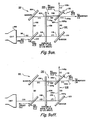
- FIG. 11 is a cross-sectional view of a trichromatic selection assembly according to the present invention, in a first state;
- FIG. 12 is a table displaying the orientation of the dichromatic light beams of FIG. 11, as a function of the state of the first and second variable wave plates;
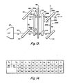
- FIG. 13 is a cross-sectional view of the trichromatic selection assembly of FIG. 11, in a second state;
- FIG. 14 is a table displaying the orientation of the dichromatic light beams of FIG. 13, as a function of the state of the first and second variable wave plates;
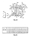
- FIG. 15 is a cross-sectional view of the trichromatic selection assembly of FIG. 11, in a third state; and
- FIG 16 is a table displaying the orientation of the dichromatic light beams of FIG. 15, as a function of the state of the first and second variable wave plates.
- Cholesteric Light Crystals exhibit circular dichroism. They are able to discriminate between Left Handed Circularly Polarized Light ("LHCPL") and Right Handed Circularly Polarized Light ("RHCPL"). If unpolarized light is incident upon a Cholesteric Liquid Crystal element, one sense of circular polarization will be transmitted and the other will be totally reflected.
- FIG. 1 shows a prior art
spectral notch filter 10 composed of a Right Handed Cholesteric Liquid Crystal ("RHCLC") 12. The nominal notch center wavelength ("WL") is a function of the index of refraction of theRHCLC 12 and the period or pitch of the chiral structure. TheRHCLC 12 is optically clear to a first beam of incident light 14, whose wavelength is outside the center band of thefliter 10. - Accordingly, the first light beam 14 is completely transmitted through
RHCLC 12. A second beam of incident light 16, which is at or around wavelength WL and within the center band, is circularly polarized into its component first andsecond beams polarized beam 18, which is Right Handed Circularly Polarized Light ("RHCPL"), is almost totally reflected fromRHCLC 12. The secondpolarized beam 20, which is Left Handed Circularly Polarized Light ("LHCPL"), is almost totally transmitted throughRHCLC 12. Thus thesingle RHCLC 12 provides aspectral notch filter 10 which reflects approximately 50% of the incident light at or around wavelength WL, and transmits the remainder of the incident light. - FIG. 2 is a graph showing the relationship between the wavelength of the incident beam and the transmissivity of the light incident on the
spectral notch filter 10 of FIG. 1. As shown, the "notch" around the center of the wavelength is distinctive. - An improved prior art
spectral notch filter 22 is illustrated in FIG. 3. Theimproved filter 22 is composed of a Left Handed Cholesteric Liquid Crystal ("LHCLC") 24 and a RHCLC 26, similar to RHCLC 12. TheLHCLC 24 transmits incident beam 14a, whose wavelength is outside of the center band and polarizes incident beam 16a, whose wavelength is within the center band or notch, into LHCPL beam 18a and RHCPL beam 20a. LHCPL beam 18a is reflected fromLHCLC 24 and RHCPL 20a is transmitted throughLHCLC 24. The RHCPL beam 20a then impinges upon RHCLC 26 from which it is fully reflected and is transmitted throughLHCLC 24. - As an improvement over the
spectral notch filter 10 of FIG. 1, thespectral notch filter 22 of FIG. 3 provides for near 100% reflectivity of the incident light which is at or near the wavelength WL, the spectral "notch" of the filter. All light outside the notch is transmitted without change. - A variation of the
spectral notch filter 22 of FIG. 3 is illustrated in FIG. 4. The alternative prior artspectral notch filter 30 is composed of two identical CLC's, in this case a pair of LHCLC's, 24a and 24b. A half wave plate 32 is interposed between the LHCLC's 24a and 24b. -
Incident light 16b is polarized by the first LHCLC 24a into aprimary RHCPL beam 20b and1HCPL beam 18b. TheLHCPL beam 18b is reflected by the first LHCLC 24a. Theprimary RHCPL beam 20b is transmitted by the first LHCLC 24a, converted to asecondary LHCPL beam 34 by the half wave plate 32 which is reflected by thesecond LHCLC 24b. Thesecondary LHCPL beam 34 then traverses the half wave plate 32 and is converted to theRHCPL beam 36 which is transmitted by the first LHCLC 24a. - The
spectral notch filter 30 of FIG. 4 therefore reflects virtually 100% of the incident light which is within the "notch", at or near the wavelength WL. As before, all illumination outside the center band is transmitted without modification. - FIG. 5 is a graph showing the performance of an ideal prior art spectral notch CLC filter. Nearly all of the light whose wavelength is outside the band whose center is the wavelength wL will be transmitted. As the wavelength of the incident light approaches the band whose center is WL, transmissivity approaches zero. As shown, the transition between transmission and exclusion can be quite abrupt.
- In an alternative embodiment, the wave plate 32 of FIG. 4 can be replaced by an active variable retarder element (not shown), such as is taught, for example in the U.S. Patent No. 4,770,500 to Kalmanash et al and assigned to the assignee of the present invention. As the retardation is varied from zero to half-wave, the notch transmission can be dynamically varied from 50% to near zero, creating an optical "switch".
- As illustrated in FIG. 6., CLC's in combinations with a such variable retarder can be used to make a color selection filter 38, without using absorptive color polarizers. A similar device was shown in Buzak, U.S. Pat. No. 4,726,663.
- At the bottom of FIG. 6 is a table of the various polarization orientations of the spectral beams at various transmission points within the device.
- As shown, the color selection filter 38 is composed of a cathode ray tube ("CRT") 40 as a light source, a series of CLC's, 42, 44, 46 and 48, and a variable retarder, 50. The
CRT 40 provides an unpolarized light beam 52 which combines narrow wavelength bands ofred light 52r and green light 52g. The unpolarized light beam 52, emitted from theCRT 40 is first incident upon a first RHCLC 42 which is tuned to the red wavelength band of theCRT 40. The red portion of theunpolarized light beam 52r is polarized by the RHCLC 42, transmitting a LHCPred light beam 54r and reflecting a RHCPred light beam 56r. The green portion of the unpolarized light beam 52g is unaffected by the RHCLC 42 and is tranmitted therethrough. - The RHCLC 44 which is tuned to green wavelength band of the
CRT 40, polarizes the green portion of the unpolarized light beam 52g, transmitting a LHCPgreen light beam 58g and reflecting RHCP green light 60g. The LHCPred light beam 54r which is incident on theRHCLC 40 is unaffected by it and is transmitted therethrough. The transmitted beams of LHCP red 54r and LHCP green 58g are acted on by thevariable retarder 50. when thevariable retarder 50 is in the "ON" state, it functions as a zero-wave retarder and transmits circularly polarized light without change. In the "OFF" state, however, thevariable retarder 50 functions as a half-wave retarder and inverts the sense of polarization of the light beams. In this "OFF" configuration, then both the LHCPred light beam 54r and the LHCPgreen light beam 58g are converted to RHCP light beams. - When the
variable retarder 50 is in the "ON" state, the red and green LHCP light beams 54 r and 58g are transmitted through athird RHCLC 46, which is tuned to the green wavelength of the CRT, and a first PLC 48, which is tuned to the red wavelength of the CRT. Thegreen light beam 58g is transmitted to the observer by theRHCLC 46 and thered light beam 54r is totally reflected by the LHCLC 48, thereby resulting in a green image. Thus, the overall transmission of green light is 50% and the overall transmission of red light is zero. - Conversely, when the
variable retarder 50 is in the "OFF" state, RHCP red and green beams, which are depicted as dashedlines 54r′ and 58g′ respectively, impinge on theRHCLC 46. The RHCP green beam is reflected but the RHCP red beam is transmitted through the LHCLC 48, resulting in a red image at the observer. In this configuration the overall transmission of red light is 50% and the overall transmission of green light is zero. - The prior art assembliesof FIGS. 1, 3, 4, 5, and 6, discussed above as color switches, permit a higher transmission rate than is presently attainable through the utilization of absorptive elements. Nevertheless, these CLC based assemblies still carry a 50% insertion loss due to the initial reflection from the first active CLC surface. The preferred embodiment of the present invention eliminates this shortcoming by capturing the circularly polarized light which is reflected from the first, active CLC element, thus enabling a zero-loss, virtually 100% transmission optical switch or color selection element.
- FIG. 7 illustrates the preferred embodiment of the invention as a monochrome
optical switch 60. Unpolarized light 62 from source 64, with spectral content concentrated in a defined region around wavelength WL, is transmitted along path A and is incident on afirst RHCLC 66.Light beam 62 is polarized into aRHCP light beam 68, which is transmitted along path B, and aLHCP beam 70, which is transmitted along path E. TheLHCP light beam 70 is transmitted through avariable wave plate 72. When thevariable wave plate 72 is in the "ON" state, there is zero retardation and theLHCP light beam 70 is transmitted unchanged, following path F. LHCPlight beam 70 is next incident on afirst phase mirror 74, where it undergoes a phase reversal to RHCP light beam 76 and is reflected along path G. - The
RHCP light beam 68, along path B, is incident on asecond phase mirror 78, where it undergoes a phase reversal and is reflected along path C as aLHCP light beam 80. TheLHCP light beam 80 is tranmitted throughvariable wave plate 72, which is in the "ON" state, where it is transmitted unchanged as aLHCP light beam 80 along path D. The RHCP light beam 76, along path G, and theLHCP light beam 80, along path D, are both incident upon asecond RHCLC 82. The RHCP light beam 76 is reflected by thesecond RHCLC 82 and theLHCP light beam 80 is transmitted through thesecond RHCLC 82. Both the RHCP light beam 76 and theRHCP light beam 80 are recombined aslight beam 84 in thesecond RHCLC 82 and transmitted to observer 86. - Thus, with the
variable wave plate 72 in the "ON" state, the net transmission of light to the observer 86 is 100%. A second observer 86′ positioned along the extension of path G would see no light. - When the
variable wave plate 72 is set to the "OFF" state there is half-wave retardation. TheLHCP light beam 70 passes through thevariable wave plate 72 and undergoes a phase reversal and becomes aRHCP light beam 88, denoted by a dashed line. It is then incident upon thefirst phase mirror 74 where it again undergoes a phase reversal to aLHCP light beam 90 and is reflected along path G to thesecond RHCLC 84. - The
LHCP light beam 80 also undergoes phase reversal throughvariable wave piate 72, to become a RHCP light beam 92, also denoted by a dashed line, and is transmitted along path D to thesecond RHCLC 74 where it is reflected. The RHCP light beam 92, which has been reflected by thesecond RHCLC 82, is recombined with theLHCP light beam 90, which has been transmitted through thesecond RHCLC 82. Both beams 92 and 90 are transmitted away from the observer 86, resulting in a net zero transmission of light. - In both the "ON" of "OFF" state, the net result is the 100% transmission of light of a particular wavelength and the 100% reflection of light of other wavelengths. Since there is virtually no absorption of light, the optical switch functions as a "light steering device". Thus, with the second observer 86′, light of the desired wavelength could alternatively be "steered" between observer 86 and observer 86′.
- FIG. 8 is a table illustrating the various polarization orientations of the light beams, depending on the state of the
variable wave plate 72, and the resultant transmission percentage at the observer 86. - In an alternative version of the preferred embodiment, the invention can be used to create a color selection device with the same enhancements in transmissivity. FIG. 9-ON illustrates just such a
color selection assembly 94. In this particular embodiment, thelight source 96 is a CRT which transmits alight beam 98 along path A, which is composed of both red and green light.Light beam 98 is incident upon afirst CLC combination 100, which is composed of a green RHCLC and a red RHCLC. - The
first CLC combination 100 reflects a red and green RHCPlight beam 102 along path B. TheRHCP light beam 102 is incident upon a first phase mirror 104 where it undergoes a phase reversal to a LHCPlight beam 106 and is reflected along path C. The LHCPlight beam 106 passes through avariable wave plate 108, which in this configuration is in the "ON" or zero-wave state. The LHCPlight beam 106 beam is transmitted unchanged along path D. - The LHCP
light beam 106 is incident upon asecond CLC combination 110, which is composed of a green RHCLC and a red LHCLC. The green portion 112g of the LHCPlight beam 106 is thereby transmitted to theobserver 114 and thered portion 116r of the LHCPlight beam 106 is reflected away from theobserver 114 toward analternate observer 114′. - The initial incidence of red and
green light 98 upon thefirst CLC combination 100 also results in the transmission of a red and green LHCPlight beam 118, along path E, through thevariable wave plate 108, where it is transmitted, unchanged along path F. The LHCPlight beam 118 is incident upon asecond phase mirror 120 where it undergoes a phase reversal to aRHCP light beam 122 and is reflected along path G. TheRHCP light beam 122 is then incident uponsecond CLC combination 110, where thered portion 124r of theRHCP light beam 122 is recombined with thered portion 116r of the LHCPlight beam 106 to form red light beam 126r and transmitted away from theobserver 114, along path I, toalternate observer 114′. - The green portion 128g of the
RHCP light beam 122 is reflected by the second combinedCLC 110, where it is recombined with the green portion 112g of the LHCPlight beam 106 to form green light beam 130g along path H and transmitted to theobserver 114. Thus the net transmission of green light toobserver 114 is 100% and the net transmission of red light is zero. However, thealternate observer 114′ "sees" 100% of the red light and no green light. - If the half-
wave plate 108 is set to the "OFF" or half-wave state (see FIG. 9-OFF), then the LHCPlight beam 106 and the LHCPlight beam 118 undergo phase changes and become RHCP light beams. In this configuracion, the LHCPlight beam 106 undergoes phase reversal and becomes RHCP light beam 131, which is composed ofred light beam 132r and green light beam 134g, and is transmitted along path D. The RHCP light beam 131 is then incident upon the second combinedCLC 110, where thered portion 132r of the RHCP light beam 131 is reflected away from theobserver 114 and the green portion 134g of the RHCP light beam 131 is transmitted to theobserver 114. - The LHCP
light beam 118 also undergoes phase reversal to become RHCP light beam 136 and is transmitted along path F. The RHCP light beam 136 is incident uponsecond phase mirror 120, where it undergoes another phase reversal to become LHCPlight beam 138 and is reflected along path G. - LHCP
light beam 138 is incident upon the second combinedCLC 110, where the red portion 140r of the LHCPlight beam 138 is reflected and recombined withred light beam 132r to form red light beam 142r, along path H, and transmitted to theobserver 114. The green portion 144g of the LHCPlight beam 138 is transmitted through the second combinedCLC 110, where it is recombined with green light beam 134g to formgreen light beam 146g and is transmitted away from theobserver 114, along path I, to thealternate observer 114′. Thus, to theobserver 114, the net transmission of red light is 100% and the net transmission of green light is zero, while thealternate observer 114′ "sees" 100% of the green light and none of the red light. - FIG. 10 is a table illustrating the various polarization orientations of the light beams, depending on the state of the
variable wave plate 108, and the resultant transmission percentage at theobserver 114. As is evident, either color can be selected for a zero-loss, net transmission of 100% of the initial incident beam. - Again, since there is virtually no absorption of light, the color selection switch functions as a "color steering device". Since there is 100% transmission of light of a particular wavelength and 100% reflection of light of a second wavelength, light of the first wavelength could alternatively be "steered" between
observer 114 andobserver 114′. Conversely, light of the second wavelength would be "steered" betweenobserver 114′ and 114, respectively. - Furthermore, the near clarity of the CLC's provides for near 100% transmission of light having wavelengths other than the first or second wavelength, which in the above example would be colors other than red or green. Thus, an image composed of these alternative wavelengths, and arriving from another source, could be transmitted through the
last CLC combination 110 and be superimposed upon the transmitted image 130g or 142r. Even if the image from another source had components within the first and second wavelengths, the combinedCLC 110 would still transmit 50% of the light composed of the first and second wavelengths. - The use of the foregoing assembly is readily extendible to a three color selection switch, as illustrated in FIGS. 11, 12, and 13. In FIG. 11, a three color selection assembly is illustrated wherein a
light source 96′ is a CRT which transmits alight beam 98′ which is composed of red, green and blue light.Light beam 98′ is incident upon afirst CLC combination 148 which is composed of a red RHCLC, a green RHCLC and a blue RHCLC. - The
first CLC combination 148 reflects a red, green and blue righthanded light beam 150 along path B. TheRHCP light beam 150 is incident upon afirst phase mirror 152 where it undergoes a phase reversal to LHCPlight beam 154 and is reflected along path C. LHCPlight beam 154 is incident upon a firstvariable wave plate 156, which is in the ON state, where it is transmitted unchanged along path C′. LHCPlight beam 154 is then incident upon asecond CLC combination 158, which is composed of a blue LHCLC and a green RHCLC. The red and green portions of the LHCPlight beam 154 are transmitted through thesecond CLC combination 156 along path C˝ aslight beam 160. - The blue portion of the LHCP
light beam 154 is reflected by the blue LHCLC of thesecond CLC combination 158 aslight beam 162b. Note that the angle of reflection oflight beam 162b is acutely drawn for ease of reference only. In fact,light beam 162b would be reflected back from thesecond CLC combination 158 at an angle equal to its angle of incidence. Given the assembly as illustrated,light beam 162b would be reflected by bothphase mirror 152 andfirst CLC combination 148 back toCRT 96′. - LHCP
light beam 160, composed of red and green LHCP light, is then incident upon a secondvariable wave plate 164, which is also in the ON state, and is transmitted unchanged along path D. The LHCPlight beam 160 is incident upon athird CLC combination 166, composed of a red LHCLC, a green RHCLC and a blue RHCLC. Thegreen portion 168g of thelight beam 160 is transmitted through thethird CLC combination 164 toobserver 114. Thered portion 170r of thelight beam 160, is reflected by the red LHCLC away fromprimary observer 114 to thealternate observer 114′. - The initial incidence of red, green and blue light upon
first CLC combination 148 also results in the transmission of red, green and blue LHCP light beam 172 along path E, through the firstvariable wave plate 156, where it is transmitted unchanged along path E′. LHCP light beam 172 is then incident upon thesecond CLC combination 158 where the red and green portions of light beam 172 are transmitted along path E˝ aslight beam 174. - Once again, the blue portion of light beam 172 is reflected by the second CLC combination, this time as
light beam 176b. Again the angle of reflection is acutely drawn for ease of reference when in factlight beam 176b will also be reflected back toCRT 96′ where it will be recombined with light beam 162. -
Light beam 174, composed of red and green LHCP, is incident upon the secondvariable wave plate 164 where it is transmitted unchanged along path F and is incident upon asecond phase mirror 176, where it is converted to RHCPlight beam 178 and is transmitted along path G. RHCPlight beam 178 is incident uponthird CLC combination 166 where thegreen portion 180g is reflected along path H and recombined with 168g to form green light beam 184g and transmitted toobserver 114. The red portion 182r oflight beam 178 is transmitted through thethird CLC combination 166, where it is recombined withlight beam 170r to formred light beam 186r and transmitted alongpath 1 toalternate observer 114′. - Thus, to the
observer 114, the net transmission of green light is 100% and the net transmission of red light is zero, while thealternate observer 114′ "sees" 100% of the red light and none of the green light. From an initial transmission of red, green and blue light we have "steered" blue light back to its source, green light toobserver 114 and red light toobserver 114′, all with virtually no absorption loss. Again, an image composed of alternative wavelengths, and arriving from another source, could be transmitted through thelast CLC combination 166 and be superimposed upon the transmittedimages 184g or 186r. - FIG. 12 is a table illustrating the various polarization orientations of the light beams further determined by the configuration of the
variable wave plate 158 as indicated in FIG 11. In this configuration green is selected for a zero-loss, net transmission of 100% of the initial incident beam to theobserver 114. - Alternative color selections can be accomplished effected by varying the state of either or both of the
variable wave plates wave plates observer 114 andred light 186r toobserver 114′. - In FIG. 13, the
first wave plate 156 is in the ON state and thesecond wave plate 164 is in the OFF state. Thus, LHCPlight beam 154 passes through thefirst wave plate 156 and is converted to RHCPlight beam 188 and transmitted along path C′. RHCPlight beam 188 is transmitted through thesecond CLC combination 158, where green RHCPlight beam 190g is reflected and light beam 392, composed of red and blue RHCP light, is tranmsitted along path C˝. RNCPlight beam 192 is transmitted through thesecond wave plate 164 and is transmitted unchanged along path D and is incident upon thethird CLC combination 166. Thered portion 194r of RHCPlight beam 192 is transmitted along path H toobserver 114 and theblue portion 196b of RHCPlight beam 192 is reflected along path I toobserver 114′. - The RHCP light beam 172 passes through the
first wave plate 156 and is converted to LHCPlight beam 198 and transmitted along path E′. RHCPlight beam 198 is transmitted through thesecond CLC combination 158, where green RHCPlight beam 200g is reflected andlight beam 202, composed of red and blue RHCP light, is transmitted along path E˝. RHCPlight beam 202 is transmitted unchanged through thesecond wave plate 164 and is incident upon thesecond phase mirror 176, where it is converted to LHCPlight beam 204 and reflected along path G and it is incident upon thethird CLC combination 166. Thered portion 206r of RHCPlight beam 204 is reflected along path H where it is recombined withred light beam 194r to become 210r and transmitted toobserver 114. Theblue portion 208b of RHCPlight beam 204 is transmitted along path I where it is recombined with bluelight beam 196b to become bluelight beam 212b and transmitted toobserver 114′. Thus, we have steered nearly 100% of the red light toobserver 114 and nearly 100% of the blue light toobserver 114′. Again the unwanted color, in this case green, has been nearly wholly reflected back toCRT 96′. - FIG. 14 is a table illustrating the various polarization orientations of the light beams further determined by the configuration of the
variable wave plate 158 as indicated in FIG 13. In this configuration red is selected for a zero-loss, net transmission of 100% of the initial incident beam to theobserver 114. - In yet another configuration, that of FIG. 15, we are able to select the blue color and send it to
observer 114 and send red toobserver 114′. This is accomplished by placing both thefirst wave plate 156 and thesecond wave plate 164 in the OFF state. In this configuration, LHCPlight beam 154 passes through thefirst wave plate 156 and is again converted to RHCPlight beam 188 and transmitted along path C′. RHCPlight beam 188 is transmitted through thesecond CLC combination 158, where green RHCPlight beam 190g is reflected andlight beam 192, composed of red and blue RHCP light, is tranmsitted along path C˝. RHCPlight beam 192 is transmitted through thesecond wave plate 164 where this time it converted to LHCPlight beam 214 and transmitted along path D. LHCPlight beam 214 is incident upon thethird CLC combination 166 where theblue portion 216b of LHCPlight beam 214 is transmitted along path H toobserver 114 and thered portion 218r of LHCPlight beam 214 is reflected along path I toobserver 114′. - The RHCP light beam 172 passes through the
first wave plate 156 and is again converted to LHCPlight beam 198 and transmitted along path E′. RHCPlight beam 198 is again transmitted through thesecond CLC combination 158, where green RHCPlight beam 200g is reflected andlight beam 202, composed of red and blue RHCP light, is transmitted along path E˝. RHCPlight beam 202 is transmitted through thesecond wave plate 164 where it is converted to LHCPlight beam 220 and is incident upon thesecond phase mirror 176, where it is converted to RHCPlight beam 222 and reflected along path G. RHCPlight beam 222 is incident upon thethird CLC combination 166 where theblue portion 224b of RHCPlight beam 222 is transmitted along path H where it is recombined with bluelight beam 216b to become 228b and transmitted toobserver 114. Thered portion 226r of RHCPlight beam 222 is transmitted along path I where it is recombined with bluelight beam 218r to becomered light beam 230r and transmitted toobserver 114′. In this configuration, we have steered nearly 100% of the blue light toobserver 114 and nearly 100% of the red light toobserver 114′. Again the unwanted color, green, has been nearly wholly reflected back toCRT 96′. - FIG. 16 is a table illustrating the various polarization orientations of the light beams further determined by the configuration of the
variable wave plate 158 as indicated in FIG 15. In this configuration blue is selected for a zero-loss, net transmission of 100% of the initial incident beam to theobserver 114. - In yet another configuration of the three color selection assembly, red is again transmitted to the
observer 114, with green being sent tothealternate observer 114′. This is accomplished by placing thefirst wave plate 156 in the ON state and thesecond wave plate 164 in the OFF state, the converse of the configuration of FIG. 12. In this configuration, it is the blue light that is reflected by thesecond CLC combination 158, and the green light that is transmitted, ultimately, to thealternate observer 114′. - In summation, the three color selection assembly of FIGS. 11, 13 and 15, provide for the choice of two colors from an initial incident beam composed of three colors. If both variable wave plates are in the ON state, then green light is transmitted to
observer 114. If both variable wave plates are in the OFF state, then blue light is transmitted toobserver 114. Finally, if the variable wave plates are in different states from each other, then red light is transmitted toobserver 114. In the later instance, the selection of color sent to thealternate observer 114′ is determined by which variable wave plate is in the ON state. - By varying the "tuning" of the CLC combinations and by altering the states of the variable wave plates, various permutations and combinations of color selection can be accomplished, in addition to those discussed above, resulting in a virtual palette of colors available for display. The uses of the foregoing assemblies are thus extendible to a multi-color operation that is suitable for use with any color light source.
- Moreover, while monomer cholesteric liquid crystals have been employed in these embodiments, it is believed that polymer cholesteric liquid crystals, which are much more insensitive to temperature variations, would be preferable in those applications where the temperature cannot be closely controlled. The present embodiments of this invention are thus to be considered in all respects as illustrative and not restrictive; the scope of invention being indicated by the appended claims rather than the foregoing description. All changes which come within the meaning and range of equivalency of the claims are intended to be embraced therein.
Claims (23)
1. An apparatus for providing optical switching of a nonpolarized beam of light by an observer comprising:
(a) first beam separating means adapted to receive the beam of light, for transmitting a first portion of said slight beam having a first polarization orientation and for reflecting a second portion of said light beam having a second polarization orientation;
(b) first wave orientation reversal means in optical communication with said first beam separating means, for reversing the orientation of and reflecting said reflected second portion of said light beam;
(c) variable wave retardation means, adapted for receiving and transmitting light from said first beam separating means and from said first wave orientation reversal means, for selectively retarding the polarization orientation of light transmitted therethrough;
(d) second wave orientation reversal means in the path of said first light beam portion for reversing the orientation of light transmitted through said variable wave retardation means and for reflecting said first light beam portion;
(e) second beam separating means adapted for receiving said first and second light beam portions from said second wave orientation reversal means and said variable wave retardation means, respectively, and further adapted for transmitting those light beam portions having said first orientation and for reflecting those light beam portions having said second orientation.
2. The apparatus of claim 1, further including controlling means operatively coupled to said variable wave retardation means adapted for use by the observer to selectively retard the polarization orientation of light transmitted through said variable wave retardation means.
3. The apparatus of claim 1, wherein said first and said second beam separating means are polarizing notch filters adapted for reflecting light of a chosen wavelength and orientation and for transmitting all other beams of light.
4. The apparatus of claim 3, wherein said polarizing notch filters means are further adapted for selectively transmitting and reflecting light of at least one chosen wavelength and and at least one chosen orientation.
5. The apparatus of claim 3, wherein said wavelengths are within the visible spectrum.
6. The apparatus of claim 1, wherein the first and second beam separating means include cholesteric liquid crystals.
7. The apparatus of claim 6, wherein said cholesteric liquid crystals include monomer cholesteric liquid crystals.
8. The apparatus of claim 6, wherein said cholesteric liquid crystals include polymer cholesteric liquid crystals.
9. The apparatus of claim 1, wherein said first and second wave phase reversal means include mirrors.
10. An apparatus for providing wavelength selection of a nonpolarized beam of light of more than one wavelength by an observer comprising:
(a) first beam separating means adapted to receive the beam of light, for transmitting a first light beam portion having a first polarization orientation and for reflecting a second light beam portion having a second polarization orientation;
(b) first wave orientation reversal means in optical communication with said first beam separating means, for reversing the orientation of and reflecting said second light beam portion;
(c) variable wave retardation means adapted for for receiving and transmitting said first and second light beam portions, and for selectively retarding the polarization orientation of said light beam portions transmitted therethrough;
(d) second wave orientation reversal means in the path of said first light beam portion for reversing the orientation of said first light beam portion transmitted through said variable wave retardation means and for reflecting said first light beam portion;
(e) second beam separating means adapted for receiving said first and second light beam portions and for transmitting those light beam portions having a selected wavelength and orientation combination and for reflecting those nonselected wavelength and orientation combinations.
11. The apparatus of claim 10, further including controlling means adapted for use by the observer to selectively retard the polarization orientation of light transmitted through said variable wave retardation means.
12. The apparatus of claim 10, wherein said first and said second beam separating means include polarizing notch filters adapted for reflecting light beams of a chosen wavelength and orientation and for transmitting all other beams of light.
13. The apparatus of claim 12, wherein said first and second beam separating means are further adapted for selectively transmitting and reflecting light beams of at least one chosen wavelength and at least one chosen orientation.
14. The apparatus of claim 10, further including a third beam separating means operatiylely connected to said variable wave retardation means and adapted for reflecting light of a chosen wavelength and orientation and for transmitting all other beams of light.
15. The apparatus of claim 10, further including a second wave retardation means operatively connected to said first variable wave retardation means and adapted for selectively retarding the polarization orientation of said portions of light transmitted therethrough.
16. The apparatus of claim 10, wherein said wavelengths correspond to visible light.
17. The apparatus of claim 10 wherein the first and second beam separating means include cholesteric liquid crystals.
18. The apparatus of claim 16, wherein said cholesteric liquid crystals include monomer cholesteric liquid crystals.
19. The apparatus of claim 16, wherein said cholesteric liquid crystals include polymer cholesteric liquid crystals.
20. The apparatus of claim 10 wherein said first and second wave orientation reversal means include mirrors.
21. The apparatus of claim 10, wherein said first beam separating means is a combination of cholesteric liquid crystals adapted to selectively reflect and transmit wavelengths of light based upon their given orientations.
22. The apparatus of claim 10, wherein said second beam separating means is a combination of cholesteric liquid crystals adapted to selectively reflect and transmit wavelengths of light based upon their given orientations.
23. An apparatus for providing wavelength selection of a nonpolarized beam of light of more than one wavelength by an observer comprising:
(a) first cholesteric liquid crystal combination adapted to receive the beam of light, for reflecting a first light beam portion of a chosen polarization orientation and for transmitting a second light beam portion composed of all other polarization orientations;
(b) first mirror in optical communication with said first cholesteric liquid crystal combination, for reversing the orientation of and reflecting said second light beam portion;
(c) first variable wave retardation means adapted for receiving said first and second light beam portions and for selectively retarding the polarization orientation of said light beam portions transmitted therethrough;
(d) second cholesteric liquid crystal combination in optical communication with said first variable wave retardation means and adapted for receiving said first and said second light beam portions transmitted through said first variable wave retardation means, for reflecting portions of said first and second light beam portions of a chosen orientation and for tranmitting other selected portions of said first and second light beam portions composed of all other orientations;
(e) second variable wave retardation means in optical communication with said second cholesteric liquid crystal combination adapted for receiving said selected portions of light transmitted through said second cholesteric liquid crystal combination, and for selectively retarding the polarization orientation of said selected portions of light;
(f) controlling means adapted for use by the observer to selectively retard the polarization orientation of light transmitted through said first and said second variable wave retardation means;
(g) second mirror in optical communication with said second variable wave retardation means adapted for reversing the orientation of said selected portion of said second light beam portion transmitted through said variable wave retardation means and for reflecting said selected portion of light;
(h) third cholestereic liquid crystal combination adapted for receiving said selected portions of said first and said second light beam portions and for transmitting those selected portions of light having a selected wavelength and orientation combination and for reflecting those nonselected wavelength and orientation combinations.
Applications Claiming Priority (2)
| Application Number | Priority Date | Filing Date | Title |
|---|---|---|---|
| US07/400,156 US5082354A (en) | 1989-08-29 | 1989-08-29 | Optical switch and color selection assembly |
| US400156 | 2002-08-01 |
Publications (2)
| Publication Number | Publication Date |
|---|---|
| EP0415735A2 true EP0415735A2 (en) | 1991-03-06 |
| EP0415735A3 EP0415735A3 (en) | 1992-01-15 |
Family
ID=23582446
Family Applications (1)
| Application Number | Title | Priority Date | Filing Date |
|---|---|---|---|
| EP19900309437 Withdrawn EP0415735A3 (en) | 1989-08-29 | 1990-08-29 | Optical switch and color selection assembly |
Country Status (5)
| Country | Link |
|---|---|
| US (1) | US5082354A (en) |
| EP (1) | EP0415735A3 (en) |
| JP (1) | JPH03144419A (en) |
| CA (1) | CA2024163A1 (en) |
| IL (1) | IL94603A0 (en) |
Cited By (20)
| Publication number | Priority date | Publication date | Assignee | Title |
|---|---|---|---|---|
| EP1411383A1 (en) * | 2002-10-14 | 2004-04-21 | Agilent Technologies, Inc. - a Delaware corporation - | Surface plasmon resonance optical notch filter apparatus and method therefor |
| EP1498751A1 (en) * | 2002-04-23 | 2005-01-19 | Nitto Denko Corporation | Polarizer, polarization light source and image displayunit using them |
| EP3165949A4 (en) * | 2014-07-01 | 2018-04-18 | Nippon Kayaku Kabushiki Kaisha | Optical film and optical laminate using same |
| WO2018156784A1 (en) * | 2017-02-23 | 2018-08-30 | Magic Leap, Inc. | Variable-focus virtual image devices based on polarization conversion |
| US10466561B2 (en) | 2016-12-08 | 2019-11-05 | Magic Leap, Inc. | Diffractive devices based on cholesteric liquid crystal |
| US10895784B2 (en) | 2016-12-14 | 2021-01-19 | Magic Leap, Inc. | Patterning of liquid crystals using soft-imprint replication of surface alignment patterns |
| US10908423B2 (en) | 2016-11-18 | 2021-02-02 | Magic Leap, Inc. | Multilayer liquid crystal diffractive gratings for redirecting light of wide incident angle ranges |
| US10921630B2 (en) | 2016-11-18 | 2021-02-16 | Magic Leap, Inc. | Spatially variable liquid crystal diffraction gratings |
| US10948642B2 (en) | 2015-06-15 | 2021-03-16 | Magic Leap, Inc. | Display system with optical elements for in-coupling multiplexed light streams |
| US10969588B2 (en) | 2015-03-16 | 2021-04-06 | Magic Leap, Inc. | Methods and systems for diagnosing contrast sensitivity |
| US11067860B2 (en) | 2016-11-18 | 2021-07-20 | Magic Leap, Inc. | Liquid crystal diffractive devices with nano-scale pattern and methods of manufacturing the same |
| US11073695B2 (en) | 2017-03-21 | 2021-07-27 | Magic Leap, Inc. | Eye-imaging apparatus using diffractive optical elements |
| US11106041B2 (en) | 2016-04-08 | 2021-08-31 | Magic Leap, Inc. | Augmented reality systems and methods with variable focus lens elements |
| US11204462B2 (en) | 2017-01-23 | 2021-12-21 | Magic Leap, Inc. | Eyepiece for virtual, augmented, or mixed reality systems |
| US11237393B2 (en) | 2018-11-20 | 2022-02-01 | Magic Leap, Inc. | Eyepieces for augmented reality display system |
| US11269144B2 (en) | 2017-03-21 | 2022-03-08 | Magic Leap, Inc. | Stacked waveguides having different diffraction gratings for combined field of view |
| US11347063B2 (en) | 2017-12-15 | 2022-05-31 | Magic Leap, Inc. | Eyepieces for augmented reality display system |
| US11378864B2 (en) | 2016-11-18 | 2022-07-05 | Magic Leap, Inc. | Waveguide light multiplexer using crossed gratings |
| US11650423B2 (en) | 2019-06-20 | 2023-05-16 | Magic Leap, Inc. | Eyepieces for augmented reality display system |
| US11841481B2 (en) | 2017-09-21 | 2023-12-12 | Magic Leap, Inc. | Augmented reality display with waveguide configured to capture images of eye and/or environment |
Families Citing this family (14)
| Publication number | Priority date | Publication date | Assignee | Title |
|---|---|---|---|---|
| US5325218A (en) * | 1992-12-31 | 1994-06-28 | Minnesota Mining And Manufacturing Company | Cholesteric polarizer for liquid crystal display and overhead projector |
| DE4328785A1 (en) * | 1993-08-26 | 1995-03-02 | Consortium Elektrochem Ind | Optical elements with imaging color and polarization selective reflection containing cholesteric liquid crystals and the production and use of these elements |
| US5619355A (en) * | 1993-10-05 | 1997-04-08 | The Regents Of The University Of Colorado | Liquid crystal handedness switch and color filter |
| US5408346A (en) * | 1993-10-20 | 1995-04-18 | Kaiser Electro-Optics, Inc. | Optical collimating device employing cholesteric liquid crystal and a non-transmissive reflector |
| US5835166A (en) * | 1994-08-17 | 1998-11-10 | Hall; Dennis R. | Chiral nematic liquid crystal polarization modulated color display for stereoscopic viewing device |
| US5892559A (en) | 1996-11-25 | 1999-04-06 | Colorlink, Inc. | Chromaticity compensating liquid crystal filter |
| US6563553B1 (en) * | 1997-01-16 | 2003-05-13 | Reveo, Inc. | Flat panel display and method of manufacture |
| US6680758B1 (en) | 1997-01-16 | 2004-01-20 | Reveo, Inc. | Flat panel display and a method of fabrication |
| DE19737618A1 (en) | 1997-08-28 | 1999-03-04 | Consortium Elektrochem Ind | Machine-detectable security marking with increased protection against forgery, production of the security marking and security system comprising this security marking |
| EP1153329A4 (en) * | 1998-12-24 | 2005-11-23 | Reveo Inc | Flat panel image display structures and method of manufacture |
| WO2001057587A1 (en) * | 2000-02-03 | 2001-08-09 | Rolic Ag | Colour switch |
| US6580845B1 (en) | 2000-08-11 | 2003-06-17 | General Nutronics, Inc. | Method and device for switching wavelength division multiplexed optical signals using emitter arrays |
| FR2878041B1 (en) * | 2004-11-18 | 2007-10-26 | Eads Astrium Sas Soc Par Actio | OPTICAL SEPARATION DEVICE AND OPTICAL COMMUNICATION TERMINAL COMPRISING SUCH A DEVICE |
| WO2019135197A1 (en) * | 2018-01-05 | 2019-07-11 | 3M Innovative Properties Company | Light directing article with a patterned retarder |
Citations (5)
| Publication number | Priority date | Publication date | Assignee | Title |
|---|---|---|---|---|
| EP0080343A1 (en) * | 1981-11-19 | 1983-06-01 | Sperry Corporation | Optical bypass switch |
| EP0138454A2 (en) * | 1983-09-26 | 1985-04-24 | Tektronix, Inc. | Switchable color filter and field sequential full color display system incorporating same |
| US4726663A (en) * | 1986-11-14 | 1988-02-23 | Tektronix, Inc. | Switchable color filter with enhanced transmissivity |
| EP0271641A1 (en) * | 1981-12-07 | 1988-06-22 | GTE Laboratories Incorporated | Polarization-insensitive optical switch and multiplexing apparatus |
| WO1990014606A1 (en) * | 1989-05-19 | 1990-11-29 | Cornell Research Foundation, Inc. | Optical switches using cholesteric or chiral nematic liquid crystals |
Family Cites Families (8)
| Publication number | Priority date | Publication date | Assignee | Title |
|---|---|---|---|---|
| US3679290A (en) * | 1971-01-06 | 1972-07-25 | Xerox Corp | Liquid crystal optical filter system |
| US3711181A (en) * | 1971-03-05 | 1973-01-16 | Xerox Corp | Optical notch filter |
| US4566758A (en) * | 1983-05-09 | 1986-01-28 | Tektronix, Inc. | Rapid starting, high-speed liquid crystal variable optical retarder |
| US4758818A (en) * | 1983-09-26 | 1988-07-19 | Tektronix, Inc. | Switchable color filter and field sequential full color display system incorporating same |
| US4674841A (en) * | 1985-03-08 | 1987-06-23 | Tektronix, Inc. | Color filter switchable among three state via a variable retarder |
| US4726660A (en) * | 1986-05-16 | 1988-02-23 | The United States Of America As Represented By The United States Department Of Energy | Technique for compressing light intensity ranges utilizing a specifically designed liquid crystal notch filter |
| US4770500A (en) * | 1986-06-10 | 1988-09-13 | Kaiser Aerospace And Electronics Corporation | Method and apparatus for multi color display |
| US4913529A (en) * | 1988-12-27 | 1990-04-03 | North American Philips Corp. | Illumination system for an LCD display system |
-
1989
- 1989-08-29 US US07/400,156 patent/US5082354A/en not_active Expired - Fee Related
-
1990
- 1990-06-04 IL IL94603A patent/IL94603A0/en unknown
- 1990-08-08 JP JP2208315A patent/JPH03144419A/en active Pending
- 1990-08-28 CA CA002024163A patent/CA2024163A1/en not_active Abandoned
- 1990-08-29 EP EP19900309437 patent/EP0415735A3/en not_active Withdrawn
Patent Citations (5)
| Publication number | Priority date | Publication date | Assignee | Title |
|---|---|---|---|---|
| EP0080343A1 (en) * | 1981-11-19 | 1983-06-01 | Sperry Corporation | Optical bypass switch |
| EP0271641A1 (en) * | 1981-12-07 | 1988-06-22 | GTE Laboratories Incorporated | Polarization-insensitive optical switch and multiplexing apparatus |
| EP0138454A2 (en) * | 1983-09-26 | 1985-04-24 | Tektronix, Inc. | Switchable color filter and field sequential full color display system incorporating same |
| US4726663A (en) * | 1986-11-14 | 1988-02-23 | Tektronix, Inc. | Switchable color filter with enhanced transmissivity |
| WO1990014606A1 (en) * | 1989-05-19 | 1990-11-29 | Cornell Research Foundation, Inc. | Optical switches using cholesteric or chiral nematic liquid crystals |
Non-Patent Citations (1)
| Title |
|---|
| Optics Letters, Vol. 15, No. 2, January 1990, New York US, pages 145-147; M.G. ROBINSON et al.: "Polarization-independent, broadband, bistable, 2*2 optical exchange switch", page 145; figure 1. * |
Cited By (56)
| Publication number | Priority date | Publication date | Assignee | Title |
|---|---|---|---|---|
| EP1498751A1 (en) * | 2002-04-23 | 2005-01-19 | Nitto Denko Corporation | Polarizer, polarization light source and image displayunit using them |
| EP1498751A4 (en) * | 2002-04-23 | 2007-08-01 | Nitto Denko Corp | Polarizer, polarization light source and image displayunit using them |
| US7443585B2 (en) | 2002-04-23 | 2008-10-28 | Nitto Denko Corporation | Polarizer, polarization light source and image display unit using them |
| US7746555B2 (en) | 2002-04-23 | 2010-06-29 | Nitto Denko Corporation | Polarizer, polarization light source and image display unit using them |
| US7982952B2 (en) | 2002-04-23 | 2011-07-19 | Nitto Denko Corporation | Polarization component, polarization light source and image display apparatus using the same |
| EP1411383A1 (en) * | 2002-10-14 | 2004-04-21 | Agilent Technologies, Inc. - a Delaware corporation - | Surface plasmon resonance optical notch filter apparatus and method therefor |
| US10120206B2 (en) | 2014-07-01 | 2018-11-06 | Nippon Kayaku Kabushiki Kaisha | Optical film and optical laminate using same |
| EP3165949A4 (en) * | 2014-07-01 | 2018-04-18 | Nippon Kayaku Kabushiki Kaisha | Optical film and optical laminate using same |
| US10969588B2 (en) | 2015-03-16 | 2021-04-06 | Magic Leap, Inc. | Methods and systems for diagnosing contrast sensitivity |
| US11747627B2 (en) | 2015-03-16 | 2023-09-05 | Magic Leap, Inc. | Augmented and virtual reality display systems and methods for diagnosing health conditions based on visual fields |
| US11474359B2 (en) | 2015-03-16 | 2022-10-18 | Magic Leap, Inc. | Augmented and virtual reality display systems and methods for diagnosing health conditions based on visual fields |
| US11256096B2 (en) | 2015-03-16 | 2022-02-22 | Magic Leap, Inc. | Methods and systems for diagnosing and treating presbyopia |
| US10983351B2 (en) | 2015-03-16 | 2021-04-20 | Magic Leap, Inc. | Augmented and virtual reality display systems and methods for diagnosing health conditions based on visual fields |
| US11156835B2 (en) | 2015-03-16 | 2021-10-26 | Magic Leap, Inc. | Methods and systems for diagnosing and treating health ailments |
| US11733443B2 (en) | 2015-06-15 | 2023-08-22 | Magic Leap, Inc. | Virtual and augmented reality systems and methods |
| US11789189B2 (en) | 2015-06-15 | 2023-10-17 | Magic Leap, Inc. | Display system with optical elements for in-coupling multiplexed light streams |
| US10948642B2 (en) | 2015-06-15 | 2021-03-16 | Magic Leap, Inc. | Display system with optical elements for in-coupling multiplexed light streams |
| US11067732B2 (en) | 2015-06-15 | 2021-07-20 | Magic Leap, Inc. | Virtual and augmented reality systems and methods |
| US11106041B2 (en) | 2016-04-08 | 2021-08-31 | Magic Leap, Inc. | Augmented reality systems and methods with variable focus lens elements |
| US11614626B2 (en) | 2016-04-08 | 2023-03-28 | Magic Leap, Inc. | Augmented reality systems and methods with variable focus lens elements |
| US11693282B2 (en) | 2016-11-18 | 2023-07-04 | Magic Leap, Inc. | Liquid crystal diffractive devices with nano-scale pattern and methods of manufacturing the same |
| US11586065B2 (en) | 2016-11-18 | 2023-02-21 | Magic Leap, Inc. | Spatially variable liquid crystal diffraction gratings |
| US11067860B2 (en) | 2016-11-18 | 2021-07-20 | Magic Leap, Inc. | Liquid crystal diffractive devices with nano-scale pattern and methods of manufacturing the same |
| US11119327B2 (en) | 2016-11-18 | 2021-09-14 | Magic Leap, Inc. | Multilayer liquid crystal diffractive gratings for redirecting light of wide incident angle ranges |
| US11609480B2 (en) | 2016-11-18 | 2023-03-21 | Magic Leap, Inc. | Waveguide light multiplexer using crossed gratings |
| US11573424B2 (en) | 2016-11-18 | 2023-02-07 | Magic Leap, Inc. | Multilayer liquid crystal diffractive gratings for redirecting light of wide incident angle ranges |
| US10921630B2 (en) | 2016-11-18 | 2021-02-16 | Magic Leap, Inc. | Spatially variable liquid crystal diffraction gratings |
| US11378864B2 (en) | 2016-11-18 | 2022-07-05 | Magic Leap, Inc. | Waveguide light multiplexer using crossed gratings |
| US10908423B2 (en) | 2016-11-18 | 2021-02-02 | Magic Leap, Inc. | Multilayer liquid crystal diffractive gratings for redirecting light of wide incident angle ranges |
| US11256153B2 (en) | 2016-12-08 | 2022-02-22 | Magic Leap, Inc. | Diffractive devices based on cholesteric liquid crystal |
| US10976632B2 (en) | 2016-12-08 | 2021-04-13 | Magic Leap, Inc. | Diffractive devices based on cholesteric liquid crystal |
| US10466561B2 (en) | 2016-12-08 | 2019-11-05 | Magic Leap, Inc. | Diffractive devices based on cholesteric liquid crystal |
| US11668989B2 (en) | 2016-12-08 | 2023-06-06 | Magic Leap, Inc. | Diffractive devices based on cholesteric liquid crystal |
| US10895784B2 (en) | 2016-12-14 | 2021-01-19 | Magic Leap, Inc. | Patterning of liquid crystals using soft-imprint replication of surface alignment patterns |
| US11567371B2 (en) | 2016-12-14 | 2023-01-31 | Magic Leap, Inc. | Patterning of liquid crystals using soft-imprint replication of surface alignment patterns |
| US11733456B2 (en) | 2017-01-23 | 2023-08-22 | Magic Leap, Inc. | Eyepiece for virtual, augmented, or mixed reality systems |
| US11204462B2 (en) | 2017-01-23 | 2021-12-21 | Magic Leap, Inc. | Eyepiece for virtual, augmented, or mixed reality systems |
| US10962855B2 (en) | 2017-02-23 | 2021-03-30 | Magic Leap, Inc. | Display system with variable power reflector |
| WO2018156784A1 (en) * | 2017-02-23 | 2018-08-30 | Magic Leap, Inc. | Variable-focus virtual image devices based on polarization conversion |
| US11982916B2 (en) | 2017-02-23 | 2024-05-14 | Magic Leap, Inc. | Variable-focus virtual image devices based on polarization conversion |
| US11036109B2 (en) | 2017-02-23 | 2021-06-15 | Magic Leap, Inc. | Variable-focus virtual image devices based on polarization conversion |
| US11215895B2 (en) | 2017-02-23 | 2022-01-04 | Magic Leap, Inc. | Variable-focus virtual image devices based on polarization conversion |
| US11774823B2 (en) | 2017-02-23 | 2023-10-03 | Magic Leap, Inc. | Display system with variable power reflector |
| US11714326B2 (en) | 2017-02-23 | 2023-08-01 | Magic Leap, Inc. | Variable-focus virtual image devices based on polarization conversion |
| US11300844B2 (en) | 2017-02-23 | 2022-04-12 | Magic Leap, Inc. | Display system with variable power reflector |
| US11754840B2 (en) | 2017-03-21 | 2023-09-12 | Magic Leap, Inc. | Eye-imaging apparatus using diffractive optical elements |
| US11269144B2 (en) | 2017-03-21 | 2022-03-08 | Magic Leap, Inc. | Stacked waveguides having different diffraction gratings for combined field of view |
| US11803003B2 (en) | 2017-03-21 | 2023-10-31 | Magic Leap, Inc. | Stacked waveguides having different diffraction gratings for combined field of view |
| US11073695B2 (en) | 2017-03-21 | 2021-07-27 | Magic Leap, Inc. | Eye-imaging apparatus using diffractive optical elements |
| US12055726B2 (en) | 2017-03-21 | 2024-08-06 | Magic Leap, Inc. | Eye-imaging apparatus using diffractive optical elements |
| US11841481B2 (en) | 2017-09-21 | 2023-12-12 | Magic Leap, Inc. | Augmented reality display with waveguide configured to capture images of eye and/or environment |
| US11347063B2 (en) | 2017-12-15 | 2022-05-31 | Magic Leap, Inc. | Eyepieces for augmented reality display system |
| US11977233B2 (en) | 2017-12-15 | 2024-05-07 | Magic Leap, Inc. | Eyepieces for augmented reality display system |
| US11237393B2 (en) | 2018-11-20 | 2022-02-01 | Magic Leap, Inc. | Eyepieces for augmented reality display system |
| US11754841B2 (en) | 2018-11-20 | 2023-09-12 | Magic Leap, Inc. | Eyepieces for augmented reality display system |
| US11650423B2 (en) | 2019-06-20 | 2023-05-16 | Magic Leap, Inc. | Eyepieces for augmented reality display system |
Also Published As
| Publication number | Publication date |
|---|---|
| EP0415735A3 (en) | 1992-01-15 |
| CA2024163A1 (en) | 1991-03-01 |
| IL94603A0 (en) | 1991-04-15 |
| US5082354A (en) | 1992-01-21 |
| JPH03144419A (en) | 1991-06-19 |
Similar Documents
| Publication | Publication Date | Title |
|---|---|---|
| US5082354A (en) | Optical switch and color selection assembly | |
| US4726663A (en) | Switchable color filter with enhanced transmissivity | |
| EP0313640B1 (en) | Improved optical system for full color liquid crystal light valve image projection | |
| EP0659024B1 (en) | Illumination system for a colour image projection device and circular polarizer suitable for use in such a system | |
| US5740288A (en) | Variable polarization beam splitter, combiner and mixer | |
| EP0984637B1 (en) | Projection display system for reflective light valves | |
| US5410421A (en) | Optical separator of polarizations and application to a display system | |
| US4191456A (en) | Optical block for high brightness full color video projection system | |
| US4987410A (en) | Multiple image forming apparatus | |
| EP0389240B1 (en) | Polarizing beam splitter apparatus and light valve image projection system | |
| US5272496A (en) | Image projector with optimized luminous efficiency | |
| US4343535A (en) | Liquid crystal light valve | |
| US4719507A (en) | Stereoscopic imaging system with passive viewing apparatus | |
| US6995917B1 (en) | Projection display system using polarized light | |
| US6398364B1 (en) | Off-axis image projection display system | |
| EP0301065B1 (en) | Color sequential illuminating system for a liquid crystal light valve | |
| US4575193A (en) | Optical spatial frequency filter | |
| US6018418A (en) | Polarization beam splitter | |
| US5299036A (en) | Liquid crystal projector including a polaration rotating element | |
| WO1995010065A1 (en) | Liquid crystal handedness switch and color filter | |
| JP2656666B2 (en) | Projection display device | |
| US6082863A (en) | Color projection prism | |
| KR100277325B1 (en) | Reflective Liquid Crystal Device_ | |
| US4911547A (en) | Compact optical system for a single light valve projector using two axes of polarization | |
| EP0083440B1 (en) | Two-color liquid crystal light valve image projection system with prepolarization |
Legal Events
| Date | Code | Title | Description |
|---|---|---|---|
| PUAI | Public reference made under article 153(3) epc to a published international application that has entered the european phase |
Free format text: ORIGINAL CODE: 0009012 |
|
| 17P | Request for examination filed |
Effective date: 19900910 |
|
| AK | Designated contracting states |
Kind code of ref document: A2 Designated state(s): DE FR GB IT NL |
|
| PUAL | Search report despatched |
Free format text: ORIGINAL CODE: 0009013 |
|
| AK | Designated contracting states |
Kind code of ref document: A3 Designated state(s): DE FR GB IT NL |
|
| STAA | Information on the status of an ep patent application or granted ep patent |
Free format text: STATUS: THE APPLICATION IS DEEMED TO BE WITHDRAWN |
|
| 18D | Application deemed to be withdrawn |
Effective date: 19920716 |