EP0415655A2 - Two-wire power and position control system - Google Patents
Two-wire power and position control system Download PDFInfo
- Publication number
- EP0415655A2 EP0415655A2 EP90309267A EP90309267A EP0415655A2 EP 0415655 A2 EP0415655 A2 EP 0415655A2 EP 90309267 A EP90309267 A EP 90309267A EP 90309267 A EP90309267 A EP 90309267A EP 0415655 A2 EP0415655 A2 EP 0415655A2
- Authority
- EP
- European Patent Office
- Prior art keywords
- motor
- impedance
- station
- energizing
- remote station
- Prior art date
- Legal status (The legal status is an assumption and is not a legal conclusion. Google has not performed a legal analysis and makes no representation as to the accuracy of the status listed.)
- Granted
Links
- 238000006073 displacement reaction Methods 0.000 claims abstract description 8
- 230000000694 effects Effects 0.000 claims description 5
- 230000000737 periodic effect Effects 0.000 claims 1
- 239000004020 conductor Substances 0.000 abstract 1
- 238000012544 monitoring process Methods 0.000 abstract 1
- 238000010586 diagram Methods 0.000 description 8
- 230000004048 modification Effects 0.000 description 6
- 238000012986 modification Methods 0.000 description 6
- 239000003990 capacitor Substances 0.000 description 1
- 230000001419 dependent effect Effects 0.000 description 1
- 230000009977 dual effect Effects 0.000 description 1
Images


Classifications
-
- G—PHYSICS
- G08—SIGNALLING
- G08C—TRANSMISSION SYSTEMS FOR MEASURED VALUES, CONTROL OR SIMILAR SIGNALS
- G08C25/00—Arrangements for preventing or correcting errors; Monitoring arrangements
- G08C25/02—Arrangements for preventing or correcting errors; Monitoring arrangements by signalling back receiving station to transmitting station
-
- G—PHYSICS
- G08—SIGNALLING
- G08C—TRANSMISSION SYSTEMS FOR MEASURED VALUES, CONTROL OR SIMILAR SIGNALS
- G08C19/00—Electric signal transmission systems
- G08C19/02—Electric signal transmission systems in which the signal transmitted is magnitude of current or voltage
-
- G—PHYSICS
- G05—CONTROLLING; REGULATING
- G05B—CONTROL OR REGULATING SYSTEMS IN GENERAL; FUNCTIONAL ELEMENTS OF SUCH SYSTEMS; MONITORING OR TESTING ARRANGEMENTS FOR SUCH SYSTEMS OR ELEMENTS
- G05B2219/00—Program-control systems
- G05B2219/30—Nc systems
- G05B2219/37—Measurements
- G05B2219/37317—Derive position from current, voltage, back electromotive force bemf
Definitions
- the present invention relates to two-wire power and position control systems. More specifically, the present invention is directed to a two-wire power and position control system using the two-wire connecting link for transmitting power and data.
- An object of the present invention is to provide a simple and cost effective two-wire power and position control system for transmitting power and data.
- a novel two-wire power and position control system having a central station, a remote station, a two-wire connecting link between said central station and said remote station, actuator means at said remote station for providing a physical displacement in response to an energizing signal, a data transmitting means at said remote station for transmitting a data signal over said link representative of the physical displacement effected by said actuator, and energizing means at said central station for periodically energizing by an energizing signal applied over said link to said actuator means to periodically effect said physical displacement.
- the remote station utilizes the back-EMF of a permanent magnet DC motor at the remote station as the position indicator.
- the remote station utilizes a change in impedance of a voltage divider to effect a signal at the central station connected to the voltage divider circuitry over the connecting link.
- a two-wire power and position control system having a remote station 1 and a central station 2 connected by a two-wire connecting link 4.
- a permanent magnet DC motor 6 located at the remote station 1 is arranged by means of a mechanical linkage 7 to operate a single-pole,single-throw switch S1 arranged in parallel with a diode 8.
- the diode 8 is connected between a remote station end of one of the pair of wires comprising the connecting link 4 and one side of the motor 6.
- the other side of the motor 6 is connected to the remote station end of the other one of the pair of wires comprising the connecting link 4.
- the connecting link 4 is connected with an end of one wire connected to a circuit ground and an end of the other wire connected to a collector of a transistor 10.
- the collector of the transistor 10 is also connected to the circuit ground through a first resistor 12.
- the emitter of the transistor 10 is connected to a source of supply voltage + V.
- a voltage divider comprising a serial combination of a second resistor 14 and a third resistor 16 is connected between the supply voltage + V the circuit ground connection.
- a voltage comparator 16 has a non-inverting input connected to the junction between the series resistors 14,16 and an inverting input connected to the collector of the transistor 10. An output of the voltage comparator 16 is connected to an output terminal 18.
- a motor energizing input A is connected to a source of energizing pulses generated by a microprocessor (not shown) and is connected to the base of the transistor 10 to supply a motor energizing signal thereto.
- the system shown in Fig. 1 in effective to transmit position data representative signals from the remote station 1 to the central station 2 over the connecting link 4 indicative of the position of the actuator output.
- the connecting link 4 is also used to transmit the motor energizing pulses initiated at input terminal A to the motor 6. While two-wire communication systems for transmitting data and power between a central station and a remote location are well-known in the art as shown in U.S. Patent No. 3,500,132, such prior art systems have not been capable of transmitting position data as provided by the present invention.
- the back-EMF generated by the motor 6 between the energizing pulses transmitted over the connecting link 4 is used as a source of actuator output position data signals. The continued presence of such a back-EMF from a DC motor between energizing pulses is well-known in the art, as discussed in U.S. Patent No. 3,411,062.
- the actuator motor 6 energizing pulses from the energizing signal input terminal A are applied over the connecting link 4 by means of the transistor 10.
- the effect of the mechanical linkage 7 driven by actuator motor 6 on the switch S1 is communicated back over the connecting link 4.
- the effect of the actuator motor 6 on the switch S1 through the linkage is effective to produce actuator output position data at a preselected position.
- the diode 8 is effective to block the back-EMF from the actuator motor 6 whereby no position data signal appears at point B in the central station during the absence of the energizing pulses.
- actuator output position data signals are independent from any load, temperature speed or rotation direction of the actuator motor. Accordingly, the absence or presence of the back-EMF is only controlled by the mechanically operated switch S1 to indicate the position of the actuator, i.e., Whether or not the actuator has reached a position effective to operate the switch S1.
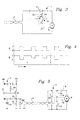
- FIG. 3 there is shown a modification of the system shown in Fig. 1 wherein the switch S1 is replaced by a sliding or rotary contact device 30 having an electrical contact between a rotary arm 32 and a fixed contact 34 extending over a substantial angle of rotation, e.g., 180°, between end points X and Y as determined by the linkage 37 driven by the actuator motor 6.
- the back-EMF of the actuator motor 6 is transmitted over the connecting link 4 for a period of time between the contact positions X and Y of the rotary contact device 30.
- a two-wire multi-position control system having two-wire connecting link 4 between a central station 2 and a remote station 1 wherein the diode 8 at the remote station is not bypassed and is arranged to continuously block the back-EMF of the actuator motor 6.
- a pair of impedances 40,42 are connected in series with respective ones of single-pole,single-throw switches S2,S3.
- Each series combination of impedance and switch is connected in parallel with the series combination of the diode 8 and the motor 6 and across the two wires of the communication link 4.
- the impedances 40,42 form a voltage divider by a series connection with a resistor 44 located in the central station 2.
- the series combination of the resistor 44 and impedances 40,42 is connected across a reference voltage at terminal 46.
- a filter capacitor 48 is also connected to the reference signal terminal 46 and a circuit ground connection.
- a resistor 45 and a diode 49 are connected between the collector of transistor 10 to circuit ground.
- This resistor 45 provides a complete circuit in the event of an open circuit condition when no load is being connected to the connecting link 4.
- the resistor 45 should have a value of at least ten times greater than the impedance of resistors 40,42.
- the diode 49 is added to suppress an overshoot voltage induced during signal switching.
- the output from the central station 1 is obtained from the point B which is the connection between the resistor 44 at the central station 2 and the impedances 40,42 at the remote station 1.
- a source of motor energizing pulses is connected to energizing terminal A to be applied through transistor 10 to the motor 6 in a manner similar to that shown and discussed above with respect to Fig. 1.
- the motor 6 operates the switches S2,S3 through respective linkages 7A,7B.
- the waveforms shown in Fig. 6 illustrate the operation of the system shown in Fig. 5.
- the output from terminal B is dependent on which of the impedances 40,42 are effective in the circuit, i.e., which of the switches S2,S3 is opened or closed.
- the switches S2,S3 are arranged to be alternately operated whereby a closure of one is only effected during a time that the other switch is open.
- the impedances 40,42 are different from each other and each impedance is much greater than the motor impedance.
- the impedance change by selectively closing the switches S2 and S3 is effective to produce respective outputs from point B at the remote station inasmuch as the voltage division effected by the voltage divider including impedances 40,42 is different for each of the impedances 40,42.
- the circuit is able to produce an output at the central station indicative of the position of the actuator output. While the illustration shown in Fig. 5 and waveshape diagram shown in Fig. 6 are directed to a system using two impedances and two switches, it is clear that more impedances of different values and corresponding series switches and motor linkages may be used to provide indications of additional positions of the actuator output at the central station 2.
- Fig. 7 there is shown a modification of the circuit shown in Fig. 2 wherein the combination of the dual impedances 40,42 and switches S2 and S3 is replaced by a variable impedance, e.g., a potentiometer, the fixed impedances 40,42 shown in Fig. 5.
- This rotary or variable impedance device is shown with three positions labeled C, D and E for the arm 52 driven by the actuator motor 6 through the linkage 57.
- a fourth resistor 54 is connected between one end of the variable impedance 50 and the circuit ground to prevent a short circuit from occurring when the variable impedance arm 52 reaches the end of its travel at the location E.
- Fig. 8 is a waveshape diagram illustrating the operation of the circuit shown in Fig.
Landscapes
- Physics & Mathematics (AREA)
- General Physics & Mathematics (AREA)
- Control Of Position Or Direction (AREA)
- Selective Calling Equipment (AREA)
- Arrangements For Transmission Of Measured Signals (AREA)
Abstract
Description
- The present invention relates to two-wire power and position control systems. More specifically, the present invention is directed to a two-wire power and position control system using the two-wire connecting link for transmitting power and data.
- An object of the present invention is to provide a simple and cost effective two-wire power and position control system for transmitting power and data.
- In accomplishing this and other objects, it has been provided, in accordance with the present invention, a novel two-wire power and position control system having a central station, a remote station, a two-wire connecting link between said central station and said remote station, actuator means at said remote station for providing a physical displacement in response to an energizing signal, a data transmitting means at said remote station for transmitting a data signal over said link representative of the physical displacement effected by said actuator, and energizing means at said central station for periodically energizing by an energizing signal applied over said link to said actuator means to periodically effect said physical displacement. In a first form, the remote station utilizes the back-EMF of a permanent magnet DC motor at the remote station as the position indicator. In a second form, the remote station utilizes a change in impedance of a voltage divider to effect a signal at the central station connected to the voltage divider circuitry over the connecting link.
- A better understanding of the present invention may be had when the following detailed description is read in connection with the accompanying drawings, in which:
- Fig. 1 is a schematic illustration of a first novel two-wire communication system,
- Fig. 2 is a waveshape diagram illustrating the operation of the system shown in Fig. 1,
- Fig. 3 is a schematic illustration of a modification of the system shown in Fig. 1,
- Fig. 4 is waveshape diagram illustrating the operation of the modification shown in Fig. 3,
- Fig. 5 is a schematic illustration of a second novel two-wire communication system,
- Fig. 6 is a waveshape diagram illustrating the operation of the system shown in Fig. 5,
- Fig. 7 is schematic illustration of a modification of the system shown in Fig. 5 and
- Fig. 8 is a waveshape diagram illustrating the operation of the modification shown in Fig. 7.
- Referring to Fig. 1 in more detail, there is shown a two-wire power and position control system having a
remote station 1 and acentral station 2 connected by a two-wire connecting link 4. A permanentmagnet DC motor 6 located at theremote station 1 is arranged by means of a mechanical linkage 7 to operate a single-pole,single-throw switch S1 arranged in parallel with adiode 8. Thediode 8 is connected between a remote station end of one of the pair of wires comprising the connecting link 4 and one side of themotor 6. The other side of themotor 6 is connected to the remote station end of the other one of the pair of wires comprising the connecting link 4. At thecentral station 2, the connecting link 4 is connected with an end of one wire connected to a circuit ground and an end of the other wire connected to a collector of atransistor 10. The collector of thetransistor 10 is also connected to the circuit ground through afirst resistor 12. The emitter of thetransistor 10 is connected to a source of supply voltage + V. - A voltage divider comprising a serial combination of a
second resistor 14 and athird resistor 16 is connected between the supply voltage + V the circuit ground connection. Avoltage comparator 16 has a non-inverting input connected to the junction between theseries resistors transistor 10. An output of thevoltage comparator 16 is connected to anoutput terminal 18. A motor energizing input A is connected to a source of energizing pulses generated by a microprocessor (not shown) and is connected to the base of thetransistor 10 to supply a motor energizing signal thereto. - The system shown in Fig. 1 in effective to transmit position data representative signals from the
remote station 1 to thecentral station 2 over the connecting link 4 indicative of the position of the actuator output. The connecting link 4 is also used to transmit the motor energizing pulses initiated at input terminal A to themotor 6. While two-wire communication systems for transmitting data and power between a central station and a remote location are well-known in the art as shown in U.S. Patent No. 3,500,132, such prior art systems have not been capable of transmitting position data as provided by the present invention. The back-EMF generated by themotor 6 between the energizing pulses transmitted over the connecting link 4 is used as a source of actuator output position data signals. The continued presence of such a back-EMF from a DC motor between energizing pulses is well-known in the art, as discussed in U.S. Patent No. 3,411,062. - As shown in Fig. 2, the
actuator motor 6 energizing pulses from the energizing signal input terminal A are applied over the connecting link 4 by means of thetransistor 10. Between the energizing pulses for theactuator motor 6, the effect of the mechanical linkage 7 driven byactuator motor 6 on the switch S1 is communicated back over the connecting link 4. Specifically, the effect of theactuator motor 6 on the switch S1 through the linkage is effective to produce actuator output position data at a preselected position. Thus, as shown in the waveshape diagram B1 with the switch S1 in an open or non-conducting state, thediode 8 is effective to block the back-EMF from theactuator motor 6 whereby no position data signal appears at point B in the central station during the absence of the energizing pulses. Conversely, with the switch S1 closed by theactuator motor 6, thediode 8 is bypassed, and the back-EMF appears at point B in the central station as shown in the waveshape labeled B2. These actuator output position data signals are independent from any load, temperature speed or rotation direction of the actuator motor. Accordingly, the absence or presence of the back-EMF is only controlled by the mechanically operated switch S1 to indicate the position of the actuator, i.e., Whether or not the actuator has reached a position effective to operate the switch S1. - In Fig. 3, there is shown a modification of the system shown in Fig. 1 wherein the switch S1 is replaced by a sliding or
rotary contact device 30 having an electrical contact between arotary arm 32 and afixed contact 34 extending over a substantial angle of rotation, e.g., 180°, between end points X and Y as determined by thelinkage 37 driven by theactuator motor 6. Thus, as shown in the waveshape diagram of Fig. 4, the back-EMF of theactuator motor 6 is transmitted over the connecting link 4 for a period of time between the contact positions X and Y of therotary contact device 30. - In Fig. 5, there is shown a two-wire multi-position control system having two-wire connecting link 4 between a
central station 2 and aremote station 1 wherein thediode 8 at the remote station is not bypassed and is arranged to continuously block the back-EMF of theactuator motor 6. In this arrangement, a pair ofimpedances diode 8 and themotor 6 and across the two wires of the communication link 4. Theimpedances resistor 44 located in thecentral station 2. Specifically, the series combination of theresistor 44 andimpedances terminal 46. Afilter capacitor 48 is also connected to thereference signal terminal 46 and a circuit ground connection. Aresistor 45 and adiode 49 are connected between the collector oftransistor 10 to circuit ground. Thisresistor 45 provides a complete circuit in the event of an open circuit condition when no load is being connected to the connecting link 4. Theresistor 45 should have a value of at least ten times greater than the impedance ofresistors diode 49 is added to suppress an overshoot voltage induced during signal switching. The output from thecentral station 1 is obtained from the point B which is the connection between theresistor 44 at thecentral station 2 and theimpedances remote station 1. A source of motor energizing pulses is connected to energizing terminal A to be applied throughtransistor 10 to themotor 6 in a manner similar to that shown and discussed above with respect to Fig. 1. Themotor 6 operates the switches S2,S3 throughrespective linkages 7A,7B. - The waveforms shown in Fig. 6 illustrate the operation of the system shown in Fig. 5. As may be seen from Fig. 6, the output from terminal B is dependent on which of the
impedances impedances divider including impedances impedances central station 2. - In Fig. 7, there is shown a modification of the circuit shown in Fig. 2 wherein the combination of the
dual impedances impedances arm 52 driven by theactuator motor 6 through thelinkage 57. Afourth resistor 54 is connected between one end of thevariable impedance 50 and the circuit ground to prevent a short circuit from occurring when thevariable impedance arm 52 reaches the end of its travel at the location E. Fig. 8 is a waveshape diagram illustrating the operation of the circuit shown in Fig. 7 wherein the output at the central station at point B is shown for each of the illustrated positions of therotary arm 52. Since the impedance varies as therotary arm 52 is moved by themotor 6, the output from the remote station amplitude signal is also a variable to indicate the corresponding position of the actuator output. - Accordingly, it may be seen that there has been provided, in accordance with the present invention, a simple and cost effective two-wire power and position control system for providing multi-position data signals representative of an actuator output position at a remote station.
Claims (13)
a central station means (2),
a remote station means (1),
a two wire connecting link (4) between said central station and said remote station,
actuator means (6, 7, 7A, 7B, 37, 57) at said remote station for providing a physical displacement in response to an energizing signal,
a data transmitting means (6, 7, 8, 51) at said remote station for transmitting a data signal over said connecting link representative of the physical displacement effected by said actuator means, and
energizing means (A, 10) at said central station for periodically energizing by an energizing signal applied over said connecting link said actuator means to periodically effect said physical displacement.
Applications Claiming Priority (2)
| Application Number | Priority Date | Filing Date | Title |
|---|---|---|---|
| US40168789A | 1989-09-01 | 1989-09-01 | |
| US401687 | 1989-09-01 |
Publications (3)
| Publication Number | Publication Date |
|---|---|
| EP0415655A2 true EP0415655A2 (en) | 1991-03-06 |
| EP0415655A3 EP0415655A3 (en) | 1992-04-01 |
| EP0415655B1 EP0415655B1 (en) | 1996-05-08 |
Family
ID=23588794
Family Applications (1)
| Application Number | Title | Priority Date | Filing Date |
|---|---|---|---|
| EP19900309267 Expired - Lifetime EP0415655B1 (en) | 1989-09-01 | 1990-08-23 | Two-wire power and position control system |
Country Status (4)
| Country | Link |
|---|---|
| EP (1) | EP0415655B1 (en) |
| JP (1) | JPH0398199A (en) |
| CA (1) | CA2018733C (en) |
| DE (1) | DE69026890D1 (en) |
Cited By (4)
| Publication number | Priority date | Publication date | Assignee | Title |
|---|---|---|---|---|
| EP0744679A1 (en) * | 1995-05-22 | 1996-11-27 | Faiveley Transport | Door opening and/or closing electronic control method and means therefor |
| GB2432229A (en) * | 2005-11-09 | 2007-05-16 | Siemens Plc | Communication system between two modules. |
| EP2680431A3 (en) * | 2012-06-29 | 2017-02-15 | Melexis Technologies NV | Method and system for powering and measuring positions of a plurality of DC-motors over a wire interface |
| DE102022119145A1 (en) * | 2022-07-29 | 2024-02-01 | Endress+Hauser Flowtec Ag | Connection circuit for a field device and field device |
Family Cites Families (3)
| Publication number | Priority date | Publication date | Assignee | Title |
|---|---|---|---|---|
| GB1096236A (en) * | 1965-11-12 | 1967-12-20 | English Electric Co Ltd | Improvements in or relating to control systems |
| DK140448B (en) * | 1976-12-17 | 1979-08-27 | Ole Simon Petersen | Remote control mechanism for remote adjustment of a tuning circuit in a radio communication device. |
| GB2187344B (en) * | 1986-02-28 | 1990-01-17 | Plessey Co Plc | Improvements relating to remote control and monitoring of electrical power circuits |
-
1990
- 1990-06-11 CA CA 2018733 patent/CA2018733C/en not_active Expired - Lifetime
- 1990-08-01 JP JP20261090A patent/JPH0398199A/en active Pending
- 1990-08-23 EP EP19900309267 patent/EP0415655B1/en not_active Expired - Lifetime
- 1990-08-23 DE DE69026890T patent/DE69026890D1/en not_active Expired - Lifetime
Cited By (7)
| Publication number | Priority date | Publication date | Assignee | Title |
|---|---|---|---|---|
| EP0744679A1 (en) * | 1995-05-22 | 1996-11-27 | Faiveley Transport | Door opening and/or closing electronic control method and means therefor |
| FR2734598A1 (en) * | 1995-05-22 | 1996-11-29 | Faiveley Transport | METHOD FOR ELECTRONIC CONTROL OF OPENING AND / OR CLOSING A DOOR AND DEVICE FOR IMPLEMENTING IT |
| US5838126A (en) * | 1995-05-22 | 1998-11-17 | Faiveley Transport | Method and apparatus for opening or closing a door by measuring the instantaneous voltage and current in an associated motor |
| GB2432229A (en) * | 2005-11-09 | 2007-05-16 | Siemens Plc | Communication system between two modules. |
| GB2432229B (en) * | 2005-11-09 | 2010-08-18 | Siemens Plc | A Communication System for an Electric Motor Control System |
| EP2680431A3 (en) * | 2012-06-29 | 2017-02-15 | Melexis Technologies NV | Method and system for powering and measuring positions of a plurality of DC-motors over a wire interface |
| DE102022119145A1 (en) * | 2022-07-29 | 2024-02-01 | Endress+Hauser Flowtec Ag | Connection circuit for a field device and field device |
Also Published As
| Publication number | Publication date |
|---|---|
| JPH0398199A (en) | 1991-04-23 |
| CA2018733A1 (en) | 1991-03-01 |
| DE69026890D1 (en) | 1996-06-13 |
| EP0415655B1 (en) | 1996-05-08 |
| CA2018733C (en) | 2000-04-25 |
| EP0415655A3 (en) | 1992-04-01 |
Similar Documents
| Publication | Publication Date | Title |
|---|---|---|
| US4992709A (en) | Switching circuit providing adjustable capacitive series voltage dropping circuit with a fractional horsepower motor | |
| JP2968287B2 (en) | Building management controller | |
| EP0415655B1 (en) | Two-wire power and position control system | |
| CN111511253B (en) | Electromotive furniture drive, piece of furniture and method for detecting the position of an electromotive furniture drive | |
| KR900017838A (en) | Connection system between master device and slave device | |
| KR100187739B1 (en) | Control systems for automotive air conditioning systems | |
| US4422066A (en) | Condition sensor interface means | |
| WO1998019386A1 (en) | Two-wire brushless dc motor control system | |
| JPH01500157A (en) | Circuit arrangement for one or more electrical loads of a motor vehicle | |
| US4045715A (en) | Operator motor control | |
| US4250441A (en) | Servo apparatus with electrical motion limiting | |
| EP3862522B1 (en) | Motor control system for doors and gates | |
| US3922605A (en) | Electrical winch drum rotation indicating system | |
| US4578669A (en) | Remote switch position indicator | |
| JPH10510977A (en) | Circuit device for detecting overload state of adjustment drive unit | |
| US3993977A (en) | Two wire command and monitoring system | |
| EP0422711A1 (en) | Automatic device for powered gate opener with electronic sensing of end of travel | |
| US4017832A (en) | Two wire command and monitoring system | |
| US4754209A (en) | Motor actuator | |
| EP0749883B1 (en) | A control system for railroad track switches | |
| KR20000005471A (en) | Device for operating an adjusting drive | |
| US2788478A (en) | Limit stop control circuit for syncro system | |
| SU590700A1 (en) | System for remote control of a reversible mechanism | |
| US3993979A (en) | Time division-multi-voltage level matrix switching | |
| SU1390767A1 (en) | Device for controlling switch of linear d.c. motor windings |
Legal Events
| Date | Code | Title | Description |
|---|---|---|---|
| PUAI | Public reference made under article 153(3) epc to a published international application that has entered the european phase |
Free format text: ORIGINAL CODE: 0009012 |
|
| AK | Designated contracting states |
Kind code of ref document: A2 Designated state(s): DE FR GB IT NL |
|
| PUAL | Search report despatched |
Free format text: ORIGINAL CODE: 0009013 |
|
| AK | Designated contracting states |
Kind code of ref document: A3 Designated state(s): DE FR GB IT NL |
|
| 17P | Request for examination filed |
Effective date: 19920826 |
|
| 17Q | First examination report despatched |
Effective date: 19931210 |
|
| GRAH | Despatch of communication of intention to grant a patent |
Free format text: ORIGINAL CODE: EPIDOS IGRA |
|
| GRAA | (expected) grant |
Free format text: ORIGINAL CODE: 0009210 |
|
| AK | Designated contracting states |
Kind code of ref document: B1 Designated state(s): DE FR GB IT NL |
|
| PG25 | Lapsed in a contracting state [announced via postgrant information from national office to epo] |
Ref country code: IT Free format text: LAPSE BECAUSE OF FAILURE TO SUBMIT A TRANSLATION OF THE DESCRIPTION OR TO PAY THE FEE WITHIN THE PRE;WARNING: LAPSES OF ITALIAN PATENTS WITH EFFECTIVE DATE BEFORE 2007 MAY HAVE OCCURRED AT ANY TIME BEFORE 2007. THE CORRECT EFFECTIVE DATE MAY BE DIFFERENT FROM THE ONE RECORDED.SCRIBED TIME-LIMIT Effective date: 19960508 Ref country code: FR Effective date: 19960508 Ref country code: NL Free format text: LAPSE BECAUSE OF FAILURE TO SUBMIT A TRANSLATION OF THE DESCRIPTION OR TO PAY THE FEE WITHIN THE PRESCRIBED TIME-LIMIT Effective date: 19960508 |
|
| REF | Corresponds to: |
Ref document number: 69026890 Country of ref document: DE Date of ref document: 19960613 |
|
| PG25 | Lapsed in a contracting state [announced via postgrant information from national office to epo] |
Ref country code: DE Effective date: 19960809 |
|
| NLV1 | Nl: lapsed or annulled due to failure to fulfill the requirements of art. 29p and 29m of the patents act | ||
| EN | Fr: translation not filed | ||
| PLBE | No opposition filed within time limit |
Free format text: ORIGINAL CODE: 0009261 |
|
| STAA | Information on the status of an ep patent application or granted ep patent |
Free format text: STATUS: NO OPPOSITION FILED WITHIN TIME LIMIT |
|
| 26N | No opposition filed | ||
| REG | Reference to a national code |
Ref country code: GB Ref legal event code: IF02 |
|
| PGFP | Annual fee paid to national office [announced via postgrant information from national office to epo] |
Ref country code: GB Payment date: 20070705 Year of fee payment: 18 |
|
| GBPC | Gb: european patent ceased through non-payment of renewal fee |
Effective date: 20080823 |
|
| PG25 | Lapsed in a contracting state [announced via postgrant information from national office to epo] |
Ref country code: GB Free format text: LAPSE BECAUSE OF NON-PAYMENT OF DUE FEES Effective date: 20080823 |