EP0415518A2 - Signal recording apparatus and signal reproducing apparatus - Google Patents
Signal recording apparatus and signal reproducing apparatus Download PDFInfo
- Publication number
- EP0415518A2 EP0415518A2 EP90306407A EP90306407A EP0415518A2 EP 0415518 A2 EP0415518 A2 EP 0415518A2 EP 90306407 A EP90306407 A EP 90306407A EP 90306407 A EP90306407 A EP 90306407A EP 0415518 A2 EP0415518 A2 EP 0415518A2
- Authority
- EP
- European Patent Office
- Prior art keywords
- signal
- pulse
- train
- signals
- tracks
- Prior art date
- Legal status (The legal status is an assumption and is not a legal conclusion. Google has not performed a legal analysis and makes no representation as to the accuracy of the status listed.)
- Withdrawn
Links
Images


Classifications
-
- H—ELECTRICITY
- H04—ELECTRIC COMMUNICATION TECHNIQUE
- H04N—PICTORIAL COMMUNICATION, e.g. TELEVISION
- H04N5/00—Details of television systems
- H04N5/76—Television signal recording
- H04N5/84—Television signal recording using optical recording
- H04N5/85—Television signal recording using optical recording on discs or drums
-
- G—PHYSICS
- G11—INFORMATION STORAGE
- G11B—INFORMATION STORAGE BASED ON RELATIVE MOVEMENT BETWEEN RECORD CARRIER AND TRANSDUCER
- G11B20/00—Signal processing not specific to the method of recording or reproducing; Circuits therefor
- G11B20/10—Digital recording or reproducing
-
- G—PHYSICS
- G11—INFORMATION STORAGE
- G11B—INFORMATION STORAGE BASED ON RELATIVE MOVEMENT BETWEEN RECORD CARRIER AND TRANSDUCER
- G11B7/00—Recording or reproducing by optical means, e.g. recording using a thermal beam of optical radiation by modifying optical properties or the physical structure, reproducing using an optical beam at lower power by sensing optical properties; Record carriers therefor
- G11B7/004—Recording, reproducing or erasing methods; Read, write or erase circuits therefor
- G11B7/0045—Recording
-
- H—ELECTRICITY
- H04—ELECTRIC COMMUNICATION TECHNIQUE
- H04N—PICTORIAL COMMUNICATION, e.g. TELEVISION
- H04N5/00—Details of television systems
- H04N5/76—Television signal recording
- H04N5/91—Television signal processing therefor
- H04N5/917—Television signal processing therefor for bandwidth reduction
- H04N5/919—Television signal processing therefor for bandwidth reduction by dividing samples or signal segments, e.g. television lines, among a plurality of recording channels
Definitions
- the present invention relates to a signal recording apparatus for recording an intelligence signal on an information recording medium and a signal reproducing apparatus for reproducing an intelligence signal from a medium with information recorded.
- An optical disk (including a magneto-optical disk and a phase-change type optical disk) used for optically recording/reproducing information is provided with pits or the like, as the units of information storage domains, arranged thereon in concentric or spiral tracks, with the information recorded in the form of difference in lengths of the pits and intervals therebetween. Reading of the recorded information is accomplished by irradiating the surface having information recorded of the optical disk with a light beam and then by demodulating the reflected light beam, modulated by the presence and absence of the pits, from the recorded surface.
- a light beam in the form of a beam spot whose diameter is virtually equal to the width of the pit, is allowed to irradiate the surface having information recorded such that the light beam spot follows the record track formed of trains of pits and read the recorded information.
- a primary object of the present invention is to provide a signal recording/reproducing apparatus capable of recording a broadband signal keeping the number of revolutions of the disk and the size of the pit virtually at the existing levels.
- the signal recording apparatus of the present invention comprises pulse modulation means for providing a modulated pulse-train signal modulated by an intelligence signal, signal dividing means for generating n sets of divided pulse-train signals, each divided pulse-train signal having its pulse width extending from each of successive n pulse edges of the modulated pulse-train signal to the next but or beyond (n - 1) pulse edges, and signal recording means for recording the divided pulse-train signals in their respective information recording tracks on an information recording medium.
- a signal reproducing apparatus of the present invention comprises signal reading means for reading recorded signals from a plurality of tracks on a recorded medium having an intelligence signal recorded along the plurality of tracks thereby generating read pulse-train signals from their respective tracks, signal processing means performing exclusive OR operation on all the read pulse-train signals thereby obtaining a pulse-train signal, and signal demodulating means for demodulating the pulse-train signal.
- the signal dividing means of the signal recording apparatus divides a demodulated pulse-train signal, which, for example, is FM modulated by an intelligence signal, into n pulse-train signals, and supplies the n divided pulse-train signals, each thereof having its frequency component existing in a lower frequency domain than that of the modulated pulse-train signal, to the signal recording portion.
- the signal recording portion records the n divided pulse-train signals in different tracks on an information recording medium.
- the signal reproducing apparatus reads recorded signals from the plurality of tracks on the medium with information recorded, virtually at the same time, subjects the read pulse-train signals restored from the recorded signals to arithmetic operation so that these are multiplied together and a multiplied pulse-train signal corresponding to the modulated pulse-train signal is obtained, and demodulates this multiplied pulse-train signal to reproduce the original intelligence signal.
- FIG. 1 shows a signal recording system, in which a high definition television signal (hereinafter, to be briefly called "TV signal”) including a luminance signal whose signal bandwidth is 20 MHz is supplied, for example, as the intelligence signal to an FM modulator 1.
- the FM modulator 1 obtains an FM modulated video signal by frequency modulating a carrier signal having a frequency of 30 MHz, for example, by the TV signal a as shown in FIG. 2A, and then, slices the FM modulated video signal at a predetermined level and applies the signal thus obtained to a wave shaping treatment, thereby generating an FM modulated pulse signal b as shown in FIG. 2 B.
- the FM modulated pulse signal is converted by a signal divider 2 into a plurality of pulse-train signals having larger pulse spacings than the FM modulated pulse signal.
- the FM modulated pulse signal b when the FM modulated pulse signal b is divided into two pulse signals, it is, for example, divided, as shown in FIG. 2 C and FIG. 2 D, into one pulse signal c1 having high levels and low levels recurring in response to the rise of the modulated pulse signal b and therefore having the pulse width extending from one pulse edge to the next but or beyond one pulse edge, and the other pulse signal c2 having low levels and high levels recurring in response to the fall of the FM modulated pulse signal b and therefore having the pulse width extending from one pulse edge to the next but one pulse edge.
- the divided pulse signals c1 and c2 are processed to be multiplied together, the resultant pulse signal d becomes equivalent to the FM modulated pulse signal b as shown in FIG. 2 E.
- the signal divider 2 is structured, for example, of frequency dividers formed of flip-flops, logic gates, etc.
- the thus obtained pulse signals c1 and c2, each thereof having the pulse width and pulse spacing virtually twice as large as that of the FM modulated pulse signal b , are supplied to a recording portion 3 for forming the pits in the disk.
- the recording portion 3 is made up of a driving portion for rotating the disk at a fixed speed and an optical system including two light modulators for turning two light beams to be introduced to the recording surface of the disk on and off, independently, and the pulse signals c1 and c2 are respectively supplied to modulating input terminals of the two light modulators.
- TV signals are recorded in two tracks adjoining each other on the disk.
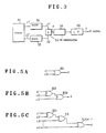
- FIG. 3 shows a signal reproducing apparatus, in which a pickup 31 irradiates two adjoining tracks A and B on the recorded surface of a disk as shown in FIG. 4 with two light beam spots B1 and B2 aligned along the radial direction of the disk and obtains from the reflected light beams two read signals c1′ and c2′ modulated by presence or absence of pits P A and P B .
- the light beam spots B1 and B2 are allowed to make accurate tracking with a predetermined spot diameter by means of focus servo, tracking servo, and so on.
- the read signals c1′ and c2′ are respectively supplied to slice circuits 32 and 33 to be shaped into the form of pulse signal, and thereby, pulse signals c1 and c2 are restored.
- the two pulse signals are subjected to exclusive OR operation in an arithmetic unit 34 whereby the pulse signal e as shorn in FIG. 2 E is obtained. In the operation, a high level signal is output when the two pulse signals are at the same level and a low level signal is output when the two signals are at different levels.
- the pulse signal d has virtually the same waveform as that of the original FM modulated pulse signal b .
- the pulse signal d is demodulated by an FM demodulator 35 into the TV signal a and led out to an output terminal after being passed through an LPF (low pass filter) 36 with a cutoff frequency of 20 MHz, for example, so that only the TV signal band is passed with higher harmonic components eliminated.
- LPF low pass filter
- FIG. 5 A to FIG. 5 C show concrete circuit examples of the arithmetic unit 34 in FIG. 3, in which FIG. 5 A shows the circuit example in the case of two inputs formed of one exclusive OR gate EO, FIG. 5 8 shows the circuit example in the case of three inputs formed of exclusive OR gates EO1 and EO2, and FIG. 5C shows the circuit example in the case of four inputs or above formed of exclusive OR gates EO1 to EO(n - 1).
- an FM modulated pulse signal obtained by FM modulating a carrier signal by an intelligence signal with a great signal bandwidth is divided into two pulse-train signals, whereby signals with a signal frequency bandwidth virtually one half the original bandwidth are obtained, the two pulse-train signals are recorded on the same disk in two different tracks, and, at the time of signal reproduction, the two recorded signals are read from the disk along the two tracks and the read signals are combined so that the FM modulated pulse signal is restored, and the FM modulated pulse signal is FM demodulated and thereby the original intelligence signal is reproduced. Therefore, an intelligence signal having a great signal bandwidth such as a high definition television signal can be recorded on a disk without making the size of the pits recorded on the disk smaller or increasing the number of revolutions of the disk.
- an FM modulated pulse signal is divided into two pulse signals and then these signals are recorded.
- the read signal c2′ the phase of its carrier wave being shifted by 90 degrees, is expressed as v cos ⁇ 2 ⁇ (f C /2)t + ⁇ (t) ⁇ .
- c 1′T ⁇ c 2′T v2(1 + k2) sin ⁇ 2 ⁇ f C /2)t + ⁇ (t) ⁇ ⁇ cos ⁇ 2 ⁇ (f C /2)t + ⁇ (t) ⁇ + kv2 [sin2 ⁇ 2 ⁇ (f C /2)t + ⁇ (t) ⁇ + cos2 ⁇ 2 ⁇ (f C /2)t + ⁇ (t) ⁇ ].
- the output is multiplied by (1 + k2) and a mere offset of kv2 is increased as compared with the values in the state where there is no cross talk.
- the crosstalk can be restricted to the degree as described above as against the case where the two recorded signals are read out of two adjoining tracks and these signals are demodulated as they are.
- like signals to those in FIG. 2 are denoted by corresponding reference characteristics.
- the waveform of the pulse signal c1 rises at the timing of the rise of a first pulse edge of the FM modulated pulse signal b and falls at the timing of the fall of the next but two pulse edge.
- the waveform of the pulse signal c2 rises at the timing of the fall of a second pulse edge of the FM modulated pulse signal b and falls at the timing of the rise of the next but two pulse edge.
- the wave form of the pulse signal c3 rises at the timing of the rise of a third pulse edge of the FM modulated pulse signal b and falls at the timing of the fall of the next but two pulse edge.
- a laser beam emitted from a laser diode 61 is converted to a parallel beam through a collimator lens 62 and, after being passed through beam splitter 63 and a quarter wave (1/4 ⁇ ) plate 64, it is caused by an objective lens 65 to irradiate, as the main beam spot for reading information, the surface with information recorded of an optical disk 6.
- the reflected beam of the irradiating beam from the recorded surface is passed through the objective lens 65 and the quarter wave plate 64 and reflected by the beam splitter 63, and then, it is passed through an optical device for detection 67 to be led onto a photosensor device 68.
- the diameter of the main beam spot in an in-focus state in the present optical system is made large enough to cover a plurality of tracks, as against that in the conventional optical system being virtually equal to the width of the pit, and the photosensor device 68 is formed of a plurality of photosensor elements arranged, for example, two-dimensionally, so that the photosensor device 68 senses light in its field of view uniformly.
- an auxiliary beam spot as the tracking beam spot S T is formed as shown in FIG. 8.
- the tracking beam spot S T is arranged to precede the information reading main beam spot S M in a predetermined relative position therewith.
- the center of the main beam spot S M is kept to follow the target track, i. e., the central track of the n (n ⁇ 2) tracks which the main beam spot S M should cover.
- VHD capacitance type recording disk
- a multichannel CD a magnetic tape
- a card a card
- other analogous recording media having a plurality of tracks.
- a modulated pulse train signal bearing an intelligence signal is divided into n trains of pulses, each pulse thereof having a pulse width extending from one pulse edge to the next but (n - 1) pulse edges, and the divided pulse-train signals are recorded in different tracks, and therefore, an intelligence signal having a great bandwidth such as a high definition television signal can be recorded on the signal recording portion without the need for adapting the signal recording portion for recording of a great bandwidth.
- the signal reproducing apparatus of the present invention it is adapted such that the pulse-train signals read out from a plurality of tracks on the recorded medium together are subjected to exclusive logical operation and then to waveform shaping, and thereafter, a broadband signal is reproduced. Therefore, it is not required to adapt the signal reading system including the pickup for the use of a great bandwidth, and in addition, the effect of crosstalk occurring between adjoining tracks, which is liable to become problem in multitrack reproduction, can be suppressed. In other words, since there is little effect of the crosstalk, it is made possible to make the distance between tracks smaller and, hence, to increase storage capacity of the information recording medium.
Abstract
Description
- The present invention relates to a signal recording apparatus for recording an intelligence signal on an information recording medium and a signal reproducing apparatus for reproducing an intelligence signal from a medium with information recorded.
- An optical disk (including a magneto-optical disk and a phase-change type optical disk) used for optically recording/reproducing information is provided with pits or the like, as the units of information storage domains, arranged thereon in concentric or spiral tracks, with the information recorded in the form of difference in lengths of the pits and intervals therebetween. Reading of the recorded information is accomplished by irradiating the surface having information recorded of the optical disk with a light beam and then by demodulating the reflected light beam, modulated by the presence and absence of the pits, from the recorded surface.
- Conventionally, in such a signal recording/reproducing apparatus, a light beam in the form of a beam spot, whose diameter is virtually equal to the width of the pit, is allowed to irradiate the surface having information recorded such that the light beam spot follows the record track formed of trains of pits and read the recorded information.
- In such a prior art apparatus, when a signal with a very great bandwidth such as that of a high quality television signal is to be recorded, the apparatus will be adapted to support it by having the number of revolutions of the disk increased or the pit size made smaller. However, such arrangements do not work well since there are technical limits in increasing the number of revolutions of the disk or making the size of pit smaller, and in addition, such arrangements increase the cost of manufacture of the recording/reproducing apparatus.
- Accordingly, a primary object of the present invention is to provide a signal recording/reproducing apparatus capable of recording a broadband signal keeping the number of revolutions of the disk and the size of the pit virtually at the existing levels.
- In order to achieve the above mentioned object, the signal recording apparatus of the present invention comprises pulse modulation means for providing a modulated pulse-train signal modulated by an intelligence signal, signal dividing means for generating n sets of divided pulse-train signals, each divided pulse-train signal having its pulse width extending from each of successive n pulse edges of the modulated pulse-train signal to the next but or beyond (n - 1) pulse edges, and signal recording means for recording the divided pulse-train signals in their respective information recording tracks on an information recording medium.
- Further, a signal reproducing apparatus of the present invention comprises signal reading means for reading recorded signals from a plurality of tracks on a recorded medium having an intelligence signal recorded along the plurality of tracks thereby generating read pulse-train signals from their respective tracks, signal processing means performing exclusive OR operation on all the read pulse-train signals thereby obtaining a pulse-train signal, and signal demodulating means for demodulating the pulse-train signal.
- In the described arrangement, the signal dividing means of the signal recording apparatus divides a demodulated pulse-train signal, which, for example, is FM modulated by an intelligence signal, into n pulse-train signals, and supplies the n divided pulse-train signals, each thereof having its frequency component existing in a lower frequency domain than that of the modulated pulse-train signal, to the signal recording portion. The signal recording portion records the n divided pulse-train signals in different tracks on an information recording medium.
- On the other hand, the signal reproducing apparatus reads recorded signals from the plurality of tracks on the medium with information recorded, virtually at the same time, subjects the read pulse-train signals restored from the recorded signals to arithmetic operation so that these are multiplied together and a multiplied pulse-train signal corresponding to the modulated pulse-train signal is obtained, and demodulates this multiplied pulse-train signal to reproduce the original intelligence signal.
- An embodiment of the present invention will now be described by way of example only and with reference to the accompanying drawings, in which :-
- FIG. 1 is a block diagram showing a signal recording apparatus of the present invention;
- FIG. 2 is a diagram for explaining signal waveforms at various points in the signal recording apparatus shown in FIG. 1;
- FIG. 3 is a block diagram showing a signal reproducing apparatus of the present invention;
- FIG. 4 is a drawing for explaining tracks on a medium with information recorded;
- FIG. 5 is a concrete example of an arithmetic circuit in FIG. 3;
- FIG. 6 is a diagram for explaining signal wave forms at various points in the signal reproducing apparatus shown in FIG. 3;
- FIG. 7 is a drawing showing an example structure of a pickup used in a signal reproducing apparatus; and
- FIG. 8 is a drawing for explaining operation of the pickup shown in FIG. 7.
- FIG. 1 shows a signal recording system, in which a high definition television signal (hereinafter, to be briefly called "TV signal") including a luminance signal whose signal bandwidth is 20 MHz is supplied, for example, as the intelligence signal to an
FM modulator 1. TheFM modulator 1 obtains an FM modulated video signal by frequency modulating a carrier signal having a frequency of 30 MHz, for example, by the TV signal a as shown in FIG. 2A, and then, slices the FM modulated video signal at a predetermined level and applies the signal thus obtained to a wave shaping treatment, thereby generating an FM modulated pulse signal b as shown in FIG. 2 B. The FM modulated pulse signal is converted by asignal divider 2 into a plurality of pulse-train signals having larger pulse spacings than the FM modulated pulse signal. - More specifically, when the FM modulated pulse signal b is divided into two pulse signals, it is, for example, divided, as shown in FIG. 2 C and FIG. 2 D, into one pulse signal c₁ having high levels and low levels recurring in response to the rise of the modulated pulse signal b and therefore having the pulse width extending from one pulse edge to the next but or beyond one pulse edge, and the other pulse signal c₂ having low levels and high levels recurring in response to the fall of the FM modulated pulse signal b and therefore having the pulse width extending from one pulse edge to the next but one pulse edge. When the divided pulse signals c₁ and c₂ are processed to be multiplied together, the resultant pulse signal d becomes equivalent to the FM modulated pulse signal b as shown in FIG. 2 E. In the multiplication process, it is adapted such that the result becomes high when the pulse signals c₁ and c₂ are at the same level (including the case where even number of signals are at low level) are multiplied together. The
signal divider 2 is structured, for example, of frequency dividers formed of flip-flops, logic gates, etc. - The thus obtained pulse signals c₁ and c₂, each thereof having the pulse width and pulse spacing virtually twice as large as that of the FM modulated pulse signal b, are supplied to a recording portion 3 for forming the pits in the disk. The recording portion 3 is made up of a driving portion for rotating the disk at a fixed speed and an optical system including two light modulators for turning two light beams to be introduced to the recording surface of the disk on and off, independently, and the pulse signals c₁ and c₂ are respectively supplied to modulating input terminals of the two light modulators. Thus, TV signals are recorded in two tracks adjoining each other on the disk.
- The signal reproducing system will be described with reference to FIG. 3.
- FIG. 3 shows a signal reproducing apparatus, in which a
pickup 31 irradiates two adjoining tracks A and B on the recorded surface of a disk as shown in FIG. 4 with two light beam spots B₁ and B₂ aligned along the radial direction of the disk and obtains from the reflected light beams two read signals c₁′ and c₂′ modulated by presence or absence of pits PA and PB. Though not particularly shown, the light beam spots B₁ and B₂ are allowed to make accurate tracking with a predetermined spot diameter by means of focus servo, tracking servo, and so on. The read signals c₁′ and c₂′ are respectively supplied toslice circuits arithmetic unit 34 whereby the pulse signal e as shorn in FIG. 2 E is obtained. In the operation, a high level signal is output when the two pulse signals are at the same level and a low level signal is output when the two signals are at different levels. The pulse signal d has virtually the same waveform as that of the original FM modulated pulse signal b. The pulse signal d is demodulated by anFM demodulator 35 into the TV signal a and led out to an output terminal after being passed through an LPF (low pass filter) 36 with a cutoff frequency of 20 MHz, for example, so that only the TV signal band is passed with higher harmonic components eliminated. - FIG. 5 A to FIG. 5 C show concrete circuit examples of the
arithmetic unit 34 in FIG. 3, in which FIG. 5 A shows the circuit example in the case of two inputs formed of one exclusive OR gate EO, FIG. 5 8 shows the circuit example in the case of three inputs formed of exclusive OR gates EO1 and EO2, and FIG. 5C shows the circuit example in the case of four inputs or above formed of exclusive OR gates EO1 to EO(n - 1). - In the described manner, an FM modulated pulse signal obtained by FM modulating a carrier signal by an intelligence signal with a great signal bandwidth is divided into two pulse-train signals, whereby signals with a signal frequency bandwidth virtually one half the original bandwidth are obtained, the two pulse-train signals are recorded on the same disk in two different tracks, and, at the time of signal reproduction, the two recorded signals are read from the disk along the two tracks and the read signals are combined so that the FM modulated pulse signal is restored, and the FM modulated pulse signal is FM demodulated and thereby the original intelligence signal is reproduced. Therefore, an intelligence signal having a great signal bandwidth such as a high definition television signal can be recorded on a disk without making the size of the pits recorded on the disk smaller or increasing the number of revolutions of the disk.
- In the above described embodiment, to narrow the frequency band of a signal to be recorded on a disk, an FM modulated pulse signal is divided into two pulse signals and then these signals are recorded. By so doing, a merit is obtained that crosstalk which occurs when adjoining plural tracks are simultaneously read can be reduced. This will be described in the following.
- Representing the frequency of the recorded signal by fS, the carrier frequency of the FM modulator by fC, an amplitude constant by v, and time by t, the read signal c₁′ is expressed as
v sin{2π (fC/2)t + φ (t)},
where φ (t) = sin2π · fS·t. - The read signal c₂′ , the phase of its carrier wave being shifted by 90 degrees, is expressed as
v cos{2π (fC/2)t + φ (t)}. - Supposing now that there is present crosstalk between the read signals c₁′ and c₂′ with a coefficient k (< 1), the read signals c1′T and c2′T including the crosstalk are expressed as
c1′T = v sin{2π (fC/2)t + φ (t)} + k v cos{2π (fC/2)t + φ (t)},
c2′T = v cos{2π (fC/2)t + φ (t)} + k v sin{2π (fC/2)t + φ (t)}. - When the product of the signals c1′T and c2′T is obtained before the FM demodulation is performed in the reproducing system,
c1′T·c2′T
= v²(1 + k²) sin {2π{fC/2)t + φ (t)}
· cos {2π (fC/2)t + φ (t)}
+ kv² [sin²{2π (fC/2)t + φ (t)}
+ cos²{2π (fC/2)t + φ (t)}].
Since sin²α + cos²α = 1,
c1′T·c2′T
= v²(1 + k²) sin{2π (fC/2)t + φ (t)}
· cos{2π (fC/2)t + φ (t)} + kv²
= (1 + k²) c₁′·c₂′ + kv². - Thus, it is clear that the output is multiplied by (1 + k²) and a mere offset of kv² is increased as compared with the values in the state where there is no cross talk. In other words, through the multiplication, the crosstalk can be restricted to the degree as described above as against the case where the two recorded signals are read out of two adjoining tracks and these signals are demodulated as they are.
- FIG. 6 shows a case where an FM modulated pulse signal b is divided into three pulse signals c₁, c₂ and c₃, the pulse signals c₁ to c₃ are respectively recorded in three adjoining different tracks on a disk, and the pulse signals c₁ to c₃ restored on the reproducing side are multiplied together, whereby a pulse signal d (= FM modulated pulse signal b) is obtained. In FIG. 6, like signals to those in FIG. 2 are denoted by corresponding reference characteristics. In the above case, the waveform of the pulse signal c₁ rises at the timing of the rise of a first pulse edge of the FM modulated pulse signal b and falls at the timing of the fall of the next but two pulse edge. The waveform of the pulse signal c₂ rises at the timing of the fall of a second pulse edge of the FM modulated pulse signal b and falls at the timing of the rise of the next but two pulse edge. The wave form of the pulse signal c₃ rises at the timing of the rise of a third pulse edge of the FM modulated pulse signal b and falls at the timing of the fall of the next but two pulse edge.
- By such arrangement, it becomes possible to make the signal bandwidth of the signals c₁ to c₃ still smaller than that of the signals c₁ and c₂ recorded in two tracks as shown in FIG. 1 and FIG. 2.
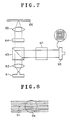
- As described in the foregoing, it is possible to divide a signal to be recorded into two or more signals and record these plural signals in plural tracks, but the pickup for reading the signals from the tracks becomes complex in structure. The present applicant proposed in Japanese Patent Application No. 1-123432 a structure of a pickup suitable for use in such case, outline of which is shown in FIG. 7.
- Referring to FIG. 7, a laser beam emitted from a laser diode 61 is converted to a parallel beam through a
collimator lens 62 and, after being passed throughbeam splitter 63 and a quarter wave (1/4 λ)plate 64, it is caused by anobjective lens 65 to irradiate, as the main beam spot for reading information, the surface with information recorded of an optical disk 6. The reflected beam of the irradiating beam from the recorded surface is passed through theobjective lens 65 and thequarter wave plate 64 and reflected by thebeam splitter 63, and then, it is passed through an optical device fordetection 67 to be led onto aphotosensor device 68. - With described arrangement, the diameter of the main beam spot in an in-focus state in the present optical system is made large enough to cover a plurality of tracks, as against that in the conventional optical system being virtually equal to the width of the pit, and the
photosensor device 68 is formed of a plurality of photosensor elements arranged, for example, two-dimensionally, so that thephotosensor device 68 senses light in its field of view uniformly. - Further, to achieve tracking servo, an auxiliary beam spot as the tracking beam spot ST is formed as shown in FIG. 8. The tracking beam spot ST is arranged to precede the information reading main beam spot SM in a predetermined relative position therewith. By means of a control operation performed based on the beam spot ST, the center of the main beam spot SM is kept to follow the target track, i. e., the central track of the n (n≧ 2) tracks which the main beam spot SM should cover.
- Thus, simultaneous reading of n tracks on the disk, the so-called multitrack reading, is performed.
- Although the embodiment was described above as to its application to an optical recording disk, the present invention can be applied to a capacitance type recording disk (VHD), a multichannel CD, a magnetic tape, a card, and other analogous recording media having a plurality of tracks.
- In the signal recording apparatus of the present invention as described in the foregoing, it is adapted such that a modulated pulse train signal bearing an intelligence signal is divided into n trains of pulses, each pulse thereof having a pulse width extending from one pulse edge to the next but (n - 1) pulse edges, and the divided pulse-train signals are recorded in different tracks, and therefore, an intelligence signal having a great bandwidth such as a high definition television signal can be recorded on the signal recording portion without the need for adapting the signal recording portion for recording of a great bandwidth.
- Further, in the signal reproducing apparatus of the present invention, it is adapted such that the pulse-train signals read out from a plurality of tracks on the recorded medium together are subjected to exclusive logical operation and then to waveform shaping, and thereafter, a broadband signal is reproduced. Therefore, it is not required to adapt the signal reading system including the pickup for the use of a great bandwidth, and in addition, the effect of crosstalk occurring between adjoining tracks, which is liable to become problem in multitrack reproduction, can be suppressed. In other words, since there is little effect of the crosstalk, it is made possible to make the distance between tracks smaller and, hence, to increase storage capacity of the information recording medium. Further, since the signal is subjected to detection after undergoing the arithmetic operation, while demodulation systems in number corresponding to the number of channels required in a frequency division multiplex recording apparatus in the prior art, such an advantage can also be obtained that only one each of filter and TBC (time base correction) circuit is required in the present invention.
Claims (5)
pulse modulation means for providing a modulated pulse-train signal modulated by an intelligence signal;
signal dividing means for generating n sets of divided pulse-train signals, each divided pulse-train signal having its pulse width extending from each of successive n pulse edges of said modulated pulse-train signal to the next but (n - 1) pulse edges; and
signal recording means for recording said divided pulse-train signals in their respective information recording tracks on an information recording medium.
signal reading means for reading recorded signals from a plurality of tracks on an recorded medium having an intelligence signal recorded along the plurality of tracks thereby generating read pulse-train signals from their respective tracks;
signal processing means making exclusive OR operation on all said read pulse-train signals thereby obtaining a pulse-train signal; and
signal demodulating means for demodulating said pulse-train signal.
Applications Claiming Priority (2)
| Application Number | Priority Date | Filing Date | Title |
|---|---|---|---|
| JP22238289A JPH0384772A (en) | 1989-08-28 | 1989-08-28 | Signal recorder and signal reproducing device |
| JP222382/89 | 1989-08-28 |
Publications (2)
| Publication Number | Publication Date |
|---|---|
| EP0415518A2 true EP0415518A2 (en) | 1991-03-06 |
| EP0415518A3 EP0415518A3 (en) | 1991-11-13 |
Family
ID=16781481
Family Applications (1)
| Application Number | Title | Priority Date | Filing Date |
|---|---|---|---|
| EP19900306407 Withdrawn EP0415518A3 (en) | 1989-08-28 | 1990-06-12 | Signal recording apparatus and signal reproducing apparatus |
Country Status (2)
| Country | Link |
|---|---|
| EP (1) | EP0415518A3 (en) |
| JP (1) | JPH0384772A (en) |
Citations (3)
| Publication number | Priority date | Publication date | Assignee | Title |
|---|---|---|---|---|
| US3513266A (en) * | 1967-02-27 | 1970-05-19 | Ibm | Magnetic recording system for wideband signal multiplexing by frequency modulation |
| EP0019378A1 (en) * | 1979-05-14 | 1980-11-26 | Xerox Corporation | A digital optical memory |
| EP0326354A2 (en) * | 1988-01-25 | 1989-08-02 | Olympus Optical Co., Ltd. | Apparatus for reading information out of an optical recording medium |
-
1989
- 1989-08-28 JP JP22238289A patent/JPH0384772A/en active Pending
-
1990
- 1990-06-12 EP EP19900306407 patent/EP0415518A3/en not_active Withdrawn
Patent Citations (3)
| Publication number | Priority date | Publication date | Assignee | Title |
|---|---|---|---|---|
| US3513266A (en) * | 1967-02-27 | 1970-05-19 | Ibm | Magnetic recording system for wideband signal multiplexing by frequency modulation |
| EP0019378A1 (en) * | 1979-05-14 | 1980-11-26 | Xerox Corporation | A digital optical memory |
| EP0326354A2 (en) * | 1988-01-25 | 1989-08-02 | Olympus Optical Co., Ltd. | Apparatus for reading information out of an optical recording medium |
Also Published As
| Publication number | Publication date |
|---|---|
| JPH0384772A (en) | 1991-04-10 |
| EP0415518A3 (en) | 1991-11-13 |
Similar Documents
| Publication | Publication Date | Title |
|---|---|---|
| US3999009A (en) | Apparatus for playing a transparent optically encoded multilayer information carrying disc | |
| US4556967A (en) | Record carrier having an optically readable information structure comprised of information areas of two different phase depths | |
| JPS5935089B2 (en) | Disk-shaped record carrier reading device | |
| GB1529954A (en) | Optically readable records and reading apparatus therefor | |
| US4803677A (en) | Rotary recording medium having a guide track and recording and reproducing apparatus therefor | |
| US5121375A (en) | Information-recorded disk carrying tracking pilot signal and playing apparatus therefor | |
| JPS60234232A (en) | Optical disk and its tracking method | |
| US4006292A (en) | Information recording and reproducing system with plural information tracks within a single groove | |
| US5132957A (en) | Information signal recording and reproducing system capable of recording an information signal on a medium having a limited recording band width | |
| EP0415518A2 (en) | Signal recording apparatus and signal reproducing apparatus | |
| GB2049256A (en) | Information signal recording system | |
| US5841755A (en) | Magnetooptical information recording and reproducing apparatus which reproduces information by detecting only portions of light from a recording medium not shielded by a shielding device | |
| KR19990063012A (en) | Signal Processing Method and Optical Disc Device of Optical Disc | |
| JPH0721865B2 (en) | Optical recording information reader | |
| JPS649662B2 (en) | ||
| US5481369A (en) | Crosstalk detector for optically read signals | |
| JPS6316078B2 (en) | ||
| US4486793A (en) | Reduction of crosstalk effects in modulated audio signals carried in adjacent tracks of recorded media | |
| US5726963A (en) | Information reproduction apparatus including a phase compensation circuit for eliminating the influence of AC-coupling | |
| JPS60677A (en) | Imformation reproducing device | |
| JPH0366735B2 (en) | ||
| JPH0222450B2 (en) | ||
| JPS5938651B2 (en) | Tracking servo device | |
| JPH0498629A (en) | Optical disk and reproducing processing device for read signal from this optical disk | |
| JPS6266425A (en) | Optical information recording and reproducing device |
Legal Events
| Date | Code | Title | Description |
|---|---|---|---|
| PUAI | Public reference made under article 153(3) epc to a published international application that has entered the european phase |
Free format text: ORIGINAL CODE: 0009012 |
|
| AK | Designated contracting states |
Kind code of ref document: A2 Designated state(s): DE FR GB |
|
| PUAL | Search report despatched |
Free format text: ORIGINAL CODE: 0009013 |
|
| AK | Designated contracting states |
Kind code of ref document: A3 Designated state(s): DE FR GB |
|
| 17P | Request for examination filed |
Effective date: 19920120 |
|
| 17Q | First examination report despatched |
Effective date: 19931227 |
|
| STAA | Information on the status of an ep patent application or granted ep patent |
Free format text: STATUS: THE APPLICATION IS DEEMED TO BE WITHDRAWN |
|
| 18D | Application deemed to be withdrawn |
Effective date: 19940507 |