EP0415425A2 - Film loading device - Google Patents
Film loading device Download PDFInfo
- Publication number
- EP0415425A2 EP0415425A2 EP19900116681 EP90116681A EP0415425A2 EP 0415425 A2 EP0415425 A2 EP 0415425A2 EP 19900116681 EP19900116681 EP 19900116681 EP 90116681 A EP90116681 A EP 90116681A EP 0415425 A2 EP0415425 A2 EP 0415425A2
- Authority
- EP
- European Patent Office
- Prior art keywords
- opening
- cassette
- magazine
- cover
- closing
- Prior art date
- Legal status (The legal status is an assumption and is not a legal conclusion. Google has not performed a legal analysis and makes no representation as to the accuracy of the status listed.)
- Granted
Links
Images


Classifications
-
- G—PHYSICS
- G03—PHOTOGRAPHY; CINEMATOGRAPHY; ANALOGOUS TECHNIQUES USING WAVES OTHER THAN OPTICAL WAVES; ELECTROGRAPHY; HOLOGRAPHY
- G03B—APPARATUS OR ARRANGEMENTS FOR TAKING PHOTOGRAPHS OR FOR PROJECTING OR VIEWING THEM; APPARATUS OR ARRANGEMENTS EMPLOYING ANALOGOUS TECHNIQUES USING WAVES OTHER THAN OPTICAL WAVES; ACCESSORIES THEREFOR
- G03B42/00—Obtaining records using waves other than optical waves; Visualisation of such records by using optical means
- G03B42/02—Obtaining records using waves other than optical waves; Visualisation of such records by using optical means using X-rays
- G03B42/04—Holders for X-ray films
- G03B42/045—Holders for X-ray films apparatus for loading or unloading the holders
Definitions
- the present invention relates to a film loading device for feeding a film from a magazine to a cassette in a bright room.
- a magazine which stores a plurality of unexposed photographic films in a light-shielding condition is mounted in a film loading device. After a cassette is mounted in the film loading device, one of the unexposed photographic films is taken out of the magazine and automatically loaded into the cassette. The cassette into which the photographic film has been loaded is then removed from the film loading device for exposure to a radiation image.
- the film loading device has a light-shielding shutter disposed on a film feed path for selectively bringing a magazine chamber and a cassette chamber into comnunication with each other, so that any unexposed films remaining in the magazine can be protected from exposure to undesired light when the cassette is taken out of the film loading device.
- a linear solenoid is employed to actuate the light-shielding shutter.
- the linear solenoid is heated to a considerably high temperature, and might break down owing to an undue temperature rise.
- the linear solenoid is prevented from being subject to unnecessarily high temperatures by a thermostatic switch or the like.
- the linear solenoid which is controlled by the thermostatic switch is however complex in structure, and cannot efficiently load films because of frequently interrupted energization of the linear solenoid.
- a cover of the cassette is opened by an opening and closing mechanism including a suction cup, and after an unexposed photographic film is loaded into the cassette, the cover is closed and a lock pin is actuated and pressed against the cover, which is fixed in position by a lock means in the cassette.
- the opening and closing mechanism for opening and closing the cover and the lock pin for pressing the cover to actuate the lock means are actuated by different actuators.
- the actuators require a large installation space and also need respective dedicated drive sources, with the result that the cost of the film loading device is high.
- a plurality of unexposed photographic films are accommodated in the magazine also in a bright room.
- One known arrangement for loading such plural films into the magazine employs an envelope which contains unexposed photographic films in a light-shielding condition. After the envelope with the films is placed into the magazine, only the envelope is pulled out leaving the films in the magazine.
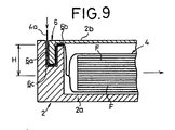
- FIG. 9 of the accompanying drawings shows such a known film loading arrangement.
- an envelope 4 storing unexposed photographic films F in a light-shielding condition is placed in a body 2a of a magazine 2
- a lid 2b is closed and a sealed end 4a of the envelope 4 is hung out of the body 2a through a guide section 6 between the lid 2b and the body 2a.
- the opposite end (not shown) of the envelope 4 is pulled in the direction indicated by the arrow from outside of the magazine 2.
- the envelope 4 is removed out of the magazine 2, leaving the unexposed photographic films F within the magazine 2.
- the guide section 6 comprises a slot-like passage 6a opening out of the magazine 2, a first groove 6b opening into the magazine 2, and a second groove 6c communicating between the passage 6a and the first groove 6b.
- the first groove 6b is spaced relatively widely from the upper surface of the envelope 4. Therefore, the distance H between the first groove 6b and the inner end of the peelable double-layer end portion is relatively large, presenting a large resistance to the movement of the envelope 4 as it is pulled out of the magazine 2. As a result, it is troublesome and time-consuming to load the films F into the magazine 2, and the envelope 4 may be torn or otherwise damaged when pulled out.
- the first groove 6b of the guide section 6 lies substantially parallel to the films F.
- Another object of the present invention is to provide a film loading device comprising a magazine for storing a plurality of unexposed photographic films, a cassette for loading a film which has been taken from the magazine and fed along a feed path, a first chamber for accommodating the magazine therein, a second chamber for accommodating the cassette therein, a light-shielding shutter for selectively bringing the first and second chambers into communication with each other on the feed path, an opening and closing mechanism for opening and closing the cassette, and a shutter actuating mechanism displaceable with the opening and closing mechanism, for engaging the light-shielding shutter to open the light-shielding shutter when the cassette is opened by the opening and closing mechanism.
- Still another object of the present invention is to provide a film loading device wherein the cassette comprises a cassette body for loading the film and a cover openably and closably mounted on the cassette body, the opening and closing mechanism comprising holding means for holding the cover of the cassette in position, and opening and closing means for engaging the cassette body and moving the cassette body to a predetermined angular position with respect to the cover.
- Yet another object of the present invention is to provide a film loading device wherein the holding means comprises a holding member for engaging the cover of the cassette, and a suction cup for sucking the cover.
- Yet still another object of the present invention is to provide a film loading device wherein the opening and closing means comprises a rotative drive source, a link, an opening and closing member which is angularly movable by the rotative drive source through the link, and an engaging finger disposed on the opening and closing member and engageable with the cassette body only, for angularly moving the cassette body through a predetermined angle with respect to the cover.
- the opening and closing means comprises a rotative drive source, a link, an opening and closing member which is angularly movable by the rotative drive source through the link, and an engaging finger disposed on the opening and closing member and engageable with the cassette body only, for angularly moving the cassette body through a predetermined angle with respect to the cover.
- a further object of the present invention is to provide a film loading device wherein the shutter actuating mechanism comprises a protruding portion disposed on the opening and closing mechanism and engageable with the shutter, and a resilient member engaging the shutter, the arrangement being such that when the opening and closing mechanism is displaced to close the cassette, the protruding portion disengages from the shutter to allow the shutter to be closed under the resiliency of the resilient member.
- a still further object of the present invention is to provide a film loading device wherein the magazine comprises a magazine body for placing an envelope containing the unexposed photographic films, and a lid openably and closably mounted on the magazine body, the magazine body and the lid jointly defining a guide section for guiding the envelope when the envelope is withdrawn from the magazine, the guide section having a groove positioned away from a surface of the package near the lid toward the magazine body and extending across the plane of the films.
- a yet further object of the present invention is to provide a film loading device wherein the groove is substantially symmetrical in shape from a center thereof toward opposite ends thereof along a direction transverse to the direction in which the envelope is withdrawn from the magazine.
- a further object of the present invention is to provide a film loading device wherein the magazine body and the lid define therebetween a film withdrawal slot for allowing an end of the envelope to pass therethrough out of the magazine across the plane of the films.
- a film loading device comprising opening and closing means for automatically opening and closing a cassette which comprises a cassette body for loading an unexposed photographic film, and a cover openably and closably mounted on the cassette body, the opening and closing means including lock means for locking the cover to the cassette body, the opening and closing means comprising holding means for holding the cover or the cassette body in position, opening and closing means for engaging and moving the cassette body or the cover to a predetermined angular position with respect to the cover or the cassette body, and pressing means displaceable with the opening and closing means, for pressing the cassette body or the cover and actuating the lock means to securely fasten the cover and the cassette body to each other, when the cassette is closed by the opening and closing means.
- Another object of the present invention is to provide the film loading device wherein the holding means comprises a holding member for engaging the cover of the cassette, and a suction cup for sucking the cover.
- Still another object of the present invention is to provide the film loading device wherein the opening and closing means comprises a rotative drive source, a link, an opening and closing member which is angularly movable by the rotative drive source through the link, and an engaging finger disposed on the opening and closing member and engageable with the cassette body only, for angularly moving the cassette body through a predetermined angle with respect to the cover, the pressing means comprising means for pressing the cassette case to cause the lock means to fasten the cassette body and the cover to each other when the cassette case is angularly moved toward the cover.
- Yet another object of the present invention is to provide the film loading device wherein the pressing means comprises a pressing member disposed on the opening and closing member, and a resilient member mounted on the link, for resiliently pressing the pressing member against the cassette body.
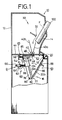
- FIG. 1 shows a film loading device 10 according to the present invention.
- the film loading device 10 has a housing 12 which includes a magazine loading unit 14 in one upper side thereof and a cassette loading unit 16 disposed below the magazine loading unit 14.
- the magazine loading unit 14 holds a magazine 100 which contains a stack of unexposed photographic films F
- the cassette loading unit 16 holds a cassette 22 which has been inserted from an opening 20 defined in the housing 12 through a shutter 19 which can selectively be opened and closed.
- a sheet feed mechanism 30 is disposed in an upper portion of the housing 12 near the magazine 100 held in the magazine loading unit 14.
- the sheet feed mechanism 30 includes a plurality of suction cups 32 connected to a vacuum source (not shown).
- the suction cups 32 are movable along a predetermined path to impart a swinging action to the films F when they are to be taken one by one from the magazine 100.
- a pair of guide plates 40a, 40b and a pair of feed rollers 42 are disposed below the sheet feed mechanism 30.
- the feed rollers 42 are positioned near and above a horizontal partition 44 in the housing 12.
- the feed rollers 42 serve to feed a film F along a feed path into a film inser tion slot 46 defined in the partition 44 and extending in a direction normal to the sheet of FIG. 1.
- a light-shielding shutter 48 is mounted on the lower surface of the partition 44 and guided by the guide plates 40a, 40b for back and forth movement across the film insertion slot 46 in the directions indicated by the arrows (FIG. 2).
- the shutter 48 is normally urged to move to the right in FIG. 1 by a spring 56.
- the shutter 48 has a slot 52 similar to the film insertion slot 46 and a downwardly bent engaging member 54 against which the spring 56 is held.
- a cassette opening and closing mechanism 60 is disposed below the shutter 48.
- the cassette opening and closing mechanism 60 includes an opening and closing mechanism 61 and a holding mechanism 63.
- the opening and closing mechanism 61 includes a rotative drive source 62 with one end of a link 64 mounted on its rotatable shaft. The other end of the link 64 is coupled to one end of an arm 66, the other end of which is joined to a slide plate 68 through a rod 70 and a coil spring 72.
- the slide plate 68 has one end coupled to an opening and closing member 78.
- the opening and closing member 78 is swingably supported on a support pin 80 at its lower end.
- the opening and closing member 78 also has a pair of stoppers 82 on the lower end for holding the cassette 22, and a pair of bent engaging fingers 84 on its upper portion.
- the opening and closing member 78 includes projecting portions 85 upward of the respective engaging fingers 84.
- the projecting portions 85 and the spring 56 which engages the shutter 48 jointly serve as a shutter actuating mechanism 89.
- the opening and closing member 78 has a presser 87 disposed inwardly of the engaging fingers 84.
- the presser 87 and the coil spring 72 jointly constitute a pressing mechanism 91.
- the holding mechanism 63 comprises a pair of cassette holders 86 facing the opening and closing member 78 and obliquely fixed to the cassette loading unit 16, and a pair of suction cups 88 connected to a vacuum source (not shown) and positioned between cassette holders 86.
- the cassette 22 which is to be loaded into the cassette loading unit 16 has a cassette body 22a for loading a single film F and a cover 22b which is openable and closable with respect to the cassette body 22a.
- the cover 22b is shorter than the cassette body 22a in the direction normal to the sheet of FIG. 1.
- the engaging fingers 84 of the opening and closing member 78 can hold the cassette body 22a out of physical interference with the cover 22b.
- the cassette 22 has a known lock means 92 for locking the cover 22b on the cassette body 22a.
- the lock means 92 comprises a pair of stoppers 94a, 94b disposed in the cover 22b and resiliently retractably projecting from a free end of the cover 22b. When the cover 22b is closed, the stoppers 94a, 94b are inserted respectively in holes (not shown) defined in the cassette body 22a.
- the magazine 100 comprises a magazine body 112 and a lid 114 openably and closably mounted on the magazine body 112, the magazine body 112 having a handle 116 on one end thereof.
- the magazine body 112 defines therein a space 118 for placing an envelope 4.
- a pair of parallel light-shielding rollers 119a, 119b is disposed in the space 118 at one end thereof near the handle 116.
- Another roller 119c is mounted on the lid 114 at one end thereof for rolling engagement with the rollers 119a, 119b.
- the magazine body 112 and the lid 114 jointly define an envelope withdrawal slot or opening 120 above the rollers 119a, 119b, 119c for withdrawing an end 4b of the envelope 4 therethrough.
- the envelope withdrawal slot 120 is defined between an upper edge of the magazine body 112 and an edge of the lid 114, and extends linearly in a direction normal to the direction (indicated by the arrow X) in which the envelope 4 is pulled out of the magazine 100.
- the other end of the magazine body 112 has first and second protruding portions 122, 124.
- the lid 114 also has third and fourth protruding portions 126, 128 coacting respectively with the first and second protruding portions 122, 124.
- the first through fourth protruding portions 122, 124, 126, 128 jointly serve as a guide section 121.
- the first protruding portion 122 and the third protruding portion 126 define therebetween a first groove 130 positioned lower than the upper surface of the envelope 4 (i.e., the surface near the lid 114).
- the first groove 130 has two spaced side groove segments 130a, 130b extending parallel to the films F and having the same length as each other.
- the groove segments 130a, 130b have respective ends communicating with groove segments 130c, 130d, respectively, which are inclined to a direction parallel to the films F at a certain angle smaller than 90°.
- the first groove 130 also has a central groove segment 130e whose opposite ends communicate with inner ends of the groove segments 130c, 130d, respectively, the groove segment 130e extending parallel to the films F.
- the groove segments 130c, 130d are formed which extend from the central portion to the opposite end portions of the first groove 130, the groove segments 130c, 130d being substantially symmetric in shape and not parallel to the films F.
- the second and fourth protruding portions 124, 128 are substantially complementary in shape to the first and third protruding portions 122, 126, respectively, and define therebetween a second groove 131 which is positioned in the magazine body 112 and contiguous to the first groove 130 through steps.
- the lid 114 is smaller than the magazine body 112.
- the other edge of the lid 114 and the other upper edge of the magazine body 112 jointly define therebetween a passage 136 which communicates with the first and second grooves 130, 131.
- the passage 136 allows a sealed end 4a of the envelope 4 to be hung out of the magazine 100.
- the lid 114 has an opening 138 defined adjacent to the guide section 121, for taking out a film F from within the magazine body 112 therethrough.
- the opening 138 can selectively be opened and closed by a shutter 140.
- the film loading device according to the present invention is basically constructed as described above. Operation of the film loading device will now be described below.
- the lid 114 is opened and the envelope 4 is placed into the chamber 118 in the magazine body 112.
- the envelope 4 stores therein a plurality of unexposed photographic films F in a light-shielding condition which are held together by a channel-shaped pad A of cardboard.
- the peelable double-layer end portion contiguous to the end 4a of the envelope 4 is positioned on the first and second protruding portions 122, 124 and extends through the external passage 136.
- the other end portion contiguous to the other end 4b of the envelope 4 extends along the rollers 119a, 119b, 119c, with the end 4b projecting out of the slot 120.
- the lid 114 is closed to shield the chamber 118 from extraneous light.
- the end portion leading to the end 4a of the envelope 4 is held in the passage 136 and the grooves 130, 131 of the guide section 121, whereas the other end portion leading to the other end 4b is gripped by the rollers 119a, 119b, 119c.
- the sealed end 4a of the envelope 4 is cut off by a cutter (not shown), and thereafter the other end 4b is pulled in the direction indicated by the arrow X (FiG. 5) to withdraw the envelope 4 out of the magazine 100 from the slot 120 while the envelope 4 is being squeezed by the rollers 119a through 119c, leaving the films F together with the cardboard A in the space 118.
- the first groove 130 of the guide section 121 is defined in a position lower than the upper surface of the envelope 4. Therefore, the resistance applied to the envelope 4 as it is drawn out of the magazine 100 is greatly reduced, so that the envelope 4 can easily be removed from the magazine 100 without damage.
- the first groove 130 is substantially symmetrical in shape from its center toward the opposite ends as shown in FIG. 6, the end 4a of the envelope 4 is pulled substantially uniformly along its length.
- the slot 120 for withdrawing the end 4b of the envelope 4 out of the magazine 100 is defined in the upper portion of the magazine body 112. Therefore, the end 4b can easily be pulled in the direction indicated by the arrow X by the user while gripping the handle 116. Accordingly, the envelope 4 can reliably be removed from the magazine 100.
- the magazine 100 is loaded in the magazine loading unit 14 of the film loading device 10.
- the sheet feed mechanism 30 is actuated after the shutter 140 of the magazine 100 is opened.
- the suction cup 32 sucks and holds the uppermost film F in the magazine 100, giving a swinging action to the film F, and then the film F is supplied to the guide plates 40a, 40b and the feed roller pair 42 (see FIG. 1).
- the magazine 100 is inclined with respect to the vertical direction with the guide section 121 down.
- the first groove 130 of the guide section 121 is composed of the groove segments 130c, 130d extending across the plane of the film F (see FIG. 6). Therefore, even if another film F adjacent to the film F which has directly been sucked up by the suction cup 32 is accidentally displaced toward the first groove 130, the film F is prevented from falling into the first groove 130. Therefore, the sheet feed mechanism 30 can reliably and effectively feed the film F toward the cassette 22 without a feed failure.
- the cassette 22 in the cassette loading unit 16 has been opened by the cassette opening and closing mechanism 60. More specifically, the cover 22b of the cassette 22 has been positioned with respect to the cassette holders 86 by being sucked by the suction cups 88 of the holding mechanism 63, and the engaging fingers 84 of the opening and closing mechanism 61 have engaged the cassette body 22a of the cassette 22.
- the rotative drive source 62 is actuated to rotate the link 64, causing the arm 66 to pull the slide plate 68 for thereby angularly moving the opening and closing member 78 together with the cassette body 22a away from the cover 22b.
- the opening and closing member 78 swings about the support pin 80, the projecting portions 85 integral with the engaging fingers 84 engage the engaging member 54 of the shutter 48, and move the engaging member 54 in the direction indicated by the arrow in FIG. 7(a) against the bias of the spring 56.
- the slot 52 of the shutter 48 is held in registry with the film insertion slot 46 in the partition 44.
- the film F is fed by the feed roller pair 42 to fall into a position between the cassette body 22a and the cover 22b.
- the continued energization of the rotative drive source 62 enables the arm 66 to turn the cassette body 22a toward the cover 22b, thus closing the cassette 22.
- the shutter 48 is displaced in the direction indicated by the arrow (FIG. 7(b)) under the bias of the spring 56.
- the presser 87 of the opening and closing member 78 is pressed against the cassette body 22a. Since the slide plate 68 is coupled to the arm 68 through the rod 70 and the coil spring 72, the presser 87 resiliently presses the cassette body 22a under the bias of the coil spring 72 (see FIG. 7(c)).
- the stoppers 94a, 94b in the cover 22b are inserted into the respective holes in the cassette body 22a, and the cassette body 22a and the cover 22b are locked together by the lock means 92.
- the film F is now loaded in the cassette 22 in a light-shielding condition, and the shutter 48 is displaced to the right (FIG. 1) under the resiliency of the spring 56.
- the suction cups 88 are now inactivated and the shutter 19 is opened to allow the cassette 22 to be removed from the cassette loading unit 16. At this time, no undesirable light enters the upper chamber in the housing 12, in which the magazine 100 is loaded.
- the cassette 22 with the unexposed film F loaded therein is sent into a radiation imaging apparatus (not shown), in which the film F is exposed to the radiation image of an object such as a human body.
- the opening and closing member 78 of the cassette opening and closing mechanism 60 which swings the cassette body 22a to open and close the cassette 22 has the projecting portions 85 of the shutter actuating mechanism 89. Therefore, simply by angularly moving the opening and closing member 78 with the rotative drive source 62, the projecting portions 85 engage the engaging member 54 of the shutter 48 to bring the slot 52 of the shutter 48 into communication with the film insertion slot 46.
- the shutter 48 closes the film insertion slot 46 under the resilient forces of the spring 56 of the shutter actuating mechanism 89. Therefore, it is not necessary to employ a dedicated drive source such as a linear solenoid for opening and closing the shutter 48. Instead, the shutter actuating mechanism 89 is simple in construction, small in size, and can be manufactured economically. Because no linear solenoid is employed, the shutter actuating mechanism 89 is not subject to undue temperature rises. As a consequence, the film loading process can efficiently be performed without interruption.
- the presser 87 of the pressing mechanism 91 is disposed on the opening and closing member 78, so that the cassette body 22a can be opened and closed and the cassette body 22a and the cover 22b can be securely fastened to each other, continuously and reliably by the actuation of the single rotative drive source 62.
- the cassette opening and closing mechanism 60 is much smaller and can be manufactured much more economically than would be if the cassette body 22a were opened and closed and the cassette body 22a and the cover 22b were securely fastened to each other by respective drive sources.
- a magazine 200 according to a second embodiment of the present invention will be described below with reference to FIG. 8.
- Those parts shown in FIG. 8 which are identical to those of the magazine 100 according to the first embodiment are denoted by reference numerals which are the sum of the corresponding reference numerals and 100, and will not be described in detail.
- the magazine 200 has a passage 236 contiguous to grooves 230, 231 in a guide section 221 and a film withdrawal slot 220, the passage 236 and the film withdrawal slot 220 lying parallel to the films F stored in the magazine 200.
- the magazine 200 includes a magazine body 212 which supports a squeezing roller 240a and light-shielding rollers 242a, 242b near the slot 220, and a lid 214 which supports a squeezing roller 240b and a light-shielding roller 242c.
- the light-shielding rollers 242a, 242b, 242c are surrounded by a light-shielding partition 244.
- Films F are loaded into the magazine 200 in substantially the same manner as they are loaded into the magazine 100 according to the first embodiment.
- the envelope 4 can smoothly be removed from the magazine 200 in the same manner as with the first embodiment.
- the guide sections 121 and 221 have the straight grooves 130, 131 and 230, 231, respectively.
- the guide sections may have curved grooves or otherwise shaped grooves insofar as they have groove segments which extend across the plane of the film F.
- the shutter actuating mechanism associated with the opening and closing mechanism actuates the shutter to bring the chamber in which the magazine is positioned into communication with the chamber in which the cassette is positioned. Accordingly, no dedicated drive source is necessary for actuating the shutter, and the shutter actuating mechanism is simple in structure. The film loading device can thus be manufactured inexpensively.
- the pressing mechanism associated with the opening and closing mechanism When the opening and closing mechanism is displaced to close the cassette, the pressing mechanism associated with the opening and closing mechanism also actuates the lock of the cassette, locking the cassette in position. Therefore, any dedicated drive source for actuating the pressing mechanism is not necessary, so that the cassette opening and closing mechanism is relatively small in size and low in cost.
- the grooves in the guide section for guiding the envelope end portion when the envelope is to be removed from the magazine are positioned lower than the height of the package in the magazine. Consequently, the resistance which is presented to the envelope as it is pulled out of the magazine is reduced, allowing the envelope to be removed easily and reliably.
- the groove opening into the magazine chamber extends across the plane of the film, when films are fed one by one from the magazine which is obliquely mounted in the magazine loading unit, an adjacent film next to the film to be fed from the magazine is prevented from falling into the groove. Therefore, the films can efficiently be fed one by one reliably from the magazine.
Abstract
Description
- The present invention relates to a film loading device for feeding a film from a magazine to a cassette in a bright room.
- When a photographic film is to be exposed to the radiation image of an object such as a human body, for example, such a photographic film is supplied from a cassette. In recent years, there has been used an arrangement in which a photographic film is loaded into a cassette in a bright room.
- More specifically, a magazine which stores a plurality of unexposed photographic films in a light-shielding condition is mounted in a film loading device. After a cassette is mounted in the film loading device, one of the unexposed photographic films is taken out of the magazine and automatically loaded into the cassette. The cassette into which the photographic film has been loaded is then removed from the film loading device for exposure to a radiation image.
- The film loading device has a light-shielding shutter disposed on a film feed path for selectively bringing a magazine chamber and a cassette chamber into comnunication with each other, so that any unexposed films remaining in the magazine can be protected from exposure to undesired light when the cassette is taken out of the film loading device.
- Generally, a linear solenoid is employed to actuate the light-shielding shutter. When films are loaded into the cassette relatively frequently, the linear solenoid is heated to a considerably high temperature, and might break down owing to an undue temperature rise. Usually, the linear solenoid is prevented from being subject to unnecessarily high temperatures by a thermostatic switch or the like. The linear solenoid which is controlled by the thermostatic switch is however complex in structure, and cannot efficiently load films because of frequently interrupted energization of the linear solenoid.
- In the film loading device, a cover of the cassette is opened by an opening and closing mechanism including a suction cup, and after an unexposed photographic film is loaded into the cassette, the cover is closed and a lock pin is actuated and pressed against the cover, which is fixed in position by a lock means in the cassette.
- The opening and closing mechanism for opening and closing the cover and the lock pin for pressing the cover to actuate the lock means are actuated by different actuators. The actuators require a large installation space and also need respective dedicated drive sources, with the result that the cost of the film loading device is high.
- A plurality of unexposed photographic films are accommodated in the magazine also in a bright room. One known arrangement for loading such plural films into the magazine employs an envelope which contains unexposed photographic films in a light-shielding condition. After the envelope with the films is placed into the magazine, only the envelope is pulled out leaving the films in the magazine.
- FIG. 9 of the accompanying drawings shows such a known film loading arrangement. When an
envelope 4 storing unexposed photographic films F in a light-shielding condition is placed in abody 2a of a magazine 2, alid 2b is closed and a sealedend 4a of theenvelope 4 is hung out of thebody 2a through a guide section 6 between thelid 2b and thebody 2a. After theend 4a of theenvelope 4 is cut off by a cutter (not shown), the opposite end (not shown) of theenvelope 4 is pulled in the direction indicated by the arrow from outside of the magazine 2. Now, only theenvelope 4 is removed out of the magazine 2, leaving the unexposed photographic films F within the magazine 2. When theenvelope 4 is pulled out, its peelable double-layer end portion is guided by and passes through the guide section 6. The guide section 6 comprises a slot-like passage 6a opening out of the magazine 2, a first groove 6b opening into the magazine 2, and asecond groove 6c communicating between thepassage 6a and the first groove 6b. - With the illustrated arrangement, the first groove 6b is spaced relatively widely from the upper surface of the
envelope 4. Therefore, the distance H between the first groove 6b and the inner end of the peelable double-layer end portion is relatively large, presenting a large resistance to the movement of theenvelope 4 as it is pulled out of the magazine 2. As a result, it is troublesome and time-consuming to load the films F into the magazine 2, and theenvelope 4 may be torn or otherwise damaged when pulled out. - The first groove 6b of the guide section 6 lies substantially parallel to the films F. After the magazine 2 is obliquely mounted in the film loading device, when the films F are to be fed one by one into the cassette, an adjacent film F next to the film F which is to be taken out of the magazine 2 at this time tends to fall into the first groove 6b. When this happens, the films F cannot be fed from the magazine 2. Accordingly, it is not possible to supply the films F efficiently to the cassette.
- It is a major object of the present invention to provide a film loading device which includes a light-shielding shutter that can be actuated with a simple arrangement disposed on a film feed path for selectively bringing a magazine chamber and a cassette chamber into communication with each other, and which can load films highly efficiently.
- Another object of the present invention is to provide a film loading device comprising a magazine for storing a plurality of unexposed photographic films, a cassette for loading a film which has been taken from the magazine and fed along a feed path, a first chamber for accommodating the magazine therein, a second chamber for accommodating the cassette therein, a light-shielding shutter for selectively bringing the first and second chambers into communication with each other on the feed path, an opening and closing mechanism for opening and closing the cassette, and a shutter actuating mechanism displaceable with the opening and closing mechanism, for engaging the light-shielding shutter to open the light-shielding shutter when the cassette is opened by the opening and closing mechanism.
- Still another object of the present invention is to provide a film loading device wherein the cassette comprises a cassette body for loading the film and a cover openably and closably mounted on the cassette body, the opening and closing mechanism comprising holding means for holding the cover of the cassette in position, and opening and closing means for engaging the cassette body and moving the cassette body to a predetermined angular position with respect to the cover.
- Yet another object of the present invention is to provide a film loading device wherein the holding means comprises a holding member for engaging the cover of the cassette, and a suction cup for sucking the cover.
- Yet still another object of the present invention is to provide a film loading device wherein the opening and closing means comprises a rotative drive source, a link, an opening and closing member which is angularly movable by the rotative drive source through the link, and an engaging finger disposed on the opening and closing member and engageable with the cassette body only, for angularly moving the cassette body through a predetermined angle with respect to the cover.
- A further object of the present invention is to provide a film loading device wherein the shutter actuating mechanism comprises a protruding portion disposed on the opening and closing mechanism and engageable with the shutter, and a resilient member engaging the shutter, the arrangement being such that when the opening and closing mechanism is displaced to close the cassette, the protruding portion disengages from the shutter to allow the shutter to be closed under the resiliency of the resilient member.
- A still further object of the present invention is to provide a film loading device wherein the magazine comprises a magazine body for placing an envelope containing the unexposed photographic films, and a lid openably and closably mounted on the magazine body, the magazine body and the lid jointly defining a guide section for guiding the envelope when the envelope is withdrawn from the magazine, the guide section having a groove positioned away from a surface of the package near the lid toward the magazine body and extending across the plane of the films.
- A yet further object of the present invention is to provide a film loading device wherein the groove is substantially symmetrical in shape from a center thereof toward opposite ends thereof along a direction transverse to the direction in which the envelope is withdrawn from the magazine.
- A further object of the present invention is to provide a film loading device wherein the magazine body and the lid define therebetween a film withdrawal slot for allowing an end of the envelope to pass therethrough out of the magazine across the plane of the films.
- It is also an object of the present invention to provide a film loading device comprising opening and closing means for automatically opening and closing a cassette which comprises a cassette body for loading an unexposed photographic film, and a cover openably and closably mounted on the cassette body, the opening and closing means including lock means for locking the cover to the cassette body, the opening and closing means comprising holding means for holding the cover or the cassette body in position, opening and closing means for engaging and moving the cassette body or the cover to a predetermined angular position with respect to the cover or the cassette body, and pressing means displaceable with the opening and closing means, for pressing the cassette body or the cover and actuating the lock means to securely fasten the cover and the cassette body to each other, when the cassette is closed by the opening and closing means.
- Another object of the present invention is to provide the film loading device wherein the holding means comprises a holding member for engaging the cover of the cassette, and a suction cup for sucking the cover.
- Still another object of the present invention is to provide the film loading device wherein the opening and closing means comprises a rotative drive source, a link, an opening and closing member which is angularly movable by the rotative drive source through the link, and an engaging finger disposed on the opening and closing member and engageable with the cassette body only, for angularly moving the cassette body through a predetermined angle with respect to the cover, the pressing means comprising means for pressing the cassette case to cause the lock means to fasten the cassette body and the cover to each other when the cassette case is angularly moved toward the cover.
- Yet another object of the present invention is to provide the film loading device wherein the pressing means comprises a pressing member disposed on the opening and closing member, and a resilient member mounted on the link, for resiliently pressing the pressing member against the cassette body.
- The above and other objects, features and advantages of the present invention will become more apparent from the following description when taken in conjunction with the accompanying drawings in which preferred embodiments of the present invention are shown by way of illustrative example.
-
- FIG. 1 is a schematic vertical cross-sectional view of a film loading device according to the present invention;
- FIG. 2 is a schematic perspective view of the film loading device shown in FIG. 1;
- FIG. 3 is a perspective view of a cassette opening/closing mechanism of the film loading device shown in FIG. 1;
- FIG. 4 is a perspective view of a magazine according to a first embodiment of the present invention, of the film loading device;
- FIG. 5 is a vertical cross-sectional view of the magazine shown in FIG. 4;
- FIG. 6 is a fragmentary elevational view of a guide section in the magazine shown in FIG. 4;
- FIGS. 7(a), 7(b), and 7(c) are fragmentary elevational views, partly in cross section, showing the manner in which a cassette is opened and closed and a shutter is opened and closed;
- FIG. 8 is a vertical cross-sectional view of a magazine according to a second embodiment of the present invention; and
- FIG. 9 is a fragmentary vertical cross-sectional view of a conventional magazine.
- FIG. 1 shows a
film loading device 10 according to the present invention. Thefilm loading device 10 has ahousing 12 which includes amagazine loading unit 14 in one upper side thereof and acassette loading unit 16 disposed below themagazine loading unit 14. Themagazine loading unit 14 holds amagazine 100 which contains a stack of unexposed photographic films F, and thecassette loading unit 16 holds acassette 22 which has been inserted from anopening 20 defined in thehousing 12 through ashutter 19 which can selectively be opened and closed. - A
sheet feed mechanism 30 is disposed in an upper portion of thehousing 12 near themagazine 100 held in themagazine loading unit 14. Thesheet feed mechanism 30 includes a plurality ofsuction cups 32 connected to a vacuum source (not shown). Thesuction cups 32 are movable along a predetermined path to impart a swinging action to the films F when they are to be taken one by one from themagazine 100. - A pair of
guide plates feed rollers 42 are disposed below thesheet feed mechanism 30. Thefeed rollers 42 are positioned near and above ahorizontal partition 44 in thehousing 12. Thefeed rollers 42 serve to feed a film F along a feed path into a filminser tion slot 46 defined in thepartition 44 and extending in a direction normal to the sheet of FIG. 1. - As shown in FIGS. 1 and 2, a light-shielding
shutter 48 is mounted on the lower surface of thepartition 44 and guided by theguide plates film insertion slot 46 in the directions indicated by the arrows (FIG. 2). Theshutter 48 is normally urged to move to the right in FIG. 1 by aspring 56. Theshutter 48 has aslot 52 similar to thefilm insertion slot 46 and a downwardly bent engagingmember 54 against which thespring 56 is held. - A cassette opening and
closing mechanism 60 is disposed below theshutter 48. As shown in FIGS. 2 and 3, the cassette opening andclosing mechanism 60 includes an opening andclosing mechanism 61 and aholding mechanism 63. The opening andclosing mechanism 61 includes arotative drive source 62 with one end of alink 64 mounted on its rotatable shaft. The other end of thelink 64 is coupled to one end of anarm 66, the other end of which is joined to aslide plate 68 through arod 70 and acoil spring 72. Theslide plate 68 has one end coupled to an opening and closingmember 78. The opening and closingmember 78 is swingably supported on asupport pin 80 at its lower end. The opening and closingmember 78 also has a pair ofstoppers 82 on the lower end for holding thecassette 22, and a pair of bentengaging fingers 84 on its upper portion. The opening and closingmember 78 includes projectingportions 85 upward of the respectiveengaging fingers 84. The projectingportions 85 and thespring 56 which engages theshutter 48 jointly serve as ashutter actuating mechanism 89. - The opening and closing
member 78 has apresser 87 disposed inwardly of the engagingfingers 84. Thepresser 87 and thecoil spring 72 jointly constitute apressing mechanism 91. - The holding
mechanism 63 comprises a pair ofcassette holders 86 facing the opening and closingmember 78 and obliquely fixed to thecassette loading unit 16, and a pair ofsuction cups 88 connected to a vacuum source (not shown) and positioned betweencassette holders 86. - The
cassette 22 which is to be loaded into thecassette loading unit 16 has acassette body 22a for loading a single film F and acover 22b which is openable and closable with respect to thecassette body 22a. Thecover 22b is shorter than thecassette body 22a in the direction normal to the sheet of FIG. 1. The engagingfingers 84 of the opening and closingmember 78 can hold thecassette body 22a out of physical interference with thecover 22b. Thecassette 22 has a known lock means 92 for locking thecover 22b on thecassette body 22a. The lock means 92 comprises a pair ofstoppers cover 22b and resiliently retractably projecting from a free end of thecover 22b. When thecover 22b is closed, thestoppers cassette body 22a. - As shown in FIGS. 4 and 5, the
magazine 100 comprises amagazine body 112 and alid 114 openably and closably mounted on themagazine body 112, themagazine body 112 having ahandle 116 on one end thereof. Themagazine body 112 defines therein aspace 118 for placing anenvelope 4. A pair of parallel light-shieldingrollers space 118 at one end thereof near thehandle 116. Anotherroller 119c is mounted on thelid 114 at one end thereof for rolling engagement with therollers magazine body 112 and thelid 114 jointly define an envelope withdrawal slot or opening 120 above therollers end 4b of theenvelope 4 therethrough. Theenvelope withdrawal slot 120 is defined between an upper edge of themagazine body 112 and an edge of thelid 114, and extends linearly in a direction normal to the direction (indicated by the arrow X) in which theenvelope 4 is pulled out of themagazine 100. - The other end of the
magazine body 112 has first and second protrudingportions lid 114 also has third and fourth protrudingportions portions portions guide section 121. - As shown in FIG. 6, the first protruding
portion 122 and the third protrudingportion 126 define therebetween afirst groove 130 positioned lower than the upper surface of the envelope 4 (i.e., the surface near the lid 114). Thefirst groove 130 has two spacedside groove segments groove segments groove segments first groove 130 also has acentral groove segment 130e whose opposite ends communicate with inner ends of thegroove segments groove segment 130e extending parallel to the films F. When thelid 114 is closed with respect to themagazine body 112, therefore, thegroove segments first groove 130, thegroove segments - The second and fourth protruding
portions portions second groove 131 which is positioned in themagazine body 112 and contiguous to thefirst groove 130 through steps. - The
lid 114 is smaller than themagazine body 112. The other edge of thelid 114 and the other upper edge of themagazine body 112 jointly define therebetween apassage 136 which communicates with the first andsecond grooves passage 136 allows a sealedend 4a of theenvelope 4 to be hung out of themagazine 100. Thelid 114 has anopening 138 defined adjacent to theguide section 121, for taking out a film F from within themagazine body 112 therethrough. Theopening 138 can selectively be opened and closed by ashutter 140. - The film loading device according to the present invention is basically constructed as described above. Operation of the film loading device will now be described below.
- First, a process of storing a plurality of unexposed photographic films F in the
magazine 100 at one time in a bright room will be described below with reference to FIGS. 4 and 5. Thelid 114 is opened and theenvelope 4 is placed into thechamber 118 in themagazine body 112. Theenvelope 4 stores therein a plurality of unexposed photographic films F in a light-shielding condition which are held together by a channel-shaped pad A of cardboard. The peelable double-layer end portion contiguous to theend 4a of theenvelope 4 is positioned on the first and second protrudingportions external passage 136. The other end portion contiguous to theother end 4b of theenvelope 4 extends along therollers end 4b projecting out of theslot 120. - Then, the
lid 114 is closed to shield thechamber 118 from extraneous light. Now, the end portion leading to theend 4a of theenvelope 4 is held in thepassage 136 and thegrooves guide section 121, whereas the other end portion leading to theother end 4b is gripped by therollers - The
sealed end 4a of theenvelope 4 is cut off by a cutter (not shown), and thereafter theother end 4b is pulled in the direction indicated by the arrow X (FiG. 5) to withdraw theenvelope 4 out of themagazine 100 from theslot 120 while theenvelope 4 is being squeezed by therollers 119a through 119c, leaving the films F together with the cardboard A in thespace 118. As illustrated in FIG. 5, thefirst groove 130 of theguide section 121 is defined in a position lower than the upper surface of theenvelope 4. Therefore, the resistance applied to theenvelope 4 as it is drawn out of themagazine 100 is greatly reduced, so that theenvelope 4 can easily be removed from themagazine 100 without damage. Furthermore, since thefirst groove 130 is substantially symmetrical in shape from its center toward the opposite ends as shown in FIG. 6, theend 4a of theenvelope 4 is pulled substantially uniformly along its length. - The
slot 120 for withdrawing theend 4b of theenvelope 4 out of themagazine 100 is defined in the upper portion of themagazine body 112. Therefore, theend 4b can easily be pulled in the direction indicated by the arrow X by the user while gripping thehandle 116. Accordingly, theenvelope 4 can reliably be removed from themagazine 100. - After the films F are loaded in the
magazine 100, themagazine 100 is loaded in themagazine loading unit 14 of thefilm loading device 10. In themagazine loading unit 14, thesheet feed mechanism 30 is actuated after theshutter 140 of themagazine 100 is opened. Thesuction cup 32 sucks and holds the uppermost film F in themagazine 100, giving a swinging action to the film F, and then the film F is supplied to theguide plates - The
magazine 100 is inclined with respect to the vertical direction with theguide section 121 down. Thefirst groove 130 of theguide section 121 is composed of thegroove segments suction cup 32 is accidentally displaced toward thefirst groove 130, the film F is prevented from falling into thefirst groove 130. Therefore, thesheet feed mechanism 30 can reliably and effectively feed the film F toward thecassette 22 without a feed failure. - As shown in FIG. 1, the
cassette 22 in thecassette loading unit 16 has been opened by the cassette opening andclosing mechanism 60. More specifically, thecover 22b of thecassette 22 has been positioned with respect to thecassette holders 86 by being sucked by thesuction cups 88 of theholding mechanism 63, and the engagingfingers 84 of the opening andclosing mechanism 61 have engaged thecassette body 22a of thecassette 22. - After the lock means 92 is released, the
rotative drive source 62 is actuated to rotate thelink 64, causing thearm 66 to pull theslide plate 68 for thereby angularly moving the opening and closingmember 78 together with thecassette body 22a away from thecover 22b. - When the opening and closing
member 78 swings about thesupport pin 80, the projectingportions 85 integral with the engagingfingers 84 engage the engagingmember 54 of theshutter 48, and move the engagingmember 54 in the direction indicated by the arrow in FIG. 7(a) against the bias of thespring 56. Upon stoppage of the opening and closingmember 78 in a predetermined angular position, theslot 52 of theshutter 48 is held in registry with thefilm insertion slot 46 in thepartition 44. Now, the film F is fed by thefeed roller pair 42 to fall into a position between thecassette body 22a and thecover 22b. - Then, the continued energization of the
rotative drive source 62 enables thearm 66 to turn thecassette body 22a toward thecover 22b, thus closing thecassette 22. At the same time, theshutter 48 is displaced in the direction indicated by the arrow (FIG. 7(b)) under the bias of thespring 56. Upon further movement of thearm 66 toward thecover 22b, thepresser 87 of the opening and closingmember 78 is pressed against thecassette body 22a. Since theslide plate 68 is coupled to thearm 68 through therod 70 and thecoil spring 72, thepresser 87 resiliently presses thecassette body 22a under the bias of the coil spring 72 (see FIG. 7(c)). When thepressing mechanism 91 is thus actuated, thestoppers cover 22b are inserted into the respective holes in thecassette body 22a, and thecassette body 22a and thecover 22b are locked together by the lock means 92. - The film F is now loaded in the
cassette 22 in a light-shielding condition, and theshutter 48 is displaced to the right (FIG. 1) under the resiliency of thespring 56. The suction cups 88 are now inactivated and theshutter 19 is opened to allow thecassette 22 to be removed from thecassette loading unit 16. At this time, no undesirable light enters the upper chamber in thehousing 12, in which themagazine 100 is loaded. - The
cassette 22 with the unexposed film F loaded therein is sent into a radiation imaging apparatus (not shown), in which the film F is exposed to the radiation image of an object such as a human body. - In this embodiment, the opening and closing
member 78 of the cassette opening andclosing mechanism 60 which swings thecassette body 22a to open and close thecassette 22 has the projectingportions 85 of theshutter actuating mechanism 89. Therefore, simply by angularly moving the opening and closingmember 78 with therotative drive source 62, the projectingportions 85 engage the engagingmember 54 of theshutter 48 to bring theslot 52 of theshutter 48 into communication with thefilm insertion slot 46. - When the opening and closing
member 78 is angularly moved toward thecover 22b to close thecassette 22, theshutter 48 closes thefilm insertion slot 46 under the resilient forces of thespring 56 of theshutter actuating mechanism 89. Therefore, it is not necessary to employ a dedicated drive source such as a linear solenoid for opening and closing theshutter 48. Instead, theshutter actuating mechanism 89 is simple in construction, small in size, and can be manufactured economically. Because no linear solenoid is employed, theshutter actuating mechanism 89 is not subject to undue temperature rises. As a consequence, the film loading process can efficiently be performed without interruption. - Moreover, the
presser 87 of thepressing mechanism 91 is disposed on the opening and closingmember 78, so that thecassette body 22a can be opened and closed and thecassette body 22a and thecover 22b can be securely fastened to each other, continuously and reliably by the actuation of the singlerotative drive source 62. The cassette opening andclosing mechanism 60 is much smaller and can be manufactured much more economically than would be if thecassette body 22a were opened and closed and thecassette body 22a and thecover 22b were securely fastened to each other by respective drive sources. - A
magazine 200 according to a second embodiment of the present invention will be described below with reference to FIG. 8. Those parts shown in FIG. 8 which are identical to those of themagazine 100 according to the first embodiment are denoted by reference numerals which are the sum of the corresponding reference numerals and 100, and will not be described in detail. - The
magazine 200 has apassage 236 contiguous togrooves guide section 221 and afilm withdrawal slot 220, thepassage 236 and thefilm withdrawal slot 220 lying parallel to the films F stored in themagazine 200. Themagazine 200 includes amagazine body 212 which supports a squeezingroller 240a and light-shieldingrollers slot 220, and alid 214 which supports a squeezingroller 240b and a light-shielding roller 242c. The light-shieldingrollers partition 244. - Films F are loaded into the
magazine 200 in substantially the same manner as they are loaded into themagazine 100 according to the first embodiment. - Since the
passage 236 and thefilm withdrawal slot 220 extend parallel to the films F, theenvelope 4 can smoothly be removed from themagazine 200 in the same manner as with the first embodiment. - In the first and second embodiments, the
guide sections straight grooves - In the film loading device according to the present invention, when the opening and closing mechanism is displaced to close the cassette, the shutter actuating mechanism associated with the opening and closing mechanism actuates the shutter to bring the chamber in which the magazine is positioned into communication with the chamber in which the cassette is positioned. Accordingly, no dedicated drive source is necessary for actuating the shutter, and the shutter actuating mechanism is simple in structure. The film loading device can thus be manufactured inexpensively.
- When the opening and closing mechanism is displaced to close the cassette, the pressing mechanism associated with the opening and closing mechanism also actuates the lock of the cassette, locking the cassette in position. Therefore, any dedicated drive source for actuating the pressing mechanism is not necessary, so that the cassette opening and closing mechanism is relatively small in size and low in cost.
- The grooves in the guide section for guiding the envelope end portion when the envelope is to be removed from the magazine are positioned lower than the height of the package in the magazine. Consequently, the resistance which is presented to the envelope as it is pulled out of the magazine is reduced, allowing the envelope to be removed easily and reliably.
- Since the groove opening into the magazine chamber extends across the plane of the film, when films are fed one by one from the magazine which is obliquely mounted in the magazine loading unit, an adjacent film next to the film to be fed from the magazine is prevented from falling into the groove. Therefore, the films can efficiently be fed one by one reliably from the magazine.
- Although certain preferred embodiments have been shown and described, it should be understood that many changes and modifications may be made therein without departing from the scope of the appended claims.
Claims (12)
a magazine for storing a plurality of unexposed photographic films;
a cassette for loading a film which has been taken out from said magazine and fed along a feed path;
a first chamber for accommodating said magazine therein;
a second chamber for accommodating said cassette therein;
a light-shielding shutter for selectively bringing said first and second chambers into communication with each other along said feed path;
an opening and closing mechanism for opening and closing said cassette; and
a shutter actuating mechanism displaceable with said opening and closing mechanism, for engaging said light-shielding shutter to open the light-shielding shutter when said cassette is opened by said opening and closing mechanism.
holding means for holding said cover of the cassette in position; and
opening and closing means for engaging said cassette body and moving the cassette body to a predetermined angular position with respect to said cover.
a holding member for engaging said cover of the cassette; and
a suction cup for sucking said cover.
a rotative drive source;
a link;
an opening and closing member which is angularly movable by said rotative drive source through said link; and
an engaging finger disposed on said opening and closing member and engageable with said cassette body only, for angularly moving said cassette body through a predetermined angle with respect to said cover.
a protruding portion disposed on said opening and closing mechanism and engageable with said shutter; and
a resilient member engaging said shutter;
the arrangement being such that when said opening and closing mechanism is displaced to close the cassette, said protruding portion disengages from said shutter to allow said shutter to be closed under the resiliency of said resilient member.
a magazine body for placing an envelope containing the unexposed photographic films; and
a lid openably and closably mounted on said magazine body;
said magazine body and said lid jointly defining a guide section for guiding said envelope when the envelope is withdrawn from said magazine, said guide section having a groove positioned away from a surface of the envelope near said lid toward said magazine body and extending across the plane of the films.
opening and closing means for automatically opening and closing a cassette which comprises a cassette body for loading an unexposed film taken out of the magazine which accommodates with a plurality of unexposed photographic films, and a cover openably and closably mounted on said cassette body, said opening and closing means including lock means for locking said cover to said cassette body;
said opening and closing means comprising:
holding means for holding said cover or said cassette body in position;
opening and closing means for engaging and moving said cassette body or said cover to a predetermined angular position with respect to said cover or said cassette body; and
pressing means displaceable with said opening and closing means, for pressing said cassette body or said cover and actuating said lock means to securely fasten said cover and said cassette body to each other, when said cassette is closed by said opening and closing means.
a holding member for engaging said cover of the cassette; and
a suction cup for sucking said cover.
a rotative drive source;
a link;
an opening and closing member which is angularly movable by said rotative drive source through said link; and
an engaging finger disposed on said opening and closing member and engageable with said cassette body only, for angularly moving said cassette body through a predetermined angle with respect to said cover;
said pressing means comprising means for pressing said cassette body to cause said lock means to fasten said cassette body and said cover to each other when said cassette body is angularly moved toward said cover.
a pressing member disposed on said opening and closing member; and
a resilient member mounted on said link, for resiliently pressing said pressing member against said cassette body.
Applications Claiming Priority (8)
| Application Number | Priority Date | Filing Date | Title |
|---|---|---|---|
| JP22792289A JPH0389243A (en) | 1989-08-31 | 1989-08-31 | Cassette opening and closing mechanism |
| JP103325/89U | 1989-08-31 | ||
| JP227922/89 | 1989-08-31 | ||
| JP227923/89 | 1989-08-31 | ||
| JP10332589 | 1989-08-31 | ||
| JP22792389A JPH0389237A (en) | 1989-08-31 | 1989-08-31 | Film loading device |
| JP1989144286U JPH0724343Y2 (en) | 1989-08-31 | 1989-12-14 | Film magazine |
| JP144286/89U | 1989-12-14 |
Publications (3)
| Publication Number | Publication Date |
|---|---|
| EP0415425A2 true EP0415425A2 (en) | 1991-03-06 |
| EP0415425A3 EP0415425A3 (en) | 1992-04-15 |
| EP0415425B1 EP0415425B1 (en) | 1996-03-06 |
Family
ID=27469108
Family Applications (1)
| Application Number | Title | Priority Date | Filing Date |
|---|---|---|---|
| EP19900116681 Expired - Lifetime EP0415425B1 (en) | 1989-08-31 | 1990-08-30 | Film loading device |
Country Status (2)
| Country | Link |
|---|---|
| EP (1) | EP0415425B1 (en) |
| DE (1) | DE69025678T2 (en) |
Cited By (3)
| Publication number | Priority date | Publication date | Assignee | Title |
|---|---|---|---|---|
| EP0490403A1 (en) * | 1990-12-13 | 1992-06-17 | Fuji Photo Film Co., Ltd. | Sheet feeding device |
| WO1996016354A1 (en) * | 1994-11-23 | 1996-05-30 | Harris Corporation | Imaging unit container including bag clamping member |
| WO1996016352A1 (en) * | 1994-11-23 | 1996-05-30 | Minnesota Mining And Manufacturing Company | Imaging unit container having shiftable walls |
Citations (4)
| Publication number | Priority date | Publication date | Assignee | Title |
|---|---|---|---|---|
| US4018033A (en) * | 1973-09-27 | 1977-04-19 | Cubic Productron Inc. | Daylight film handling system |
| DE3306720A1 (en) * | 1982-02-27 | 1983-09-08 | Konishiroku Photo Industry Co., Ltd., Tokyo | AUTOMATIC FILM INSERT |
| EP0231834A2 (en) * | 1986-01-24 | 1987-08-12 | Fuji Photo Film Co., Ltd. | Sheet film package and device for loading sheet films |
| JPS63259548A (en) * | 1987-04-16 | 1988-10-26 | Fuji Photo Film Co Ltd | Cassette for image recording carrier |
-
1990
- 1990-08-30 EP EP19900116681 patent/EP0415425B1/en not_active Expired - Lifetime
- 1990-08-30 DE DE1990625678 patent/DE69025678T2/en not_active Expired - Fee Related
Patent Citations (4)
| Publication number | Priority date | Publication date | Assignee | Title |
|---|---|---|---|---|
| US4018033A (en) * | 1973-09-27 | 1977-04-19 | Cubic Productron Inc. | Daylight film handling system |
| DE3306720A1 (en) * | 1982-02-27 | 1983-09-08 | Konishiroku Photo Industry Co., Ltd., Tokyo | AUTOMATIC FILM INSERT |
| EP0231834A2 (en) * | 1986-01-24 | 1987-08-12 | Fuji Photo Film Co., Ltd. | Sheet film package and device for loading sheet films |
| JPS63259548A (en) * | 1987-04-16 | 1988-10-26 | Fuji Photo Film Co Ltd | Cassette for image recording carrier |
Non-Patent Citations (2)
| Title |
|---|
| * the whole document * * |
| PATENT ABSTRACTS OF JAPAN vol. 13, no. 73 (P-830)(3421) 20 February 1989 & JP-A-63 259 548 ( FUJI PHOTO FILM ) 26 October 1988 * |
Cited By (6)
| Publication number | Priority date | Publication date | Assignee | Title |
|---|---|---|---|---|
| EP0490403A1 (en) * | 1990-12-13 | 1992-06-17 | Fuji Photo Film Co., Ltd. | Sheet feeding device |
| US5253855A (en) * | 1990-12-13 | 1993-10-19 | Fuji Photo Film Co., Ltd. | Sheet feeding device |
| WO1996016354A1 (en) * | 1994-11-23 | 1996-05-30 | Harris Corporation | Imaging unit container including bag clamping member |
| WO1996016352A1 (en) * | 1994-11-23 | 1996-05-30 | Minnesota Mining And Manufacturing Company | Imaging unit container having shiftable walls |
| US5660384A (en) * | 1994-11-23 | 1997-08-26 | Minnesota Mining And Manufacturing Company | Imaging unit container having shiftable walls |
| US5806844A (en) * | 1994-11-23 | 1998-09-15 | Harris Corporation | Imaging unit container including bag clamping member |
Also Published As
| Publication number | Publication date |
|---|---|
| EP0415425A3 (en) | 1992-04-15 |
| DE69025678D1 (en) | 1996-04-11 |
| DE69025678T2 (en) | 1996-07-18 |
| EP0415425B1 (en) | 1996-03-06 |
Similar Documents
| Publication | Publication Date | Title |
|---|---|---|
| EP0110292B1 (en) | Automatic x-ray film cassette unloader and reloader | |
| EP0198625B1 (en) | Apparatus for automatically changing x-ray films | |
| JPH026442Y2 (en) | ||
| EP0017286B1 (en) | Method and device for separating a sheet from a stack of sheets | |
| US3959654A (en) | Dispenser for sheet like material | |
| EP0415425A2 (en) | Film loading device | |
| JPS63200143A (en) | X ray film loader/unloader | |
| US4201919A (en) | X-ray film loader | |
| EP0037600B1 (en) | Sheet receiving and storage apparatus | |
| US4260896A (en) | X-ray unit | |
| EP0000690A1 (en) | Radiophotographic unit | |
| US4362296A (en) | X-Ray film dispensing apparatus | |
| US4105198A (en) | Dispenser for sheet-like material | |
| EP0415421B1 (en) | Cassette loading and unloading device | |
| JPH0724343Y2 (en) | Film magazine | |
| US4244645A (en) | Daylight loading system for microfiche cassettes | |
| JPH0725795Y2 (en) | Film magazine | |
| JPH0389243A (en) | Cassette opening and closing mechanism | |
| US4408339A (en) | Compact X-ray unit | |
| JP2697913B2 (en) | Cassette lid opening and closing mechanism | |
| JPH032906Y2 (en) | ||
| EP0415426B1 (en) | Sheet feed mechanism | |
| US5757888A (en) | X-ray apparatus | |
| JPS63113443A (en) | Intermittent conveying device for film in film changer | |
| JP2742511B2 (en) | Magazine for loading photosensitive material |
Legal Events
| Date | Code | Title | Description |
|---|---|---|---|
| PUAI | Public reference made under article 153(3) epc to a published international application that has entered the european phase |
Free format text: ORIGINAL CODE: 0009012 |
|
| 17P | Request for examination filed |
Effective date: 19900830 |
|
| AK | Designated contracting states |
Kind code of ref document: A2 Designated state(s): DE GB |
|
| PUAL | Search report despatched |
Free format text: ORIGINAL CODE: 0009013 |
|
| AK | Designated contracting states |
Kind code of ref document: A3 Designated state(s): DE GB |
|
| RIN1 | Information on inventor provided before grant (corrected) |
Inventor name: TAKASHIMA, YUTAKA, C/O FUJI PHOTO FILM CO LTD Inventor name: OSAWA, MASANORI, C/O FUJI PHOTO EQUIP.CO.LTD. Inventor name: KOMATSU, AKIHIRO C/O FUJI PHOTO EQUIP. CO. LTD |
|
| 17Q | First examination report despatched |
Effective date: 19940325 |
|
| GRAH | Despatch of communication of intention to grant a patent |
Free format text: ORIGINAL CODE: EPIDOS IGRA |
|
| GRAA | (expected) grant |
Free format text: ORIGINAL CODE: 0009210 |
|
| AK | Designated contracting states |
Kind code of ref document: B1 Designated state(s): DE GB |
|
| REF | Corresponds to: |
Ref document number: 69025678 Country of ref document: DE Date of ref document: 19960411 |
|
| PLBE | No opposition filed within time limit |
Free format text: ORIGINAL CODE: 0009261 |
|
| STAA | Information on the status of an ep patent application or granted ep patent |
Free format text: STATUS: NO OPPOSITION FILED WITHIN TIME LIMIT |
|
| 26N | No opposition filed | ||
| REG | Reference to a national code |
Ref country code: GB Ref legal event code: IF02 |
|
| PGFP | Annual fee paid to national office [announced via postgrant information from national office to epo] |
Ref country code: GB Payment date: 20040810 Year of fee payment: 15 |
|
| PGFP | Annual fee paid to national office [announced via postgrant information from national office to epo] |
Ref country code: DE Payment date: 20040928 Year of fee payment: 15 |
|
| PG25 | Lapsed in a contracting state [announced via postgrant information from national office to epo] |
Ref country code: GB Free format text: LAPSE BECAUSE OF NON-PAYMENT OF DUE FEES Effective date: 20050830 |
|
| PG25 | Lapsed in a contracting state [announced via postgrant information from national office to epo] |
Ref country code: DE Free format text: LAPSE BECAUSE OF NON-PAYMENT OF DUE FEES Effective date: 20060301 |
|
| GBPC | Gb: european patent ceased through non-payment of renewal fee |
Effective date: 20050830 |