EP0413867B1 - Alkaline storage battery - Google Patents
Alkaline storage battery Download PDFInfo
- Publication number
- EP0413867B1 EP0413867B1 EP89311254A EP89311254A EP0413867B1 EP 0413867 B1 EP0413867 B1 EP 0413867B1 EP 89311254 A EP89311254 A EP 89311254A EP 89311254 A EP89311254 A EP 89311254A EP 0413867 B1 EP0413867 B1 EP 0413867B1
- Authority
- EP
- European Patent Office
- Prior art keywords
- storage battery
- alkaline storage
- current
- current collector
- tab
- Prior art date
- Legal status (The legal status is an assumption and is not a legal conclusion. Google has not performed a legal analysis and makes no representation as to the accuracy of the status listed.)
- Expired - Lifetime
Links
Images


Classifications
-
- H—ELECTRICITY
- H01—ELECTRIC ELEMENTS
- H01M—PROCESSES OR MEANS, e.g. BATTERIES, FOR THE DIRECT CONVERSION OF CHEMICAL ENERGY INTO ELECTRICAL ENERGY
- H01M10/00—Secondary cells; Manufacture thereof
- H01M10/24—Alkaline accumulators
- H01M10/28—Construction or manufacture
- H01M10/286—Cells or batteries with wound or folded electrodes
-
- H—ELECTRICITY
- H01—ELECTRIC ELEMENTS
- H01M—PROCESSES OR MEANS, e.g. BATTERIES, FOR THE DIRECT CONVERSION OF CHEMICAL ENERGY INTO ELECTRICAL ENERGY
- H01M50/00—Constructional details or processes of manufacture of the non-active parts of electrochemical cells other than fuel cells, e.g. hybrid cells
- H01M50/50—Current conducting connections for cells or batteries
- H01M50/528—Fixed electrical connections, i.e. not intended for disconnection
-
- H—ELECTRICITY
- H01—ELECTRIC ELEMENTS
- H01M—PROCESSES OR MEANS, e.g. BATTERIES, FOR THE DIRECT CONVERSION OF CHEMICAL ENERGY INTO ELECTRICAL ENERGY
- H01M50/00—Constructional details or processes of manufacture of the non-active parts of electrochemical cells other than fuel cells, e.g. hybrid cells
- H01M50/50—Current conducting connections for cells or batteries
- H01M50/531—Electrode connections inside a battery casing
- H01M50/536—Electrode connections inside a battery casing characterised by the method of fixing the leads to the electrodes, e.g. by welding
-
- H—ELECTRICITY
- H01—ELECTRIC ELEMENTS
- H01M—PROCESSES OR MEANS, e.g. BATTERIES, FOR THE DIRECT CONVERSION OF CHEMICAL ENERGY INTO ELECTRICAL ENERGY
- H01M50/00—Constructional details or processes of manufacture of the non-active parts of electrochemical cells other than fuel cells, e.g. hybrid cells
- H01M50/50—Current conducting connections for cells or batteries
- H01M50/531—Electrode connections inside a battery casing
- H01M50/538—Connection of several leads or tabs of wound or folded electrode stacks
-
- H—ELECTRICITY
- H01—ELECTRIC ELEMENTS
- H01M—PROCESSES OR MEANS, e.g. BATTERIES, FOR THE DIRECT CONVERSION OF CHEMICAL ENERGY INTO ELECTRICAL ENERGY
- H01M6/00—Primary cells; Manufacture thereof
- H01M6/04—Cells with aqueous electrolyte
- H01M6/06—Dry cells, i.e. cells wherein the electrolyte is rendered non-fluid
- H01M6/10—Dry cells, i.e. cells wherein the electrolyte is rendered non-fluid with wound or folded electrodes
-
- Y—GENERAL TAGGING OF NEW TECHNOLOGICAL DEVELOPMENTS; GENERAL TAGGING OF CROSS-SECTIONAL TECHNOLOGIES SPANNING OVER SEVERAL SECTIONS OF THE IPC; TECHNICAL SUBJECTS COVERED BY FORMER USPC CROSS-REFERENCE ART COLLECTIONS [XRACs] AND DIGESTS
- Y02—TECHNOLOGIES OR APPLICATIONS FOR MITIGATION OR ADAPTATION AGAINST CLIMATE CHANGE
- Y02E—REDUCTION OF GREENHOUSE GAS [GHG] EMISSIONS, RELATED TO ENERGY GENERATION, TRANSMISSION OR DISTRIBUTION
- Y02E60/00—Enabling technologies; Technologies with a potential or indirect contribution to GHG emissions mitigation
- Y02E60/10—Energy storage using batteries
-
- Y—GENERAL TAGGING OF NEW TECHNOLOGICAL DEVELOPMENTS; GENERAL TAGGING OF CROSS-SECTIONAL TECHNOLOGIES SPANNING OVER SEVERAL SECTIONS OF THE IPC; TECHNICAL SUBJECTS COVERED BY FORMER USPC CROSS-REFERENCE ART COLLECTIONS [XRACs] AND DIGESTS
- Y02—TECHNOLOGIES OR APPLICATIONS FOR MITIGATION OR ADAPTATION AGAINST CLIMATE CHANGE
- Y02P—CLIMATE CHANGE MITIGATION TECHNOLOGIES IN THE PRODUCTION OR PROCESSING OF GOODS
- Y02P70/00—Climate change mitigation technologies in the production process for final industrial or consumer products
- Y02P70/50—Manufacturing or production processes characterised by the final manufactured product
Definitions
- the present invention relates to an alkaline storage battery such as a sealed nickel-cadmium storage battery or the like, and more particularly to an alkaline storage battery having an improved current collector tab structure for increased high-rate discharge performance.
- the known alkaline storage battery has an electrode assembly 34 comprising a positive electrode 32 and a negative electrode 33 which are wound as spiral coils with a separator 31 interposed therebetween.
- the electrode assembly 34 is housed in a nickel-plated steel case 35 which doubles as the negative terminal of the storage battery.
- the positive electrode 32 has a terminal edge 36 projecting from one end of the electrode assembly 34, whereas the negative electrode 33 has a terminal edge 37 projecting from the other end of the electrode assembly 34.
- the terminal edge 36 is connected to an upper current collector tab 38 which comprises a circular collecting tab 39 welded to the terminal edge 36 and a rectangular lead tab 40 extending from the circular collecting tab 39, the rectangular lead tab 40 having a width smaller than the diameter of the circular collecting tab 39.
- the lead tab 40 is spot-welded to a sealing cover 41 of the case 35, the sealing cover 41 serving as the positive terminal of the storage battery.
- the terminal edge 37 is connected to a lower current collector tab 42 which comprises a circular collecting tab 43 welded to the terminal edge 37 and a tongue-shaped lead tab 44 attached to the center of the circular collecting tab 43.
- the lead tab 44 is spot-welded to the inner surface of the bottom of the case 35 at the center of the circular collecting tab 43.
- the current collector tabs 38, 42 are spot-welded to the terminal edges 36, 37, respectively, of the electrode assembly 34. To spot-weld such a current collector tab to a terminal edge of an electrode assembly, one surface of the current collector tab is held against the terminal edge of the electrode assembly, and a pair of spot-welding electrodes is disposed on the other surface of the current collector tab. The welding current which is supplied between the spot-welding electrodes flows from the terminal edge of the electrode assembly to the electrode assembly itself through the current collector tab.
- the current collector tab with its current collecting tab and lead tab having the same thickness, is increased in its overall thickness to reduce the electric resistance thereof, then when the current collector tab is welded to the terminal edge of the electrode assembly, the loss current flowing through the current collector tab is increased, thereby reducing the welding current flowing through the joint between the terminal edge of the electrode assembly and the current collector tab. As a result, the joint cannot be welded effectively. It is therefore preferable to reduce the thickness of the current collector tab in order to minimize the loss current which flows during the welding process. If the current collector tab is thinned, however, the electric resistance of the lead tab on which the current is concentrated is increased. Consequently, it is impossible to reduce the electric resistance of the lead tab and hence the entire current collector tab.
- US-A-4322484 discloses an alkaline storage battery according to the pre-characterising part of claim 1.
- an alkaline storage battery comprising: an electrode assembly including a positive electrode plate and a negative electrode plate, said plates being spirally wound with a separator interposed therebetween; a case housing said electrode assembly therein and serving as a negative terminal, said case having an opening; a sealing cover mounted in said opening with an insulating gasket therebetween, said sealing cover serving as a positive terminal; negative electrode current collector means electrically connecting an edge of said negative electrode plate to said case; positive electrode current collector means electrically connecting an edge of said positive electrode plate to said sealing cover, said positive electrode current collector means including first and second current collectors each having a current collecting part attached to said edge of the positive electrode plate and a lead part attached to said sealing cover, characterised in that said first and second current collectors define an opening therebetween in the region of the center of said electrode assembly.
- FIGS. 1 and 2 show an alkaline storage battery according to a first embodiment of the present invention.
- the alkaline storage battery according to the first embodiment is in the form a nickel-cadmium storage battery having the nominal capacity of 1.2 Ah.
- the alkaline storage battery includes an electrode assembly 54 comprising a positive electrode 52 and a negative electrode 53 which are wound as spiral coils with a separator 51 interposed therebetween.
- the electrode assembly 54 is housed in a nickel-plated steel case 55 which doubles as the negative terminal of the storage battery.
- the positive electrode 52 has a terminal edge 56 projecting from one end of the electrode assembly 54, whereas the negative electrode 53 has a terminal edge 57 projecting from the other end of the electrode assembly 54.
- the alkaline storage battery has two upper current collector tabs 1, 2 connected to the terminal edge 56 of the positive electrode 52.
- the upper current collector tabs 1, 2 comprise respective semicircular current collecting tabs 5, 6 spot-welded to the terminal edge 56 of the positive electrode 52, and respective rectangular lead tabs 7, 8 extending upwardly from the current collecting tabs 5, 6, respectively.
- the upper current collector tabs 1, 2 have a thickness of 0.15 mm.
- the lead tabs 7, 8 are disposed in confronting relation to each other and have distal ends spot-welded to a sealing cover 10 of the case 55, the sealing cover 10 doubling as the positive terminal of the storage battery.
- the sealing cover 10 is mounted in an end opening of the case 55 with an insulating seal ring 58 therebetween.
- the terminal edge 57 is connected to a lower current collector tab 62 which comprises a circular collecting tab 63 spot-welded to the terminal edge 57 and a tongue-shaped lead tab 64 attached to the center of the circular collecting tab 63.
- the lead tab 64 is spot-welded to the inner surface of the bottom of the case 55 at the center of the circular collecting tab 63.
- the storage battery thus constructed will be referred to as a storage battery A.
- An electric current supplied from the current collecting tabs 5, 6 of the two current collector tabs 1, 2 flows to the sealing cover 10 through the lead tabs 7, 8 joined to the current collecting tabs 5, 6.
- the density of the current flowing through the current collecting tabs 5, 6 and the lead tabs 7, 8 is reduced to half, and the electric resistance of the current collector tabs 1, 2 is substantially reduced.
- the internal resistance of the storage battery A is about 20 % lower than the internal resistance of a conventional nickel-cadmium storage battery.
- a storage battery B is similar to the storage battery A except that upper current collector tabs have a greater thickness of 0.20 mm.
- the internal resistance of the storage battery B is about 25 % lower than the internal resistance of a conventional nickel-cadmium storage battery.
- upper current collector tabs While two upper current collector tabs are employed in the storage batteries of the first embodiment, more upper current collector tabs and/or a plurality of lower current collector tabs may be employed.
- FIG. 3 shows an internal structure of an alkaline storage battery according to a second embodiment of the present invention.
- the alkaline storage battery of the second embodiment is a nickel-cadmium storage battery having the nominal capacity of 1.2 Ah, and differs from the alkaline storage batteries of the first embodiment only with respect to two upper current collector tabs 11, 12. More specifically, the upper current collector tab 11 is positioned underneath the upper current collector tab 12.
- the upper current collector tab 11 comprises a substantially circular current collecting tab 13 welded to the terminal edge of the positive electrode and a rectangular lead tab 15 raised, by lancing, and extending upwardly from the current collecting tab 13.
- the other upper current collector tab 12 has a substantially circular current collecting tab 14 including a surface area welded to a portion of the marginal edge of the positive electrode and the other surface area welded to the current collecting tab 13 and a lead tab 16 raised, by lancing, and extending upwardly from the current collecting tab 14.
- the lead tabs 15, 16 are disposed in confronting relation to each other.
- the storage battery thus constructed will be referred to as a storage battery C.
- the internal resistance of the storage battery C is about 30 % lower than the internal resistance of a conventional nickel-cadmium storage battery.
- a stack of more current collector tabs which are successively welded may be employed.
- two or more lower current collector tabs may be employed and arranged in the same manner as the upper current collector tabs.
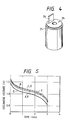
- FIG. 4 shows an internal structure of an alkaline storage battery not in accordance with the present invention.
- the alkaline storage battery of Fig. 4 is a nickel-cadmium storage battery having the nominal capacity of 1.2 Ah, and differs from the alkaline storage battery shown in FIG. 1 in that only a single upper current collector tab 24 is employed.
- the upper current collector tab 24 comprises a substantially circular current collecting tab 25 welded to the terminal edge of the positive electrode and a rectangular lead tab 26 connected to and extending upwardly from the current collecting tab 15.
- the current collecting tab 25 has a thickness of 0.15 mm, and the lead tab 26 has a thickness of 0.50 mm.
- the thicker lead tab 26 has a reduced electric resistance to the passage of a current therethrough.
- the storage battery illustrated in FIG. 4 will be referred to as a storage battery F.
- the internal resistance of the storage battery F is about 20 % lower than the internal resistance of a conventional nickel-cadmium storage battery.
- the lower current collector tab may be identical in configuration to
- Fig. 5 shows the discharge voltages of the storage batteries A, B, C, F and a conventional storage battery G, the discharge voltages being plotted against time after the storage batteries have fully recharged and then discharged with a current of 20 A flowing from the storage batteries. It can be seen from Fig. 5 that the storage batteries A, B, C, F with the reduced internal resistance exhibit higher high-rate discharge performances and higher discharge voltages than the conventional storage battery G. (Discharge curves D and E should be ignored as they do not relate to illustrated embodiments of battery).
- the alkaline storage battery has higher high-rate discharge performance, i.e. can keep a higher discharge voltage upon a high-rate discharge.
Landscapes
- Chemical & Material Sciences (AREA)
- Chemical Kinetics & Catalysis (AREA)
- Electrochemistry (AREA)
- General Chemical & Material Sciences (AREA)
- Engineering & Computer Science (AREA)
- Manufacturing & Machinery (AREA)
- Connection Of Batteries Or Terminals (AREA)
- Secondary Cells (AREA)
Description
- The present invention relates to an alkaline storage battery such as a sealed nickel-cadmium storage battery or the like, and more particularly to an alkaline storage battery having an improved current collector tab structure for increased high-rate discharge performance.
- One conventional alkaline storage battery is shown in FIGS. 6 and 7 of the accompanying drawings. The known alkaline storage battery has an
electrode assembly 34 comprising apositive electrode 32 and anegative electrode 33 which are wound as spiral coils with aseparator 31 interposed therebetween. Theelectrode assembly 34 is housed in a nickel-platedsteel case 35 which doubles as the negative terminal of the storage battery. Thepositive electrode 32 has aterminal edge 36 projecting from one end of theelectrode assembly 34, whereas thenegative electrode 33 has aterminal edge 37 projecting from the other end of theelectrode assembly 34. Theterminal edge 36 is connected to an uppercurrent collector tab 38 which comprises acircular collecting tab 39 welded to theterminal edge 36 and arectangular lead tab 40 extending from thecircular collecting tab 39, therectangular lead tab 40 having a width smaller than the diameter of thecircular collecting tab 39. Thelead tab 40 is spot-welded to a sealingcover 41 of thecase 35, thesealing cover 41 serving as the positive terminal of the storage battery. Theterminal edge 37 is connected to a lowercurrent collector tab 42 which comprises acircular collecting tab 43 welded to theterminal edge 37 and a tongue-shaped lead tab 44 attached to the center of thecircular collecting tab 43. Thelead tab 44 is spot-welded to the inner surface of the bottom of thecase 35 at the center of thecircular collecting tab 43. - It is known that the high-rate discharge performance of the alkaline storage battery of such a construction greatly varies depending on the internal resistance of the storage battery.
- The
current collector tabs terminal edges electrode assembly 34. To spot-weld such a current collector tab to a terminal edge of an electrode assembly, one surface of the current collector tab is held against the terminal edge of the electrode assembly, and a pair of spot-welding electrodes is disposed on the other surface of the current collector tab. The welding current which is supplied between the spot-welding electrodes flows from the terminal edge of the electrode assembly to the electrode assembly itself through the current collector tab. If the current collector tab, with its current collecting tab and lead tab having the same thickness, is increased in its overall thickness to reduce the electric resistance thereof, then when the current collector tab is welded to the terminal edge of the electrode assembly, the loss current flowing through the current collector tab is increased, thereby reducing the welding current flowing through the joint between the terminal edge of the electrode assembly and the current collector tab. As a result, the joint cannot be welded effectively. It is therefore preferable to reduce the thickness of the current collector tab in order to minimize the loss current which flows during the welding process. If the current collector tab is thinned, however, the electric resistance of the lead tab on which the current is concentrated is increased. Consequently, it is impossible to reduce the electric resistance of the lead tab and hence the entire current collector tab. - US-A-4322484 discloses an alkaline storage battery according to the pre-characterising part of
claim 1. - According to the present invention there is provided an alkaline storage battery comprising:
an electrode assembly including a positive electrode plate and a negative electrode plate, said plates being spirally wound with a separator interposed therebetween;
a case housing said electrode assembly therein and serving as a negative terminal, said case having an opening;
a sealing cover mounted in said opening with an insulating gasket therebetween, said sealing cover serving as a positive terminal;
negative electrode current collector means electrically connecting an edge of said negative electrode plate to said case;
positive electrode current collector means electrically connecting an edge of said positive electrode plate to said sealing cover, said positive electrode current collector means including first and second current collectors each having a current collecting part attached to said edge of the positive electrode plate and a lead part attached to said sealing cover, characterised in that said first and second current collectors define an opening therebetween in the region of the center of said electrode assembly. - Embodiments of battery in accordance with the present invention will now be described, by way of example only, with reference to the accompanying drawings in which:
- Fig. 1 is a longitudinal cross-sectional view of an alkaline storage battery according to a first embodiment of the present invention;
- Fig. 2 is a perspective view of an internal structure of the alkaline storage battery shown in Fig. 1, showing upper current collector tabs from which lead tabs extend and an electrode assembly;
- Fig. 3 is a perspective view of an internal structure of an alkaline storage battery according to a second embodiment of the present invention;
- Fig. 4 is a perspective view of an internal structure of an alkaline storage battery not in accordance with the present invention;
- Fig. 5 is a graph showing discharge performances of the alkaline storage batteries shown in Figs. 1-4 and a conventional alkaline storage battery;
- FIG. 6 is a longitudinal cross-sectional view of a conventional alkaline storage battery; and
- FIG. 7 is a perspective view of an internal structure of the conventional alkaline storage battery.
- FIGS. 1 and 2 show an alkaline storage battery according to a first embodiment of the present invention. The alkaline storage battery according to the first embodiment is in the form a nickel-cadmium storage battery having the nominal capacity of 1.2 Ah. The alkaline storage battery includes an
electrode assembly 54 comprising apositive electrode 52 and anegative electrode 53 which are wound as spiral coils with aseparator 51 interposed therebetween. Theelectrode assembly 54 is housed in a nickel-platedsteel case 55 which doubles as the negative terminal of the storage battery. Thepositive electrode 52 has aterminal edge 56 projecting from one end of theelectrode assembly 54, whereas thenegative electrode 53 has aterminal edge 57 projecting from the other end of theelectrode assembly 54. - The alkaline storage battery has two upper
current collector tabs terminal edge 56 of thepositive electrode 52. The uppercurrent collector tabs current collecting tabs terminal edge 56 of thepositive electrode 52, and respective rectangular lead tabs 7, 8 extending upwardly from thecurrent collecting tabs current collector tabs case 55, the sealing cover 10 doubling as the positive terminal of the storage battery. The sealing cover 10 is mounted in an end opening of thecase 55 with an insulating seal ring 58 therebetween. Theterminal edge 57 is connected to a lowercurrent collector tab 62 which comprises acircular collecting tab 63 spot-welded to theterminal edge 57 and a tongue-shaped lead tab 64 attached to the center of thecircular collecting tab 63. Thelead tab 64 is spot-welded to the inner surface of the bottom of thecase 55 at the center of thecircular collecting tab 63. - The storage battery thus constructed will be referred to as a storage battery A. An electric current supplied from the
current collecting tabs current collector tabs current collecting tabs current collecting tabs current collector tabs - To spot-weld the
current collecting tabs electrode assembly 54, a pair of welding electrodes is held against thecurrent collecting tabs current collecting tabs terminal edge 56 of thepositive electrode 52. - Another storage battery, referred to as a storage battery B, according to the first embodiment of the present invention is similar to the storage battery A except that upper current collector tabs have a greater thickness of 0.20 mm. The internal resistance of the storage battery B is about 25 % lower than the internal resistance of a conventional nickel-cadmium storage battery.
- While two upper current collector tabs are employed in the storage batteries of the first embodiment, more upper current collector tabs and/or a plurality of lower current collector tabs may be employed.
- FIG. 3 shows an internal structure of an alkaline storage battery according to a second embodiment of the present invention. The alkaline storage battery of the second embodiment is a nickel-cadmium storage battery having the nominal capacity of 1.2 Ah, and differs from the alkaline storage batteries of the first embodiment only with respect to two upper
current collector tabs current collector tab 11 is positioned underneath the uppercurrent collector tab 12. The uppercurrent collector tab 11 comprises a substantially circularcurrent collecting tab 13 welded to the terminal edge of the positive electrode and arectangular lead tab 15 raised, by lancing, and extending upwardly from thecurrent collecting tab 13. The other uppercurrent collector tab 12 has a substantially circularcurrent collecting tab 14 including a surface area welded to a portion of the marginal edge of the positive electrode and the other surface area welded to thecurrent collecting tab 13 and alead tab 16 raised, by lancing, and extending upwardly from thecurrent collecting tab 14. Thelead tabs - FIG. 4 shows an internal structure of an alkaline storage battery not in accordance with the present invention. The alkaline storage battery of Fig. 4 is a nickel-cadmium storage battery having the nominal capacity of 1.2 Ah, and differs from the alkaline storage battery shown in FIG. 1 in that only a single upper
current collector tab 24 is employed. The uppercurrent collector tab 24 comprises a substantially circularcurrent collecting tab 25 welded to the terminal edge of the positive electrode and arectangular lead tab 26 connected to and extending upwardly from thecurrent collecting tab 15. Thecurrent collecting tab 25 has a thickness of 0.15 mm, and thelead tab 26 has a thickness of 0.50 mm. Thethicker lead tab 26 has a reduced electric resistance to the passage of a current therethrough. The storage battery illustrated in FIG. 4 will be referred to as a storage battery F. The internal resistance of the storage battery F is about 20 % lower than the internal resistance of a conventional nickel-cadmium storage battery. The lower current collector tab may be identical in configuration to the uppercurrent collector tab 24. - The concept of using a thicker lead tab in the illustrated in Fig. 4 is applicable to the Fig. 1-3 embodiments.
- Fig. 5 shows the discharge voltages of the storage batteries A, B, C, F and a conventional storage battery G, the discharge voltages being plotted against time after the storage batteries have fully recharged and then discharged with a current of 20 A flowing from the storage batteries. It can be seen from Fig. 5 that the storage batteries A, B, C, F with the reduced internal resistance exhibit higher high-rate discharge performances and higher discharge voltages than the conventional storage battery G. (Discharge curves D and E should be ignored as they do not relate to illustrated embodiments of battery).
- With the present invention, as described above, because the electric resistance of the current collector tab or tabs is reduced, the alkaline storage battery has higher high-rate discharge performance, i.e. can keep a higher discharge voltage upon a high-rate discharge.
Claims (10)
- An alkaline storage battery comprising:
an electrode assembly (54) including a positive electrode plate (52) and a negative electrode plate (53), said plates being spirally wound with a separator (51) interposed therebetween;
a case (55) housing said electrode assembly (54) therein and serving as a negative terminal, said case having an opening;
a sealing cover (10) mounted in said opening with an insulating gasket (58) therebetween, said sealing cover serving as a positive terminal;
negative electrode current collector means (62) electrically connecting an edge (57) of said negative electrode plate (53) to said case (55);
positive electrode current collector means (1, 2) electrically connecting an edge (56) of said positive electrode plate (52) to said sealing cover (10), said positive electrode current collector means including first and second current collectors (1, 2, 11, 12) each having a current collecting part (5, 6, 13, 14) attached to said edge (56) of the positive electrode plate (52) and a lead part (7, 8, 15, 16) attached to said sealing cover (10), characterised in that said first and second current collectors (1, 2) define an opening therebetween in the region of the center of said electrode assembly (54). - An alkaline storage battery as claimed in claim 1, wherein said opening is of generally polygonal shape.
- An alkaline storage battery as claimed in claim 2, wherein said opening is of generally square shape.
- An alkaline storage battery as claimed in any of the preceding claims, wherein said opening is defined by recesses formed in the current collecting parts (5, 6, 13, 14) of the first and second current collectors (1, 2, 11, 12).
- An alkaline storage battery as claimed in claim 4, wherein the lead part (7, 8, 15, 16) of each current collector (1, 2, 11, 12) is formed by deforming it out of the plane of the current collecting part (5, 6, 13, 14) of its respective current collector to form a said recess in the current collecting part.
- An alkaline storage battery as claimed in any of the preceding claims, wherein said first and second current collectors (1, 2, 11, 12) are arranged with their lead parts (7, 8, 15, 16) in confronting relation to each other, and wherein said opening is defined between said confronting lead parts.
- An alkaline storage battery as claimed in any of the preceding claims, wherein a portion of the current collecting part (13, 14) of one of the current collectors (11, 12) is positioned over a portion of the current collecting part of the other of the current collectors.
- An alkaline storage battery as claimed in claim 7, wherein the current collecting parts of said first and second current collectors (11, 12) are welded together.
- An alkaline storage battery as claimed in any of the preceding claims, wherein more than two current collectors (1, 2, 11, 12) are provided.
- An alkaline storage battery as claimed in any of the preceding claims, wherein the lead part (7, 8, 15, 16) of at least one of said first and second current collectors (1, 2, 11, 12) is thicker than its respective current collecting part (5, 6, 13, 14).
Priority Applications (1)
| Application Number | Priority Date | Filing Date | Title |
|---|---|---|---|
| EP93102629A EP0545906B1 (en) | 1989-08-23 | 1989-10-31 | Alkaline storage battery |
Applications Claiming Priority (2)
| Application Number | Priority Date | Filing Date | Title |
|---|---|---|---|
| JP216349/89 | 1989-08-23 | ||
| JP1216349A JP2762599B2 (en) | 1989-08-23 | 1989-08-23 | Alkaline storage battery |
Related Child Applications (1)
| Application Number | Title | Priority Date | Filing Date |
|---|---|---|---|
| EP93102629.8 Division-Into | 1993-02-19 |
Publications (3)
| Publication Number | Publication Date |
|---|---|
| EP0413867A2 EP0413867A2 (en) | 1991-02-27 |
| EP0413867A3 EP0413867A3 (en) | 1991-07-31 |
| EP0413867B1 true EP0413867B1 (en) | 1994-08-17 |
Family
ID=16687160
Family Applications (2)
| Application Number | Title | Priority Date | Filing Date |
|---|---|---|---|
| EP89311254A Expired - Lifetime EP0413867B1 (en) | 1989-08-23 | 1989-10-31 | Alkaline storage battery |
| EP93102629A Expired - Lifetime EP0545906B1 (en) | 1989-08-23 | 1989-10-31 | Alkaline storage battery |
Family Applications After (1)
| Application Number | Title | Priority Date | Filing Date |
|---|---|---|---|
| EP93102629A Expired - Lifetime EP0545906B1 (en) | 1989-08-23 | 1989-10-31 | Alkaline storage battery |
Country Status (4)
| Country | Link |
|---|---|
| US (1) | US5006426A (en) |
| EP (2) | EP0413867B1 (en) |
| JP (1) | JP2762599B2 (en) |
| DE (2) | DE68917593T2 (en) |
Cited By (1)
| Publication number | Priority date | Publication date | Assignee | Title |
|---|---|---|---|---|
| US7332246B2 (en) | 2001-09-08 | 2008-02-19 | Varta Automotive Systems Gmbh | Galvanic element with a set of wound electrodes |
Families Citing this family (21)
| Publication number | Priority date | Publication date | Assignee | Title |
|---|---|---|---|---|
| JP3547927B2 (en) * | 1996-07-10 | 2004-07-28 | 三洋電機株式会社 | Alkaline storage battery and method for manufacturing the same |
| US6221524B1 (en) | 1998-01-19 | 2001-04-24 | Johnson Controls Technology Company | Strap for thin metal film battery |
| JP4538857B2 (en) * | 1998-08-07 | 2010-09-08 | 株式会社Gsユアサ | Cylindrical battery, method for manufacturing the same, and spot welding electrode for battery current collector |
| JP3695978B2 (en) | 1999-03-16 | 2005-09-14 | 三洋電機株式会社 | Alkaline storage battery with spiral electrode body |
| JP4039792B2 (en) | 1999-08-27 | 2008-01-30 | 三洋電機株式会社 | Storage battery and manufacturing method thereof |
| US6555265B1 (en) * | 2000-04-06 | 2003-04-29 | Hawker Energy Products, Inc. | Value regulated lead acid battery |
| US6509588B1 (en) * | 2000-11-03 | 2003-01-21 | Cardiac Pacemakers, Inc. | Method for interconnecting anodes and cathodes in a flat capacitor |
| FR2824667B1 (en) | 2001-05-14 | 2004-07-02 | Cit Alcatel | INTERNAL CONNECTION FOR HIGH POWER ELECTROCHEMICAL GENERATOR |
| JP3877619B2 (en) * | 2002-03-15 | 2007-02-07 | 三洋電機株式会社 | Sealed battery |
| US7479349B2 (en) | 2002-12-31 | 2009-01-20 | Cardiac Pacemakers, Inc. | Batteries including a flat plate design |
| KR100536253B1 (en) * | 2004-03-24 | 2005-12-12 | 삼성에스디아이 주식회사 | Secondary battery |
| US20070128472A1 (en) * | 2005-10-27 | 2007-06-07 | Tierney T K | Cell Assembly and Casing Assembly for a Power Storage Device |
| US8202653B2 (en) * | 2006-10-23 | 2012-06-19 | Axion Power International, Inc. | Electrode with reduced resistance grid and hybrid energy storage device having same |
| US20080113268A1 (en) * | 2006-10-23 | 2008-05-15 | Buiel Edward R | Recombinant Hybrid Energy Storage Device |
| KR101050012B1 (en) * | 2006-10-23 | 2011-07-19 | 액시온 파워 인터네셔널, 인크. | Hybrid energy storage device and manufacturing method thereof |
| US20090035657A1 (en) * | 2006-10-23 | 2009-02-05 | Buiel Edward R | Electrode for Hybrid Energy Storage Device and Method of Making Same |
| US7881042B2 (en) * | 2006-10-26 | 2011-02-01 | Axion Power International, Inc. | Cell assembly for an energy storage device with activated carbon electrodes |
| KR100879297B1 (en) * | 2007-09-27 | 2009-01-19 | 삼성에스디아이 주식회사 | Secondary battery |
| US20090103242A1 (en) * | 2007-10-19 | 2009-04-23 | Axion Power International, Inc. | Electrode with Reduced Resistance Grid and Hybrid Energy Storage Device Having Same |
| US9525161B2 (en) * | 2013-07-18 | 2016-12-20 | Samsung Sdi Co., Ltd. | Rechargeable battery |
| CN111146508A (en) * | 2020-01-11 | 2020-05-12 | 湖南科霸汽车动力电池有限责任公司 | Preparation method of sealed cylindrical nickel-hydrogen single battery and battery pack for rail transit |
Family Cites Families (16)
| Publication number | Priority date | Publication date | Assignee | Title |
|---|---|---|---|---|
| US3503806A (en) * | 1967-09-01 | 1970-03-31 | Gen Electric | Rechargeable battery of the spiral wound plate type |
| FR2039536A5 (en) * | 1969-04-02 | 1971-01-15 | Accumulateurs Fixes | |
| FR2097301A5 (en) * | 1970-07-01 | 1972-03-03 | Accumulateurs Fixes | |
| US3695935A (en) * | 1970-10-07 | 1972-10-03 | Gen Electric | Battery coil construction having a ruffled edge electrode |
| GB1422782A (en) * | 1972-04-06 | 1976-01-28 | Alkaline Batteries Ltd | Alkaline electric cells |
| US3900340A (en) * | 1973-11-13 | 1975-08-19 | Union Carbide Corp | Galvanic cell structures employing coiled electrodes |
| US3960603A (en) * | 1974-04-15 | 1976-06-01 | Sanyo Electric Co., Ltd. | Alkaline battery |
| US4049882A (en) * | 1976-02-11 | 1977-09-20 | Union Carbide Corporation | Battery assembly |
| US4322484A (en) * | 1978-09-05 | 1982-03-30 | General Electric Company | Spiral wound electrochemical cell having high capacity |
| US4255500A (en) * | 1979-03-29 | 1981-03-10 | General Electric Company | Vibration resistant electrochemical cell having deformed casing and method of making same |
| JPS606073B2 (en) * | 1979-11-07 | 1985-02-15 | 松下電器産業株式会社 | Method for manufacturing a battery with a spiral electrode body |
| DE3019186A1 (en) * | 1980-05-20 | 1981-11-26 | Varta Batterie Ag, 3000 Hannover | Gas-tightly closed accumulator with wound electrodes - has pole tap plate with dependent tongue, bent back against plate at sharp angle and connected to cell lid |
| US4452869A (en) * | 1981-11-02 | 1984-06-05 | General Electric Company | Battery with improved terminal structure |
| US4554227A (en) * | 1983-07-18 | 1985-11-19 | Japan Storage Battery Company Limited | Alkaline battery |
| JPS61281457A (en) * | 1985-09-13 | 1986-12-11 | Sanyo Electric Co Ltd | Manufacture of storage battery |
| US4664989A (en) * | 1985-10-03 | 1987-05-12 | Union Carbide Corporation | Liquid cathode cell system employing a coiled electrode assembly |
-
1989
- 1989-08-23 JP JP1216349A patent/JP2762599B2/en not_active Expired - Lifetime
- 1989-10-26 US US07/426,640 patent/US5006426A/en not_active Expired - Lifetime
- 1989-10-31 DE DE68917593T patent/DE68917593T2/en not_active Expired - Fee Related
- 1989-10-31 EP EP89311254A patent/EP0413867B1/en not_active Expired - Lifetime
- 1989-10-31 DE DE68925431T patent/DE68925431T2/en not_active Expired - Fee Related
- 1989-10-31 EP EP93102629A patent/EP0545906B1/en not_active Expired - Lifetime
Cited By (1)
| Publication number | Priority date | Publication date | Assignee | Title |
|---|---|---|---|---|
| US7332246B2 (en) | 2001-09-08 | 2008-02-19 | Varta Automotive Systems Gmbh | Galvanic element with a set of wound electrodes |
Also Published As
| Publication number | Publication date |
|---|---|
| JP2762599B2 (en) | 1998-06-04 |
| US5006426A (en) | 1991-04-09 |
| JPH0378964A (en) | 1991-04-04 |
| EP0545906A2 (en) | 1993-06-09 |
| EP0545906A3 (en) | 1994-07-13 |
| DE68917593T2 (en) | 1995-01-05 |
| DE68925431D1 (en) | 1996-02-22 |
| EP0413867A2 (en) | 1991-02-27 |
| DE68925431T2 (en) | 1996-05-30 |
| DE68917593D1 (en) | 1994-09-22 |
| EP0413867A3 (en) | 1991-07-31 |
| EP0545906B1 (en) | 1996-01-10 |
Similar Documents
| Publication | Publication Date | Title |
|---|---|---|
| EP0413867B1 (en) | Alkaline storage battery | |
| EP0494504B1 (en) | Alkaline storage battery | |
| EP0921581B1 (en) | Current collector for spirally wound cylindrical storage batteries | |
| EP1279198B1 (en) | High performance battery and current collector therefor | |
| US6010801A (en) | Cylindrical storage battery | |
| US8173288B2 (en) | Secondary battery | |
| AU2001261222A1 (en) | High performance battery and current collector therefor | |
| JP2005100949A (en) | Cylindrical battery and manufacturing method thereof | |
| JP3951526B2 (en) | Cylindrical storage battery | |
| EP0453292B1 (en) | Lead acid storage battery | |
| JPH0636756A (en) | Cylindrical battery | |
| JP2982350B2 (en) | Lead storage battery | |
| JPH0418432B2 (en) | ||
| JPS6134695Y2 (en) | ||
| JPH0312212Y2 (en) | ||
| JP3649876B2 (en) | Cylindrical secondary battery | |
| JP3416269B2 (en) | Prismatic sealed battery | |
| JPH067564Y2 (en) | Sealed nickel-cadmium storage battery | |
| JPH09298055A (en) | Cylindrical secondary battery | |
| JP2538719Y2 (en) | Cylindrical storage battery | |
| JPH1167187A (en) | Battery and manufacturing method thereof | |
| JP2000156217A (en) | Cylindrical storage battery and its manufacturing method | |
| JPH01115057A (en) | Alkaline storage battery |
Legal Events
| Date | Code | Title | Description |
|---|---|---|---|
| PUAI | Public reference made under article 153(3) epc to a published international application that has entered the european phase |
Free format text: ORIGINAL CODE: 0009012 |
|
| 17P | Request for examination filed |
Effective date: 19891110 |
|
| AK | Designated contracting states |
Kind code of ref document: A2 Designated state(s): DE FR GB NL |
|
| PUAL | Search report despatched |
Free format text: ORIGINAL CODE: 0009013 |
|
| AK | Designated contracting states |
Kind code of ref document: A3 Designated state(s): DE FR GB NL |
|
| 17Q | First examination report despatched |
Effective date: 19920814 |
|
| GRAA | (expected) grant |
Free format text: ORIGINAL CODE: 0009210 |
|
| AK | Designated contracting states |
Kind code of ref document: B1 Designated state(s): DE FR GB NL |
|
| ET | Fr: translation filed | ||
| REF | Corresponds to: |
Ref document number: 68917593 Country of ref document: DE Date of ref document: 19940922 |
|
| PLBE | No opposition filed within time limit |
Free format text: ORIGINAL CODE: 0009261 |
|
| STAA | Information on the status of an ep patent application or granted ep patent |
Free format text: STATUS: NO OPPOSITION FILED WITHIN TIME LIMIT |
|
| 26N | No opposition filed | ||
| REG | Reference to a national code |
Ref country code: GB Ref legal event code: 746 Effective date: 19970901 |
|
| PGFP | Annual fee paid to national office [announced via postgrant information from national office to epo] |
Ref country code: FR Payment date: 19991011 Year of fee payment: 11 |
|
| PGFP | Annual fee paid to national office [announced via postgrant information from national office to epo] |
Ref country code: GB Payment date: 19991027 Year of fee payment: 11 |
|
| PGFP | Annual fee paid to national office [announced via postgrant information from national office to epo] |
Ref country code: DE Payment date: 19991102 Year of fee payment: 11 |
|
| PG25 | Lapsed in a contracting state [announced via postgrant information from national office to epo] |
Ref country code: GB Free format text: LAPSE BECAUSE OF NON-PAYMENT OF DUE FEES Effective date: 20001031 |
|
| GBPC | Gb: european patent ceased through non-payment of renewal fee |
Effective date: 20001031 |
|
| PG25 | Lapsed in a contracting state [announced via postgrant information from national office to epo] |
Ref country code: FR Free format text: LAPSE BECAUSE OF NON-PAYMENT OF DUE FEES Effective date: 20010629 |
|
| PG25 | Lapsed in a contracting state [announced via postgrant information from national office to epo] |
Ref country code: DE Free format text: LAPSE BECAUSE OF NON-PAYMENT OF DUE FEES Effective date: 20010703 |
|
| REG | Reference to a national code |
Ref country code: FR Ref legal event code: ST |
|
| PGFP | Annual fee paid to national office [announced via postgrant information from national office to epo] |
Ref country code: NL Payment date: 20081015 Year of fee payment: 20 |
|
| NLV7 | Nl: ceased due to reaching the maximum lifetime of a patent |
Effective date: 20091031 |
|
| PG25 | Lapsed in a contracting state [announced via postgrant information from national office to epo] |
Ref country code: NL Free format text: LAPSE BECAUSE OF EXPIRATION OF PROTECTION Effective date: 20091031 |