EP0413586A2 - System zum Durchgang von Hilfsmittelinformation - Google Patents
System zum Durchgang von Hilfsmittelinformation Download PDFInfo
- Publication number
- EP0413586A2 EP0413586A2 EP90309008A EP90309008A EP0413586A2 EP 0413586 A2 EP0413586 A2 EP 0413586A2 EP 90309008 A EP90309008 A EP 90309008A EP 90309008 A EP90309008 A EP 90309008A EP 0413586 A2 EP0413586 A2 EP 0413586A2
- Authority
- EP
- European Patent Office
- Prior art keywords
- information
- pass
- actual process
- resource information
- area
- Prior art date
- Legal status (The legal status is an assumption and is not a legal conclusion. Google has not performed a legal analysis and makes no representation as to the accuracy of the status listed.)
- Granted
Links
Images


Classifications
-
- G—PHYSICS
- G06—COMPUTING; CALCULATING OR COUNTING
- G06F—ELECTRIC DIGITAL DATA PROCESSING
- G06F11/00—Error detection; Error correction; Monitoring
- G06F11/07—Responding to the occurrence of a fault, e.g. fault tolerance
- G06F11/14—Error detection or correction of the data by redundancy in operation
- G06F11/1479—Generic software techniques for error detection or fault masking
- G06F11/1482—Generic software techniques for error detection or fault masking by means of middleware or OS functionality
-
- G—PHYSICS
- G06—COMPUTING; CALCULATING OR COUNTING
- G06F—ELECTRIC DIGITAL DATA PROCESSING
- G06F11/00—Error detection; Error correction; Monitoring
- G06F11/07—Responding to the occurrence of a fault, e.g. fault tolerance
- G06F11/14—Error detection or correction of the data by redundancy in operation
- G06F11/1479—Generic software techniques for error detection or fault masking
- G06F11/1492—Generic software techniques for error detection or fault masking by run-time replication performed by the application software
-
- G—PHYSICS
- G06—COMPUTING; CALCULATING OR COUNTING
- G06F—ELECTRIC DIGITAL DATA PROCESSING
- G06F11/00—Error detection; Error correction; Monitoring
- G06F11/07—Responding to the occurrence of a fault, e.g. fault tolerance
- G06F11/16—Error detection or correction of the data by redundancy in hardware
- G06F11/20—Error detection or correction of the data by redundancy in hardware using active fault-masking, e.g. by switching out faulty elements or by switching in spare elements
- G06F11/2097—Error detection or correction of the data by redundancy in hardware using active fault-masking, e.g. by switching out faulty elements or by switching in spare elements maintaining the standby controller/processing unit updated
Definitions
- This invention relates to a data assurance processing system for handling passed-through information. It makes fault tolerant a computer system whose back-up process takes tasks over continually from an actual process at failure by passing through information stored in a shared memory (such as a non-volatile shared memory) from the actual process to the back-up process.
- a shared memory such as a non-volatile shared memory
- An effective way of making a computer system fault tolerant is to have two controlling processes: one for a normal operation, and the other as a back-up for continuing a controlling operation in the event of a failure of the controlling process for the normal operation.
- the former controlling process is called an actual process and the latter is called a back-up process.
- the resource information can be effectively passed from the actual process to the back-up process through a non-volatile shared memory such as a semiconductor external memory device, commonly accessible by the two processes.
- Two methods can be considered for passing resource information through a non-volatile shared memory.
- One is to pass the resource information in a batch at a crash time of the actual process.
- the other is to pass the resource information sequentially when the actual process is operating.
- the back-up process 32 must take over a dynamically changing operating environment handled by the actual process 31, when the actual process 31 is caused to fail by faults.
- the performance of switching from the actual process 31 to the back-up process 32 deteriorates, because it takes time to set the operating environment based on the passed-through information.
- the first method in which the resource information is passed through in a batch at the crash time of the actual process, has a problem of switching performance deterioration. This is because it takes time to transmit and set all resource information at the crash time.
- the second prior art method cannot yet meet the above two conditions simultaneously, since an area of non-volatile shared memory 30 is used only as a single structure. For instance, data integrity cannot always be guaranteed when the back-up process 32 simultaneously reads the portion being written by the actual process 31. If an exclusive control such as a lock control is made to counter this, the processing of the actual process 31 can be kept waiting, and a problem of slow response may arise in an ordinary operation.
- An object of the present invention is to solve the above problems and to make the advance building of the operating environment for fault tolerance efficient and sure.
- a feature of the present invention resides in a system to pass-through resource information characterized by switching g two sets of areas each having the actual process and the back-up process, with the two sets described as follows.
- a computer system with an actual process and a back-up process that passes through resource information necessary to continue handling tasks stored in a shared memory from the actual process to the back-up process at least at a crash time of the actual process two sets of areas composed of an original information area that stores information that must be transmitted from the actual process to the back-up process and a difference area that memorizes the information related to the change when the actual process changes the original information area are set in the shared memory
- the back-up process reads out the pass-through information stored in the difference area of the one one of the two sets and passes through the information related to the change
- the actual process sores the changed information that must be transmitted to the back-up process to the original information area of the back-up process and the information related to the change to the difference area of the back-up process and copies the original information memorized
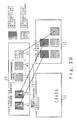
- FIGS. 2A and 2B are drawings which explain the first principle of this invention.
- 10 is a non-volatile shared memory
- 11 is an actual process for an ordinary operation
- 12 is a back-up process waiting to continue tasks at the failure time of the actual process
- 13 is a processing of the intermittent pass-through
- 14 is a processing of the batch pass-through.
- A1, A2, B1-B3 represent the resource information to be passed through.
- resource information passed through from the actual process 11 to the back-up process 12 is preclassified into two groups in accordance with a frequency of change.
- the first group consists of constantly changing pass-through information such as about a condition change like pass-through information during a data transmission or during establishing of a connection, etc.
- the second group consists of pass-through information, such as about completion of a connection, which changes only once in a while in stead of continually. i.e., the first group has resource information with relatively high change frequencies, and said second group has that with relatively low change frequencies.
- Resource information herein refers to the information which is required for being passed through to make the system fault-tolerant.
- the actual process 11 writes the changed resource information in the non-volatile shared memory 10 when the pieces of resource information are changed during an ordinary operation.
- the pieces of pass-through information A1 and A2 in the first group are stored in the non-volatile shared memory 10, as they are.
- the pieces of pass-through information B1-B3 in the second group are intermittently passed through to the back-up process 12 at a set time interval or when the amount of change information reaches a preset predetermined value.
- the back-up process 12 takes in the bits of information into itself, because the amounts of pass-through information B1 and B2 reach the predetermined value.
- the back-up process 12 takes over the bits of pass-through information A1, A2 and B3 not yet completely carried over during an ordinary operation, when it is notified of the crash of the actual process 11.
- Bits of pass-through information A1 and A2 in the first group are carried over in a batch.
- bits of pass-through information in the second group only the remaining ones not passed through in the intermittent pass-through processing 13 are carried over.
- the bits of pass-through information, A1 and A2, in the first group with high change frequencies are carried over from the actual process 11 to the back-up process 12 in the batch pass-through processing 14 at a crash time of the actual process 11, as shown in Figure 2B.
- the overhead for the pass-through during an ordinary operation of the actual process 11 can be reduced.
- the bits of pass-through information, B1-B3, in the second group with low change frequencies are carried over from the actual process 11 to the back-up process 12 in the intermittent pass-through processing 13 during an ordinary operation, as shown in Figure 2A.
- the back-up process 12 takes over, at a crash time of the actual process 11, only the bits of pass-through information A1 and A2 in the first group and B3 in the second group not carried over during an intermittent pass-through. Consequently, when the actual process 11 is crashed, bits of information already passed through by the intermittent processing 13 need not be carried over, and the processing time required for the information carrying-over can be reduced, thereby improving the switching performance.
- the joint use of the batch pass-through processing 14 and the intermittent pass-through processing 13 enables an efficient reduction in overhead both during an ordinary operation and at a crash time.
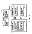
- Figure 3 shows an example of a system to which this invention is applied.
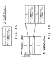
- Figure 4 shows an example of a data structure of the pass-through information related to the embodiment of this invention.
- Figure 5 shows the processing flow of an actual process during an ordinary operation related to the embodiment of this invention.
- Figure 6 shows the processing flow of a back-up process during an ordinary operation related to the embodiment of this invention.
- Figure 7 shows the processing flow of a back-up process at a crash time related to the embodiment of this invention.
- FIG. 3 the same alphanumerics as in Figure 2 correspond to the same components.
- 20 is a non-volatile shared memory for a batch pass-through.
- 21 is a non-volatile shared memory for an intermittent pass-through.
- 22-1 and 22-2 are processor modules (PM) each equipped with a CPU, a memory and so forth.
- 23 is a processing part for writing pass-through information.
- 24 is a judging part for an intermittent pass-through.
- 25 is a directing part for an intermittent pass-through.
- 26 is a processing part for a batch pass-through at a crash time.
- 27 is a processing part for an intermittent pass-through. 28 are buses.
- Processor modules 22-1 and 22-2 are physical units that can exclusively use a CPU and a memory.
- Buses 28 are data transmission passes that interconnect among processor modules and that connect the non-volatile shared memory 10 and the processor module.
- non-volatile shared memory 10 Established within the non-volatile shared memory 10 are an area of the non-volatile shared memory for a batch pass-through 20 storing batch pass-through information and an area of the non-volatile shared memory for an intermittent pass-through 21 storing intermittent pass-through information.
- the processor modules 22-1 and 22-2 each have a control monitor for process execution within a respective processor module unit, and under this monitor's control the actual process 11 is operating within the processor module 22-1 and the back-up process 12 is set in the processor module 22-2 and stands-by.
- the processing part for writing pass-through information 23 in the actual process 11 judges the sort of resource information, and writes the one in the first group to the non-volatile shared memory for a batch pass-through 20, and writes the one in the second group to the non-volatile shared memory for an intermittent pass-through 21.
- the judging part for an intermittent pass-through 24 determines whether an intermittent pass-through processing is currently necessary or not, and it directs the back-up process 12 to receive intermittent pass-through via a directing part for intermittent pass-through 25 when the change amount exceeds the predetermined value and a pass-through is necessary.
- the back-up process 12 begins processing of the pass-through resource information either by a crash notification of the actual process 11 from a fault detection part not shown in the drawing or by a directive from the directing part for the intermittent pass-through. It processes pass-through resource information via the processing part for a batch pass-through 26 at the crash notification, as shown in Figure 2B. It processes pass-through resource information via the processing part for an intermittent pass-through 27 at the directive for an intermittent pass-through by referring to the non-volatile shared memory for an intermittent pass-through 21, as shown in Figure 2A.
- the data structure of the batch pass-through information stored in the non-volatile shared memory for a batch pass-through 20 is shown in Figure 4A.
- *1 is a usage or in-use flag for showing whether the information is valid or not.
- *2 is a storage area for information classification.
- the intermittent pass-through information stored in the non-volatile shared memory for an intermittent pass-through 21 is controlled using an entry for an intermittent pass-through, as shown in Figure 4B.
- *1 is a usage flag for showing whether the information is valid or not.
- *2 is a storage area for information classification. Each entry registers one pass-through worth of information.
- the information classification refers to pass-through information during a data transmission, or during establishing of a connection, or upon completion of a connection. As described before, the pass-through information during a data transmission, while establishing a connection, etc. is information for a batch pass-through, whereas the pass-through information about completion of a connection is information for an intermittent pass-through.
- S1 judges whether or not a demand to write resource information in the non-volatile shared memory 20 is actually one to write it in the non-volatile shared memory for a batch pass-through shown in Figure 3. In other words, S1 judges whether the resource information belongs to the first group (for batch processing) or the second group (for intermittent processing). An intermittent pass-through case goes on to a processing S4.
- S2 acquires a storage area for pass-through information in the non-volatile shared memory for a batch pass-through 20 in a batch pass-through case.
- S3 turns ON the usage flag in the storage area for pass-through information, sets the information classification, and writes the pass-through information demanded to be written in the storage area for pass-through information. It then finishes its own processing.
- S4 acquires a storage area for pass-through information from the non-volatile shared memory for an intermittent pass-through 21 in an intermittent pass-through case.
- S5 writes pass-through information in the storage area for pass-through information.
- S6 makes an entry for an intermittent pass-through in use and makes an entry in a storage area for pass-through information. Then, S6 turns ON the usage flag designating that the storage area for pass-through information is used.
- S8 invokes time monitoring with a timer, if they do not reach the predetermined value.
- the intermittent pass - through in the embodiment of this invention is made, when there is no intermittent pass-through after a certain time period has elapsed since the last intermittent pass-through information is written. Therefor, S8 invokes time monitoring with the timer after the last intermittent pass-through information is written. S8 stops its own processing after this invoking of the time monitoring. Meanwhile, after said invoking of the time monitoring, when a TIME OUT signal is received, processing S9 is executed.
- S9 directs the back-up process 12 to intermittently take over resource information and stops its own processing.
- the back-up process 12 executes processings S10 and S11 shown in Figure 6.
- S10 reads the pass-through information from the storage area for pass-through information entered in an entry for an intermittent pass-through shown in Figure 4B.
- S11 judges pass-through information by information classification in a storage area for pass-through information, reflects it to the back-up process 12 and turns OFF the usage flag. S11 then stands by for the next instruction.
- the back-up process 12 executes processings S15-S20 shown in Figure 7 by activating the processing part for a batch pass-through at a crash time 26, when it receives a crash notification of the actual process 11.
- S15 reads an intermittent pass-through entry from the non-volatile shared memory for an intermittent pass-through 21 and checks whether or not there is an entry of registered pass-through information.
- S16 advances to a processing S17 if the usage flag is ON and skips it if the usage flag is OFF. The usage flag ON indicates the existence of an entry.
- S17 reads information from the storage area for pass-through information entered in the entry for an intermittent pass-through and reflects it in the back-up process 12.
- S18 reads the content of the storage area for pass-through information from the non-volatile shared memory for a batch pass-through 20.
- S19 judges whether the usage flag of the storage area for the pass-through information is ON or not.
- S19 advances to the next processing S20, if the usage flag is ON.
- S20 reflects batch pass-through information to the back-up process 12. If all the above pass-through processings are completed, the back-up process 12 resumes its tasks as the actual process.
- Figure 8 is a drawing for explaining the second principle of this invention.
- 31 is an actual process taking place during an ordinary operation
- 32 is a back-up process for continuing to handle tasks at a fault time of the actual process
- 30 is a non-volatile shared memory
- 33A and 33B are storage areas for pass-through information respectively called a current version and a new version
- 34A and 34B are difference areas
- 35A and 35B are original information areas
- 36 is a non-volatile shared memory control process.
- the non-volatile shared memory 30 is a memory device whose memory contents are assured, even if the execution of the actual process 31 or the back-up process 32 halts. It may consist, for example, of components like semiconductor memory devices with a power source of a different system.
- Pass-through resource information such as that about the operating environment of the actual process 31, is set sequentially in the non-volatile shared memory 30, and the back-up process 32 builds its operating environment beforehand, so that the back-up process 32 can be substituted for the actual process 31 at 31's fault time to handle 31's tasks.
- the area of the non-volatile shared memory 30 in which this pass-through information is set has a dual structure with the current version 33A and the new version 33B.
- Both the current version 33A and the new version 33B have original information areas 35A and 35B, respectively, for storing the information to be transmitted from the actual process 31 to the back-up process 32 and difference areas 34A and 34B, respectively, for storing the changed information.
- the actual process 31 revises the contents of the original information area 35A of the current version 33A and sets the information (about which information in its original information area 35A was changed) in the difference area 34A, when pass-through information such as that about the operating environment is generated.
- a processing P2 copies the contents of the original information area 35A to the original information area 35B, when a certain time period has elapsed or the volume of change reaches a predetermined value. At this time, the difference area 16A is not copied. Next, it asks non-volatile shared memory controlling process 36 for a processing to switch the current version 33A to a new version and the new version 33B to a current version.
- a processing P3 makes an intermittent synchronous notification, whose meaning is asking to reflect the pass-through information, to the back-up process 32.
- the back-up process 32 reads out contents from the new version 33B and reflects them in the back-up process 32 to prebuild its own operating environment, while the actual process 31 performs writing into the current version 33A.
- a time interval and an amount of information change which are factors in invoking an intermittent synchronous processing, are determined.
- the back-up process 32 completes its own advance building of the operating environment from the new version 33B, while the actual process 31 performs writing into the current version 33A.
- the back-up process 32 when the actual process 31 makes an intermittent synchronous notification, since new pass-through information is notified, the back-up process 32, by judging that the former current version 33A is the current new version after inquiring to the non-volatile shared memory control process 36, makes the area of the current new version as new read-out object of the pass-through information.
- the actual process 31 adds a sequence number (increment of one for every notification) in an intermittent synchronous notification, so that the the back-up process 32 can judge, in particular, whether intermittent synchronous processings are being made in the right cycle.
- the original information area copies the information in the original information area 35A to the original information area 35B of the next current version 33B at a switching time between the current version and the new version, so that all the pass-through information is always kept.
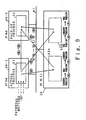
- Figure 9 shows a second preferred embodiment of this invention.
- FIG. 9 the same alphanumerics as in Figure 8 correspond to each other, 40-1 and 40-2, respectively, are processor modules (PM: physical units that can exclusively use a CPU or a memory) and 41 are buses (SS-BUS:transmission paths that either interconnect among PMs or connect between a PM and a non-volatile shared memory 30).
- processor modules PM: physical units that can exclusively use a CPU or a memory
- SS-BUS transmission paths that either interconnect among PMs or connect between a PM and a non-volatile shared memory 30.
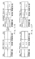
- Figure 10 shows the data structure in a non-volatile shared memory area related to the second embodiment of this invention.
- the data structure of the non-volatile shared memory area is made to consist of a dual structure with the current version 33A and the new version 33B as shown in Figure 9 to enable intermittent transmission of the pass-through information from an actual process to a back-up process.
- This information pass-through is triggered by elapsing of a certain time period or accumulation of information volume over a certain predetermined value, but it relates only to the changed information instead of all information in the area of the non-volatile shared memory 30.
- the difference areas 34A and 34B enable the identification of the changed information at a back-up process and they store pointers to the original information areas 35A and 35B, where the actual pass-through information, i.e. all the information to be transmitted from the actual process to the back-up process, is stored. However, since a part of such information that becomes unnecessary depending on the tasks of the actual process is abandoned during this procedure, the original information areas 35A and 35B will not overflow.
- the communication control process needs to transmit the information as to which characteristic of the communication resource was activated, when communication resource, such as a data transmission line or a data link, is activated. Also, when the communication resource is deactivated, the communication control process needs to transmit the information as to which resource already transmitted was deactivated. After the notification of this deactivation, the pass-through information such as resource characteristics becomes no longer necessary, and needs not be maintained in the original information areas 35A and 35B.
- the current version 33A is an area for the actual process for writing the pass-through information.
- the new version 33B is an area for the back-up process for reading out the pass-through information. Accordingly, the pointer format of the current version from the difference area 34A to the original information area 35A and the pointer format of the new version from the difference area 34B to the original information area 35B are different.
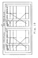
- Figures 11A through 11F are a processing example related to the second embodiment of this invention.
- a process flow of the actual process and the back-up process is shown in detail in Figures 11A through 11F, where the activating and deactivating of a data transmission line, which is a communication resource, are taken as the example.
- the entry numbers for the difference areas 34A and 34B are assumed to be 2 and the information volume in the original information areas 35A and 35B is assumed to be 4.
- Deactivation herein refers to abandoning of the resource information as a result.
- this invention has benefits in that the processings by the actual process can avoid being kept on hold by intermittent prebuilding of the operating environment in the back-up process and that the loss of pass-through information due to a delay in the processing by the back-up process can be prevented. Thus, it makes such thing as a communication control program fault tolerant with certainty.
- this invention enables not only the performance maintenance during an ordinary operation of the actual process but also the switching performance improvement at a crash time of the actual process.
Landscapes
- Engineering & Computer Science (AREA)
- Theoretical Computer Science (AREA)
- Quality & Reliability (AREA)
- Physics & Mathematics (AREA)
- General Engineering & Computer Science (AREA)
- General Physics & Mathematics (AREA)
- Hardware Redundancy (AREA)
- Information Retrieval, Db Structures And Fs Structures Therefor (AREA)
Applications Claiming Priority (4)
| Application Number | Priority Date | Filing Date | Title |
|---|---|---|---|
| JP1211991A JP2772052B2 (ja) | 1989-08-17 | 1989-08-17 | 資源情報引き継ぎ処理方法 |
| JP211991/89 | 1989-08-17 | ||
| JP266425/89 | 1989-10-13 | ||
| JP1266425A JP2772068B2 (ja) | 1989-10-13 | 1989-10-13 | 引き継ぎ情報のデータ保証処理方法 |
Publications (3)
| Publication Number | Publication Date |
|---|---|
| EP0413586A2 true EP0413586A2 (de) | 1991-02-20 |
| EP0413586A3 EP0413586A3 (en) | 1992-05-27 |
| EP0413586B1 EP0413586B1 (de) | 1998-01-21 |
Family
ID=26518950
Family Applications (1)
| Application Number | Title | Priority Date | Filing Date |
|---|---|---|---|
| EP90309008A Expired - Lifetime EP0413586B1 (de) | 1989-08-17 | 1990-08-16 | System zum Durchgang von Hilfsmittelinformation |
Country Status (4)
| Country | Link |
|---|---|
| US (1) | US5446875A (de) |
| EP (1) | EP0413586B1 (de) |
| AU (1) | AU645757B2 (de) |
| DE (1) | DE69031965T2 (de) |
Families Citing this family (7)
| Publication number | Priority date | Publication date | Assignee | Title |
|---|---|---|---|---|
| US6704923B1 (en) | 1994-12-20 | 2004-03-09 | Sun Microsystems, Inc. | System and method for pre-verification of stack usage in bytecode program loops |
| US5748964A (en) * | 1994-12-20 | 1998-05-05 | Sun Microsystems, Inc. | Bytecode program interpreter apparatus and method with pre-verification of data type restrictions |
| US5668999A (en) * | 1994-12-20 | 1997-09-16 | Sun Microsystems, Inc. | System and method for pre-verification of stack usage in bytecode program loops |
| SE516542C2 (sv) * | 1999-07-01 | 2002-01-29 | Ericsson Telefon Ab L M | Metod och anordning för övervakning av parallella processer |
| US7120572B1 (en) | 2000-01-06 | 2006-10-10 | Sun Microsystems, Inc. | Memory efficient program pre-execution verifier and method |
| WO2001065371A2 (en) * | 2000-03-01 | 2001-09-07 | Computer Associates Think, Inc. | Method and system for updating an archive of a computer file |
| US8495019B2 (en) | 2011-03-08 | 2013-07-23 | Ca, Inc. | System and method for providing assured recovery and replication |
Citations (1)
| Publication number | Priority date | Publication date | Assignee | Title |
|---|---|---|---|---|
| EP0156179A2 (de) * | 1984-03-27 | 1985-10-02 | International Business Machines Corporation | Schutzverfahren für einen flüchtigen Primärspeicher in einem gestuften Speichersystem |
Family Cites Families (3)
| Publication number | Priority date | Publication date | Assignee | Title |
|---|---|---|---|---|
| EP0228559A1 (de) * | 1985-12-17 | 1987-07-15 | BBC Brown Boveri AG | Fehlertolerante Mehrrechneranordnung |
| US4751702A (en) * | 1986-02-10 | 1988-06-14 | International Business Machines Corporation | Improving availability of a restartable staged storage data base system that uses logging facilities |
| US4823261A (en) * | 1986-11-24 | 1989-04-18 | International Business Machines Corp. | Multiprocessor system for updating status information through flip-flopping read version and write version of checkpoint data |
-
1990
- 1990-08-16 EP EP90309008A patent/EP0413586B1/de not_active Expired - Lifetime
- 1990-08-16 AU AU61081/90A patent/AU645757B2/en not_active Ceased
- 1990-08-16 DE DE69031965T patent/DE69031965T2/de not_active Expired - Fee Related
-
1994
- 1994-01-14 US US08/181,368 patent/US5446875A/en not_active Expired - Lifetime
Patent Citations (1)
| Publication number | Priority date | Publication date | Assignee | Title |
|---|---|---|---|---|
| EP0156179A2 (de) * | 1984-03-27 | 1985-10-02 | International Business Machines Corporation | Schutzverfahren für einen flüchtigen Primärspeicher in einem gestuften Speichersystem |
Non-Patent Citations (2)
| Title |
|---|
| IBM TECHNICAL DISCLOSURE BULLETIN. vol. 20, no. 5, October 1977, NEW YORK US pages 1955 - 1958; N. K. OUCHI ET AL.: 'CHECK POINT COPY FOR A TWO-STAGE STORE' * |
| IBM TECHNICAL DISCLOSURE BULLETIN. vol. 30, no. 6, November 1987, NEW YORK US pages 351 - 353; 'ROLLING CHECKPOINT IN A TRANSACTION PROCESSING SYSTEM' * |
Also Published As
| Publication number | Publication date |
|---|---|
| EP0413586A3 (en) | 1992-05-27 |
| DE69031965T2 (de) | 1998-04-30 |
| AU6108190A (en) | 1991-02-21 |
| AU645757B2 (en) | 1994-01-27 |
| EP0413586B1 (de) | 1998-01-21 |
| DE69031965D1 (de) | 1998-02-26 |
| US5446875A (en) | 1995-08-29 |
Similar Documents
| Publication | Publication Date | Title |
|---|---|---|
| US5933347A (en) | Industrial controller with program synchronized updating of back-up controller | |
| US6411857B1 (en) | Redundant, multitasking industrial controllers with synchronized data tables | |
| US4628508A (en) | Computer of processor control systems | |
| US5235700A (en) | Checkpointing mechanism for fault-tolerant systems | |
| CA2091993C (en) | Fault tolerant computer system | |
| US5777874A (en) | Programmable controller backup system | |
| US5491787A (en) | Fault tolerant digital computer system having two processors which periodically alternate as master and slave | |
| US5440726A (en) | Progressive retry method and apparatus having reusable software modules for software failure recovery in multi-process message-passing applications | |
| CA1223078A (en) | Queuing arrangement | |
| US5590277A (en) | Progressive retry method and apparatus for software failure recovery in multi-process message-passing applications | |
| US4941087A (en) | System for bumpless changeover between active units and backup units by establishing rollback points and logging write and read operations | |
| JPH0371201A (ja) | フェイルセーフ・データ処理システム | |
| US8364291B2 (en) | Method and apparatus for providing redundancy in an industrial control system | |
| JPH09171441A (ja) | 二重化記憶装置の記憶一致方法および装置 | |
| US5664090A (en) | Processor system and method for maintaining internal state consistency between active and stand-by modules | |
| US6389554B1 (en) | Concurrent write duplex device | |
| EP0239078B1 (de) | System zur Registersicherstellung/-umspeicherung | |
| US6654880B1 (en) | Method and apparatus for reducing system down time by restarting system using a primary memory before dumping contents of a standby memory to external storage | |
| US5742851A (en) | Information processing system having function to detect fault in external bus | |
| US5446875A (en) | System to pass through resource information | |
| KR930009633B1 (ko) | 데이타 처리장치의 인터럽트 처리방법 | |
| US6374335B1 (en) | Data loading process | |
| US5140593A (en) | Method of checking test program in duplex processing apparatus | |
| US5740359A (en) | Program execution system having a plurality of program versions | |
| JP3025732B2 (ja) | 多重化コンピュータシステムの制御方式 |
Legal Events
| Date | Code | Title | Description |
|---|---|---|---|
| PUAI | Public reference made under article 153(3) epc to a published international application that has entered the european phase |
Free format text: ORIGINAL CODE: 0009012 |
|
| AK | Designated contracting states |
Kind code of ref document: A2 Designated state(s): DE FR GB |
|
| PUAL | Search report despatched |
Free format text: ORIGINAL CODE: 0009013 |
|
| AK | Designated contracting states |
Kind code of ref document: A3 Designated state(s): DE FR GB |
|
| 17P | Request for examination filed |
Effective date: 19921027 |
|
| 17Q | First examination report despatched |
Effective date: 19950518 |
|
| GRAG | Despatch of communication of intention to grant |
Free format text: ORIGINAL CODE: EPIDOS AGRA |
|
| GRAG | Despatch of communication of intention to grant |
Free format text: ORIGINAL CODE: EPIDOS AGRA |
|
| GRAH | Despatch of communication of intention to grant a patent |
Free format text: ORIGINAL CODE: EPIDOS IGRA |
|
| GRAH | Despatch of communication of intention to grant a patent |
Free format text: ORIGINAL CODE: EPIDOS IGRA |
|
| GRAA | (expected) grant |
Free format text: ORIGINAL CODE: 0009210 |
|
| AK | Designated contracting states |
Kind code of ref document: B1 Designated state(s): DE FR GB |
|
| PG25 | Lapsed in a contracting state [announced via postgrant information from national office to epo] |
Ref country code: FR Free format text: LAPSE BECAUSE OF FAILURE TO SUBMIT A TRANSLATION OF THE DESCRIPTION OR TO PAY THE FEE WITHIN THE PRESCRIBED TIME-LIMIT Effective date: 19980121 |
|
| REF | Corresponds to: |
Ref document number: 69031965 Country of ref document: DE Date of ref document: 19980226 |
|
| EN | Fr: translation not filed | ||
| PLBE | No opposition filed within time limit |
Free format text: ORIGINAL CODE: 0009261 |
|
| STAA | Information on the status of an ep patent application or granted ep patent |
Free format text: STATUS: NO OPPOSITION FILED WITHIN TIME LIMIT |
|
| 26N | No opposition filed | ||
| REG | Reference to a national code |
Ref country code: GB Ref legal event code: IF02 |
|
| PGFP | Annual fee paid to national office [announced via postgrant information from national office to epo] |
Ref country code: DE Payment date: 20060810 Year of fee payment: 17 |
|
| PGFP | Annual fee paid to national office [announced via postgrant information from national office to epo] |
Ref country code: GB Payment date: 20060816 Year of fee payment: 17 |
|
| GBPC | Gb: european patent ceased through non-payment of renewal fee |
Effective date: 20070816 |
|
| PG25 | Lapsed in a contracting state [announced via postgrant information from national office to epo] |
Ref country code: DE Free format text: LAPSE BECAUSE OF NON-PAYMENT OF DUE FEES Effective date: 20080301 |
|
| PG25 | Lapsed in a contracting state [announced via postgrant information from national office to epo] |
Ref country code: GB Free format text: LAPSE BECAUSE OF NON-PAYMENT OF DUE FEES Effective date: 20070816 |