EP0413535B1 - Improved apparatus and method for heating water - Google Patents
Improved apparatus and method for heating water Download PDFInfo
- Publication number
- EP0413535B1 EP0413535B1 EP90308875A EP90308875A EP0413535B1 EP 0413535 B1 EP0413535 B1 EP 0413535B1 EP 90308875 A EP90308875 A EP 90308875A EP 90308875 A EP90308875 A EP 90308875A EP 0413535 B1 EP0413535 B1 EP 0413535B1
- Authority
- EP
- European Patent Office
- Prior art keywords
- flue
- fluid
- flue means
- flow
- heat exchange
- Prior art date
- Legal status (The legal status is an assumption and is not a legal conclusion. Google has not performed a legal analysis and makes no representation as to the accuracy of the status listed.)
- Expired - Lifetime
Links
- 238000000034 method Methods 0.000 title claims description 5
- 239000008236 heating water Substances 0.000 title 1
- 239000012530 fluid Substances 0.000 claims description 36
- 238000010438 heat treatment Methods 0.000 claims description 7
- 239000007769 metal material Substances 0.000 claims description 5
- 230000000717 retained effect Effects 0.000 claims description 5
- 230000004044 response Effects 0.000 claims description 4
- 239000000463 material Substances 0.000 claims 2
- 206010022000 influenza Diseases 0.000 claims 1
- XLYOFNOQVPJJNP-UHFFFAOYSA-N water Substances O XLYOFNOQVPJJNP-UHFFFAOYSA-N 0.000 description 54
- 239000007789 gas Substances 0.000 description 34
- 230000008901 benefit Effects 0.000 description 9
- 238000002485 combustion reaction Methods 0.000 description 9
- 238000010304 firing Methods 0.000 description 5
- 230000000694 effects Effects 0.000 description 2
- 238000009434 installation Methods 0.000 description 2
- 238000009413 insulation Methods 0.000 description 2
- 229910001000 nickel titanium Inorganic materials 0.000 description 2
- HLXZNVUGXRDIFK-UHFFFAOYSA-N nickel titanium Chemical compound [Ti].[Ti].[Ti].[Ti].[Ti].[Ti].[Ti].[Ti].[Ti].[Ti].[Ti].[Ni].[Ni].[Ni].[Ni].[Ni].[Ni].[Ni].[Ni].[Ni].[Ni].[Ni].[Ni].[Ni].[Ni] HLXZNVUGXRDIFK-UHFFFAOYSA-N 0.000 description 2
- 239000012781 shape memory material Substances 0.000 description 2
- 229910000990 Ni alloy Inorganic materials 0.000 description 1
- 229910001069 Ti alloy Inorganic materials 0.000 description 1
- RTAQQCXQSZGOHL-UHFFFAOYSA-N Titanium Chemical compound [Ti] RTAQQCXQSZGOHL-UHFFFAOYSA-N 0.000 description 1
- WYTGDNHDOZPMIW-RCBQFDQVSA-N alstonine Natural products C1=CC2=C3C=CC=CC3=NC2=C2N1C[C@H]1[C@H](C)OC=C(C(=O)OC)[C@H]1C2 WYTGDNHDOZPMIW-RCBQFDQVSA-N 0.000 description 1
- 239000011810 insulating material Substances 0.000 description 1
- 230000001737 promoting effect Effects 0.000 description 1
- 238000011084 recovery Methods 0.000 description 1
- 239000010936 titanium Substances 0.000 description 1
- 238000013022 venting Methods 0.000 description 1
Images

Classifications
-
- F—MECHANICAL ENGINEERING; LIGHTING; HEATING; WEAPONS; BLASTING
- F24—HEATING; RANGES; VENTILATING
- F24H—FLUID HEATERS, e.g. WATER OR AIR HEATERS, HAVING HEAT-GENERATING MEANS, e.g. HEAT PUMPS, IN GENERAL
- F24H9/00—Details
- F24H9/0005—Details for water heaters
- F24H9/001—Guiding means
- F24H9/0026—Guiding means in combustion gas channels
-
- F—MECHANICAL ENGINEERING; LIGHTING; HEATING; WEAPONS; BLASTING
- F28—HEAT EXCHANGE IN GENERAL
- F28F—DETAILS OF HEAT-EXCHANGE AND HEAT-TRANSFER APPARATUS, OF GENERAL APPLICATION
- F28F13/00—Arrangements for modifying heat-transfer, e.g. increasing, decreasing
- F28F13/06—Arrangements for modifying heat-transfer, e.g. increasing, decreasing by affecting the pattern of flow of the heat-exchange media
Definitions
- the present invention relates generally to heat exchanging apparatus and, more particularly, to water heaters.
- the most common type of water heater presently in use consists of a storage tank for retaining heated water combined with some means for heating the water.
- a hot flame produced by gas, for example, causes hot gases, including the combustion products, to rise through an elongated flue passing through the central portion of the storage tank.
- the hot gases flowing up the flue contact its inner surface while the water within the storage tank is in contact with the flue's outer surface. While combustion continues, the water within the storage tank is heated by thermal conduction through the wall of the flue.
- an elongated baffle generally is disposed within the flue, about its center and along its length, to increase the efficiency of heat transfer from the hot gases through the wall of the flue to the water within the storage tank.
- this type of water heater includes a thermally activated valve that halts a combustion or main burner when the temperature of the water within the storage tank reaches a pre-established temperature.
- the exterior surface of the storage tank is typically covered with a thermal insulating material.
- the inner surface of the flue cannot be thermally insulated because it would inhibit heat transfer while the water is being treated.
- heat from the water is transferred back through the wall of the flue and heats the upwardly flowing air and gas within the flue associated with a pilot burner, for example, or induced air flow from the room area surrounding the heater. This heating of the air within the flue is a significant source of heat loss in water heaters and, consequently, reduces their efficiency and increases their operating cost.
- a vent pipe connects to the upper outlet of the flue outside of the water heater to conduct combustion products out of the building in which the heater is located.
- a temperature responsive damper in this vent pipe. Examples of different types of such temperature responsive vent dampers are set forth in United States Patent Nos 3,197,139, 4,294,401, 4,337,892 and 4,384,671.
- An object of the present invention is to provide increased efficiency in a gas water heater having a continuously burning pilot.
- Another object of the present invention is to reduce heat loss from a water heater during intervals in which water is not being heated.
- Another object of the present invention is to increase heat transfer to the water in a water heater's storage tank during intervals in which the water is being heated.
- Yet another object of the present invention is to provide a water heater that is cost effective in implementing the present invention.
- an apparatus for exchanging heat between a first fluid retained within said apparatus and a second fluid flowing through said apparatus comprising: a storage tank for retaining the first fluid; a flue means passing in heat exchange relationship with the first fluid in said storage tank, the first fluid being in heat transfer contact with a first surface of said flue means, and the second fluid flowing through said flue means being in heat transfer contact with a second surface thereof; and flow control means having fins shaped so as to mate with the interior surface of said flue, for directing said second flowing fluid toward said second surface of said flue means when heat exchange is desired between the first and second fluids, and for directing said second flowing fluid inwardly away from said second surface of said flue means when heat exchange between the first and second fluids is undesirable.
- the preferred embodiment of the present invention comprises a water heater that includes flow control means for directing the flow of gas and air that pass through the water heater's flue.
- the means for controlling the flue flow directs hot gases flowing along the flue toward the flue's inner surface when heat transfer between those gases and the water is desired.
- the means for controlling the flow also directs the gas and all air within the flue away from the flue's inner surface when combustion is cut off and heat transfer is undesirable.
- the means for controlling the flow consists of a plurality of movable flow control fins secured at various locations along the length of the baffle supported within the flue.
- Each such fin is secured to the baffle by a piece of bi-metallic material whose shape of curvature changes in response to its temperature.
- These bi-metallic pieces are formed to position the fins near the middle of the flue along the baffle's length when hot gases are flowing through the flue.
- the fins and bi-metallic pieces are adapted to direct the hot gases flowing through the flue toward the flue's inner surface.
- the bi-metallic pieces position the fins near the flue's inner surface.
- the fins are adapted to direct any flow along the flue's length away from the flue's inner surface and to guide such flow along the baffle in the central portion of the flue.
- An advantage of the present invention is that it increases a water heater's operating efficiency.
- Another advantage is that it reduces a water heater's losses when water is not being heated.
- Another advantage is that it increases heat transfer into the water in a water heater's storage tank when heating is desired.
- Yet another advantage is that is reduces the cost of operating the water heater.
- Still another advantages when the burner is not firing is that it increases the thickness of the gas flow boundary layer at the inside surface of the flue wall when tends to provide an insulating effect.
- a further advantage when the burner is not firing is that the present invention adds a relatively large amount of restriction to the gas flow in order to limit the quantity of cool secondary air that flows through the flue.
- FIGURE 1 depicts a water heater in accordance with the present invention indicated by the general reference character 10.
- the water heater 10 includes a storage tank 12 having a bottom head 14.
- a cylindrically shaped flue 16 having a circular cross-sectional shape passes through the bottom head 14 and extends upward through the storage tank 12.
- the bottom head 14 is formed with a downward concave shape to guide hot gases into the flue 16.
- the flue 16 has a center-line 17 surrounded by an inner surface 18 which is contacted by gases within the flue 16.
- the flue 16 also has an outer surface 20 surrounding the center-line 17 of the flue 16.
- the outer surface 20 is contacted by water 21 retained within the storage tank 12.
- a conventional burner, not depicted in FIGURE 1, is located in the space immediately beneath the bottom head 14 for producing hot gases.
- Also not depicted in FIGURE 1, is a top head of the tank 12 through which the flue 16 also passes to project out of the top of the water heater 10. Thus, the flue 16 passes completely through the storage tank 12.
- FIGURE 1 Immediately surrounding the sides and top of the storage tank 12 is a layer of insulation 22.
- An outer jacket 24 surrounds the insulation 22 to protect it from mechanical damage.
- Three legs 26 support the water heater 10 on top of a floor 28. The cold and hot water connections to the water heater 10 are not illustrated in FIGURE 1 since they may be entirely conventional and are not in themselves relevant to this invention.
- a draft hood 32 is supported above the top of the flue 16 by draft hood support legs 34. Projecting upward from the top or the draft hood 32 is a vent pipe 36.
- the draft hood 32 is formed with a downward concave shape to guide hot gases from the flue 16 into the vent pipe 36.
- the draft hood 32 is spaced above the top of the water heater 10 and of the flue 16 so the hot gases from the flue 16 may entrain additional air to create a good draft up the vent pipe 36.
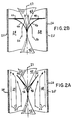
- FIGURES 2A and 2B Supported within the flue 16 is an elongated, thin, serpentine shaped baffle 42.
- the baffle 42 is disposed about the center-line 17 of the flue 16 and extends vertically along the length of the flue 16. Referring now to FIGURES 2A and 2B in conjunction with FIGURE 1, a short section of the flue 16 enclosing the serpentine baffle 42 is shown.
- Supported on opposite sides of the thin baffle 42 along its length are pairs of semi-circularly shaped fins 44.
- the fins 44 are individually secured to the baffle 42 by elongated, rectangularly shaped pieces 46 of bi-metallic material.
- the bi-metallic pieces 46 are formed so that when relatively hot gases from the main burner flow up the flue 16, the fins 44 retract away from the inner surface 18 of the flue 16 toward the baffle 42.
- the relatively hot gas flow is depicted by the arrows 52.
- the fins 44 direct the flow of hot gases outward toward the inner surface 18 of the flue 16.
- the fins 44 direct the hot gases toward the inner surface 18 of the flue 16 when maximum heat exchange is desired between the relatively hot gases within the flue 16 and water 21 surrounding the outer surface 20 of the flue 16.
- the bi-metallic pieces 46 are formed so that when relatively hot gases flowing up the flue 16 from the main burner subside (the main burner is off), the fins 44 extend horizontally outward from the baffle 42 toward the inner surface 18 of the flue 16. Disposed in this position away from the baffle 42, the semi-circularly shaped fins 44 are located immediately adjacent to the circularly shaped inner surface 18 of the flue 16. Thus disposed about the center-line 17 of the flue 16, the fins 44 direct any upward flow of gases (e.g. relatively cool gases from pilot flame and/or room air inwardly away from the inner surface 18 of the flue 16 and toward the baffle 42 as indicated by the arrows 56.
- gases e.g. relatively cool gases from pilot flame and/or room air
- the fins 44 obstruct the flow of gases along the inner surface 18 or the flue 16 thereby creating a stagnant layer of air along the inner surface 18 to, in effect, insulate the same.
- the fins 44 direct any flow of gases away from the inner surface or of the flue 16 when heat exchange between water 21 surrounding the outer surface 20 of the flue 16 and gases within the flue 16 is undesirable.
- a shape memory material such as nitinol (an alloy of nickel and titanium) could be used for the pieces 46.
- shape memory materials such as nitinol alter their shape in response to their temperature.
- the fins 44 would not be formed with a semi-circular shape. Rather they would be formed with a shape to mate with the interior surface of such a non-circularly shaped flue 16.
- the embodiment disclosed above includes a multiplicity of the moveable fins 44 disposed along the length of the flue.
- a number of benefits associated with the invention may be obtained if the moveable fins are not placed along the length of the flue.
- a pair of the moveable fins would be disposed at the top of the flue only or two of the moveable fins could be disposed at the top of the flue and two moveable fins could be disposed at the bottom of the flue.
Landscapes
- Engineering & Computer Science (AREA)
- Physics & Mathematics (AREA)
- Thermal Sciences (AREA)
- Mechanical Engineering (AREA)
- General Engineering & Computer Science (AREA)
- Chemical & Material Sciences (AREA)
- Combustion & Propulsion (AREA)
- Details Of Fluid Heaters (AREA)
- Heat-Pump Type And Storage Water Heaters (AREA)
- Instantaneous Water Boilers, Portable Hot-Water Supply Apparatuses, And Control Of Portable Hot-Water Supply Apparatuses (AREA)
Description
- The present invention relates generally to heat exchanging apparatus and, more particularly, to water heaters.
- The most common type of water heater presently in use consists of a storage tank for retaining heated water combined with some means for heating the water. Perhaps the most common means for heating the stored water is that in which a hot flame, produced by gas, for example, causes hot gases, including the combustion products, to rise through an elongated flue passing through the central portion of the storage tank. In this particular type of water heater the hot gases flowing up the flue contact its inner surface while the water within the storage tank is in contact with the flue's outer surface. While combustion continues, the water within the storage tank is heated by thermal conduction through the wall of the flue. In this type of water heater, an elongated baffle generally is disposed within the flue, about its center and along its length, to increase the efficiency of heat transfer from the hot gases through the wall of the flue to the water within the storage tank. Generally, this type of water heater includes a thermally activated valve that halts a combustion or main burner when the temperature of the water within the storage tank reaches a pre-established temperature.
- To reduce heat loss from the water heater both while the water is being heated and after combustion has been cut off, the exterior surface of the storage tank is typically covered with a thermal insulating material. However, the inner surface of the flue cannot be thermally insulated because it would inhibit heat transfer while the water is being treated. Unfortunately, once the water becomes heated and the main burner combustion stops, heat from the water is transferred back through the wall of the flue and heats the upwardly flowing air and gas within the flue associated with a pilot burner, for example, or induced air flow from the room area surrounding the heater. This heating of the air within the flue is a significant source of heat loss in water heaters and, consequently, reduces their efficiency and increases their operating cost.
- In most water heater installations, a vent pipe connects to the upper outlet of the flue outside of the water heater to conduct combustion products out of the building in which the heater is located. One technique for reducing heat loss from water heaters due to heating of the air within the flue during intervals when there is no combustion is the installation of a temperature responsive damper in this vent pipe. Examples of different types of such temperature responsive vent dampers are set forth in United States Patent Nos 3,197,139, 4,294,401, 4,337,892 and 4,384,671. However, because the flue's vent pipe must remain at least partially open for venting combustion products from the water heater's pilot which burns continuously whether or not water is being heated, the various devices disclosed in the preceding patents cannot completely block the flue's vent pipe to cut off all air and gas flowing through the flue.
- An object of the present invention is to provide increased efficiency in a gas water heater having a continuously burning pilot.
- Another object of the present invention is to reduce heat loss from a water heater during intervals in which water is not being heated.
- Another object of the present invention is to increase heat transfer to the water in a water heater's storage tank during intervals in which the water is being heated.
- Yet another object of the present invention is to provide a water heater that is cost effective in implementing the present invention.
- According to the present invention there is provided an apparatus for exchanging heat between a first fluid retained within said apparatus and a second fluid flowing through said apparatus, said apparatus comprising:
a storage tank for retaining the first fluid;
a flue means passing in heat exchange relationship with the first fluid in said storage tank, the first fluid being in heat transfer contact with a first surface of said flue means, and the second fluid flowing through said flue means being in heat transfer contact with a second surface thereof; and
flow control means having fins shaped so as to mate with the interior surface of said flue, for directing said second flowing fluid toward said second surface of said flue means when heat exchange is desired between the first and second fluids, and for directing said second flowing fluid inwardly away from said second surface of said flue means when heat exchange between the first and second fluids is undesirable. - Briefly, the preferred embodiment of the present invention comprises a water heater that includes flow control means for directing the flow of gas and air that pass through the water heater's flue. The means for controlling the flue flow directs hot gases flowing along the flue toward the flue's inner surface when heat transfer between those gases and the water is desired. The means for controlling the flow also directs the gas and all air within the flue away from the flue's inner surface when combustion is cut off and heat transfer is undesirable.
- In its preferred embodiment, the means for controlling the flow consists of a plurality of movable flow control fins secured at various locations along the length of the baffle supported within the flue. Each such fin is secured to the baffle by a piece of bi-metallic material whose shape of curvature changes in response to its temperature. These bi-metallic pieces are formed to position the fins near the middle of the flue along the baffle's length when hot gases are flowing through the flue. Thus disposed along the middle of the flue, the fins and bi-metallic pieces are adapted to direct the hot gases flowing through the flue toward the flue's inner surface. When there are not hot gases passing through the flue, the bi-metallic pieces position the fins near the flue's inner surface. Disposed adjacent to the flue's inner surface, the fins are adapted to direct any flow along the flue's length away from the flue's inner surface and to guide such flow along the baffle in the central portion of the flue.
- An advantage of the present invention is that it increases a water heater's operating efficiency.
- Another advantage is that it reduces a water heater's losses when water is not being heated.
- Another advantage is that it increases heat transfer into the water in a water heater's storage tank when heating is desired.
- Yet another advantage is that is reduces the cost of operating the water heater.
- Still another advantages when the burner is not firing is that it increases the thickness of the gas flow boundary layer at the inside surface of the flue wall when tends to provide an insulating effect.
- A further advantage when the burner is not firing is that the present invention adds a relatively large amount of restriction to the gas flow in order to limit the quantity of cool secondary air that flows through the flue.
- Yet a still further advantage when the burner is not firing is that an axial flow through the flue is promoted which, being away from the flue wall, minimizes the convective condition along the flue wall.
- These and other features, objects and advantages will be understood or apparent to those of ordinary skill in the art from the following detailed description of the preferred embodiment as illustrated in the various drawing figures.
- FIGURE 1 depicts a partially sectioned water heater in accordance with the present invention including its flow directing fins;
- FIGURE 2A is an enlargement of a portion of the water heater of FIGURE 1 depicting its flow directing fins disposed to increased heat exchange; and
- FIGURE 2B is an enlargement of the same portion of the water heater of FIGURE 1 as that of FIGURE 2A but depicting the flow directing fins disposed to reduce heat exchange.
- FIGURE 1 depicts a water heater in accordance with the present invention indicated by the
general reference character 10. Thewater heater 10 includes astorage tank 12 having a bottom head 14. A cylindricallyshaped flue 16 having a circular cross-sectional shape passes through the bottom head 14 and extends upward through thestorage tank 12. The bottom head 14 is formed with a downward concave shape to guide hot gases into theflue 16. Theflue 16 has a center-line 17 surrounded by aninner surface 18 which is contacted by gases within theflue 16. Theflue 16 also has anouter surface 20 surrounding the center-line 17 of theflue 16. Theouter surface 20 is contacted bywater 21 retained within thestorage tank 12. A conventional burner, not depicted in FIGURE 1, is located in the space immediately beneath the bottom head 14 for producing hot gases. Also not depicted in FIGURE 1, is a top head of thetank 12 through which theflue 16 also passes to project out of the top of thewater heater 10. Thus, theflue 16 passes completely through thestorage tank 12. - Immediately surrounding the sides and top of the
storage tank 12 is a layer ofinsulation 22. Anouter jacket 24 surrounds theinsulation 22 to protect it from mechanical damage. Threelegs 26 support thewater heater 10 on top of afloor 28. The cold and hot water connections to thewater heater 10 are not illustrated in FIGURE 1 since they may be entirely conventional and are not in themselves relevant to this invention. - A
draft hood 32 is supported above the top of theflue 16 by drafthood support legs 34. Projecting upward from the top or thedraft hood 32 is avent pipe 36. Thedraft hood 32 is formed with a downward concave shape to guide hot gases from theflue 16 into thevent pipe 36. Thedraft hood 32 is spaced above the top of thewater heater 10 and of theflue 16 so the hot gases from theflue 16 may entrain additional air to create a good draft up thevent pipe 36. - Supported within the
flue 16 is an elongated, thin, serpentine shapedbaffle 42. Thebaffle 42 is disposed about the center-line 17 of theflue 16 and extends vertically along the length of theflue 16. Referring now to FIGURES 2A and 2B in conjunction with FIGURE 1, a short section of theflue 16 enclosing theserpentine baffle 42 is shown. Supported on opposite sides of thethin baffle 42 along its length are pairs of semi-circularly shapedfins 44. Thefins 44 are individually secured to thebaffle 42 by elongated, rectangularly shapedpieces 46 of bi-metallic material. - As illustrated in FIGURE 2A, the
bi-metallic pieces 46 are formed so that when relatively hot gases from the main burner flow up theflue 16, thefins 44 retract away from theinner surface 18 of theflue 16 toward thebaffle 42. The relatively hot gas flow is depicted by thearrows 52. Thus disposed almost vertically along the center-line 17 of theflue 16, thefins 44 direct the flow of hot gases outward toward theinner surface 18 of theflue 16. Thus, thefins 44 direct the hot gases toward theinner surface 18 of theflue 16 when maximum heat exchange is desired between the relatively hot gases within theflue 16 andwater 21 surrounding theouter surface 20 of theflue 16. - As illustrated in FIGURE 2B, the
bi-metallic pieces 46 are formed so that when relatively hot gases flowing up theflue 16 from the main burner subside (the main burner is off), thefins 44 extend horizontally outward from thebaffle 42 toward theinner surface 18 of theflue 16. Disposed in this position away from thebaffle 42, the semi-circularly shapedfins 44 are located immediately adjacent to the circularly shapedinner surface 18 of theflue 16. Thus disposed about the center-line 17 of theflue 16, thefins 44 direct any upward flow of gases (e.g. relatively cool gases from pilot flame and/or room air inwardly away from theinner surface 18 of theflue 16 and toward thebaffle 42 as indicated by thearrows 56. Thus disposed, thefins 44 obstruct the flow of gases along theinner surface 18 or theflue 16 thereby creating a stagnant layer of air along theinner surface 18 to, in effect, insulate the same. Thus, thefins 44 direct any flow of gases away from the inner surface or of theflue 16 when heat exchange betweenwater 21 surrounding theouter surface 20 of theflue 16 and gases within theflue 16 is undesirable. - The effectiveness of the present invention has been tested by comparing the recovery efficiency, stand-by loss and energy factor among three
water heaters 10 respectively having: - 1. a
standard baffle 42 without anyfins 44; - 2. a
baffle 42 with only twofins 44 located near the top of theflue 16 to simulate the operation of the prior art temperature responsive vent dampers; and - 3. a
baffle 42 with twofins 44 located near the top or theflue 16, and 8 additional fins distributed along the length of thebaffle 42. - The following results were obtained for the preceding tests.

- While a bi-metallic material has been disclosed for the
pieces 46 that secure thefins 44 to thebaffle 42, a shape memory material such as nitinol (an alloy of nickel and titanium) could be used for thepieces 46. After proper forming and heat treating, similar to bi-metallic materials, shape memory materials such as nitinol alter their shape in response to their temperature. Similarly, for aflue 16 having a non-circular cross-sectional shape, thefins 44 would not be formed with a semi-circular shape. Rather they would be formed with a shape to mate with the interior surface of such a non-circularly shapedflue 16. - The embodiment disclosed above includes a multiplicity of the
moveable fins 44 disposed along the length of the flue. Of course, a number of benefits associated with the invention may be obtained if the moveable fins are not placed along the length of the flue. For example, a pair of the moveable fins would be disposed at the top of the flue only or two of the moveable fins could be disposed at the top of the flue and two moveable fins could be disposed at the bottom of the flue. In each case, varying degrees of improvement are recognized when the burner is not firing in regard to restricting or limiting the quantity of relatively cool secondary air which may flow through the flue while promoting axial flow through the flue to the extent that there is gas flow so as to minimize the convective condition along the flue wall. However, it is believed that the preferred embodiment disclosed is the most effective implementation of the present invention in regard to addressing all heat transfer aspects of the limited gas flow through the flue when the water heater burner is not firing.
Claims (12)
- An improved apparatus for exchanging heat between a first fluid (21) retained within said apparatus and a second fluid flowing through said apparatus, said apparatus comprising:
a storage tank (12) for retaining the first fluid (21);
a flue means (16) passing in heat exchange relationship with the first fluid (21) in said storage tank (12), the first fluid (21) being in heat transfer contact with a first surface (20) of said flue means (16), and the second fluid flowing through said flue means (16) being in heat transfer contact with a second surface thereof; and
flow control means (42) having fins (44) shaped so as to mate with the interior surface of said flue (16), for directing said second flowing fluid toward said second surface of said flue means (16) when heat exchange is desired between the first and second fluids, and for directing said second flowing fluid inwardly away from said second surface of said flue means (16) when heat exchange between the first and second fluids is undesirable. - The apparatus of Claim 1 further comprising means (22) for thermally insulating the outer surface of said storage tank (12).
- The apparatus of Claim 1 further comprising means for heating said second fluid prior to its flowing through said flue means (16).
- The apparatus of Claim 1 wherein said flow control means (42) comprises at least one moveable temperature responsive fin (44) for directing the flow of the second fluid.
- The apparatus of Claim 4 wherein said temperature responsive fin (44) moves toward the center of said flue means (16) when heat exchange is desired between said first and second flues, and moves away from the center of said flue means (16) when heat exchange between said first and second fluids is undesirable.
- The apparatus of Claim 4 further comprising a flow baffle supported within said flue means (16).
- The apparatus of Claim 6 wherein said temperature responsive fin (44) is secured to said flow baffle.
- The apparatus of Claim 7 wherein said temperature responsive fin (44) is secured to said flow baffle by a piece of material (46) whose shape changes in response to its temperature.
- The apparatus of Claim 8 wherein said piece of material (46) securing said temperature responsive fin (44) to said flow baffle is formed from a bi-metallic material.
- The apparatus of Claim 1 wherein said flow control means (42) comprises a plurality of moveable temperature responsive fins (44) for directing the flow of the second fluid in response to changes in the temperature of the second fluid, said fins (44) being disposed at least in either the upper or lower portions of said flue means (16).
- An improved method for exchanging heat between a first fluid retained within a storage tank (12), the storage tank (12) having a flue means (16) passing in heat exchange relationship therewith, and a second fluid, the method comprising the steps of:
contacting the first fluid retained in said storage tank (12) with a first surface of said flue means;
directing a flow of the second fluid through said flue means (16) so that the second fluid may contact a second surface of said flue means (16); and
directing the second flowing fluid toward said second surface of said flue means (16) when heat exchange is desired between the first and second fluids, and directing the second flowing fluid away from the second surface of said flue means (16) inwardly when heat exchange between the first and second fluids is undesirable. - The method of Claim 14 further comprising the step of heating the second fluid before said fluid passes through said flue means (16).
Applications Claiming Priority (2)
| Application Number | Priority Date | Filing Date | Title |
|---|---|---|---|
| US07/395,031 US4953510A (en) | 1989-08-17 | 1989-08-17 | Apparatus and method for heating water |
| US395031 | 1989-08-17 |
Publications (2)
| Publication Number | Publication Date |
|---|---|
| EP0413535A1 EP0413535A1 (en) | 1991-02-20 |
| EP0413535B1 true EP0413535B1 (en) | 1993-07-21 |
Family
ID=23561418
Family Applications (1)
| Application Number | Title | Priority Date | Filing Date |
|---|---|---|---|
| EP90308875A Expired - Lifetime EP0413535B1 (en) | 1989-08-17 | 1990-08-13 | Improved apparatus and method for heating water |
Country Status (4)
| Country | Link |
|---|---|
| US (1) | US4953510A (en) |
| EP (1) | EP0413535B1 (en) |
| CA (1) | CA2022121C (en) |
| DE (1) | DE69002288T2 (en) |
Families Citing this family (21)
| Publication number | Priority date | Publication date | Assignee | Title |
|---|---|---|---|---|
| GB2271834A (en) * | 1992-10-23 | 1994-04-27 | Nicholas Julian Jan F Macphail | Boiler |
| US5544625A (en) * | 1995-06-20 | 1996-08-13 | Giant Factories Inc. | Flue baffle for gas-fired hot water tanks |
| US5682841A (en) * | 1996-01-16 | 1997-11-04 | Schimmeyer; Werner K. | Variable flow volume control baffle and vent damper |
| US6286465B1 (en) | 2000-04-28 | 2001-09-11 | Aos Holding Company | Water heater flue system |
| US6422179B2 (en) | 2000-04-28 | 2002-07-23 | Aos Holding Company | Water heater flue system |
| US6557501B2 (en) | 2001-08-02 | 2003-05-06 | Aos Holding Company | Water heater having flue damper with airflow apparatus |
| US6584940B1 (en) | 2002-01-09 | 2003-07-01 | Therm-O-Disc, Incorporated | Flue pipe control |
| US6546897B1 (en) * | 2002-02-19 | 2003-04-15 | American Water Heater Company | Thermodynamically activated flue damper |
| DE10254202B4 (en) * | 2002-11-20 | 2006-05-18 | Siemens Ag | Device and method for detecting the seat occupancy in a vehicle |
| US6868806B1 (en) * | 2003-07-28 | 2005-03-22 | Vent damper apparatus | |
| DE102004006091B4 (en) * | 2004-02-07 | 2006-01-05 | Schott Ag | Gas-fired heating device |
| DE102004025223A1 (en) * | 2004-05-20 | 2005-12-15 | Schott Ag | Gas-fired water heater |
| DE102004034138B4 (en) * | 2004-07-15 | 2008-04-03 | Ceramat, S. Coop., Asteasu | Gas-fired heating device |
| DE102004041818B4 (en) * | 2004-08-27 | 2006-10-26 | Schott Ag | Gas-fired water heater |
| DE102004044445B4 (en) * | 2004-09-14 | 2008-07-24 | Ceramat, S. Coop., Asteasu | Gas-fired heating device |
| US7000572B1 (en) * | 2004-10-02 | 2006-02-21 | Schimmeyer Werner K | Telescopic baffle for water heater |
| US20070218776A1 (en) * | 2006-03-20 | 2007-09-20 | American Water Heater Company, A Corporation Of The State Of Nevade | Fuel supply line connector for water heater mounting bracket |
| US20070221142A1 (en) * | 2006-03-20 | 2007-09-27 | American Water Heater Company, A Corporation Of The State Of Nevada | Ultra low NOx water heater |
| CA2621525A1 (en) * | 2008-02-12 | 2009-08-12 | Claude Lesage | Flue baffle for gas-fired hot water tanks |
| US20090241858A1 (en) * | 2008-04-01 | 2009-10-01 | Aos Holding Company | Water heater with high efficiency baffles |
| US20090277399A1 (en) * | 2008-05-09 | 2009-11-12 | John Mezzalingua Associates, Inc. | Water heater and method of operating a waterheater |
Family Cites Families (8)
| Publication number | Priority date | Publication date | Assignee | Title |
|---|---|---|---|---|
| US600910A (en) * | 1898-03-22 | Heating device | ||
| US3170511A (en) * | 1961-03-27 | 1965-02-23 | Lyle D Guthrie | Stacked heat interchanger |
| US3492972A (en) * | 1967-09-12 | 1970-02-03 | Smith Corp A O | Hot water heater |
| DE2063066A1 (en) * | 1970-12-22 | 1972-07-13 | Brixa, Franz, Dipl.-Ing., 5800 Hagen | Turbulence insert for flue gas passes from heating boilers |
| US4157706A (en) * | 1978-04-28 | 1979-06-12 | Gaskill Emanuel P | Water heater |
| US4559998A (en) * | 1984-06-11 | 1985-12-24 | The Air Preheater Company, Inc. | Recuperative heat exchanger having radiation absorbing turbulator |
| US4850336A (en) * | 1987-06-16 | 1989-07-25 | Sankyo Manufacturing Company, Ltd. | Flue control device |
| US4817564A (en) * | 1988-03-21 | 1989-04-04 | A. O. Smith Corporation | Water heater construction |
-
1989
- 1989-08-17 US US07/395,031 patent/US4953510A/en not_active Expired - Lifetime
-
1990
- 1990-07-27 CA CA002022121A patent/CA2022121C/en not_active Expired - Fee Related
- 1990-08-13 EP EP90308875A patent/EP0413535B1/en not_active Expired - Lifetime
- 1990-08-13 DE DE90308875T patent/DE69002288T2/en not_active Expired - Fee Related
Also Published As
| Publication number | Publication date |
|---|---|
| US4953510A (en) | 1990-09-04 |
| DE69002288T2 (en) | 1993-11-04 |
| DE69002288D1 (en) | 1993-08-26 |
| EP0413535A1 (en) | 1991-02-20 |
| CA2022121C (en) | 1998-06-23 |
| CA2022121A1 (en) | 1991-02-18 |
Similar Documents
| Publication | Publication Date | Title |
|---|---|---|
| CA2022121C (en) | Apparatus and method for heating water | |
| US6736131B2 (en) | Gas fryer with improved heat-exchange properties | |
| US4147303A (en) | Heat-saving smoke pipe attachment | |
| US4084745A (en) | Waste heat utilization system | |
| US5228413A (en) | Multiple boiler | |
| EP0279765B1 (en) | Liquid-backed gas-fired heating system | |
| CA2047355A1 (en) | High efficiency water heater | |
| US4493308A (en) | Radiant/conductive broiler | |
| US4406402A (en) | Flue heat recovery system | |
| US4334518A (en) | Heating system | |
| US4747447A (en) | Heat exchanger | |
| US4904179A (en) | Low NOx primary zone radiant screen device | |
| EP0197212B1 (en) | Radiation shield, furnace and method for shielding a furnace convection section | |
| US2348127A (en) | Heat transfer and disseminating apparatus | |
| US1859745A (en) | Flue structure for heating apparatus | |
| US20060070618A1 (en) | Gas water heater damper/baffle | |
| US6584940B1 (en) | Flue pipe control | |
| US1959933A (en) | Water heating system | |
| US4149673A (en) | Self-pumping water boiler system | |
| GB2044441A (en) | Water heating arrangements in stoves | |
| US2335918A (en) | Water heater | |
| EP0773735A1 (en) | Frying device | |
| US2348834A (en) | Heating apparatus | |
| US4310746A (en) | Electric fluid heating apparatus | |
| US4090492A (en) | Forced air furnace with liquid heat exchanger |
Legal Events
| Date | Code | Title | Description |
|---|---|---|---|
| PUAI | Public reference made under article 153(3) epc to a published international application that has entered the european phase |
Free format text: ORIGINAL CODE: 0009012 |
|
| AK | Designated contracting states |
Kind code of ref document: A1 Designated state(s): DE FR GB IT NL |
|
| 17P | Request for examination filed |
Effective date: 19910424 |
|
| 17Q | First examination report despatched |
Effective date: 19910813 |
|
| GRAA | (expected) grant |
Free format text: ORIGINAL CODE: 0009210 |
|
| AK | Designated contracting states |
Kind code of ref document: B1 Designated state(s): DE FR GB IT NL |
|
| ITF | It: translation for a ep patent filed | ||
| REF | Corresponds to: |
Ref document number: 69002288 Country of ref document: DE Date of ref document: 19930826 |
|
| ET | Fr: translation filed | ||
| PLBE | No opposition filed within time limit |
Free format text: ORIGINAL CODE: 0009261 |
|
| STAA | Information on the status of an ep patent application or granted ep patent |
Free format text: STATUS: NO OPPOSITION FILED WITHIN TIME LIMIT |
|
| 26N | No opposition filed | ||
| PGFP | Annual fee paid to national office [announced via postgrant information from national office to epo] |
Ref country code: FR Payment date: 20010705 Year of fee payment: 12 |
|
| REG | Reference to a national code |
Ref country code: GB Ref legal event code: IF02 |
|
| PGFP | Annual fee paid to national office [announced via postgrant information from national office to epo] |
Ref country code: DE Payment date: 20020724 Year of fee payment: 13 |
|
| PG25 | Lapsed in a contracting state [announced via postgrant information from national office to epo] |
Ref country code: FR Free format text: LAPSE BECAUSE OF NON-PAYMENT OF DUE FEES Effective date: 20030430 |
|
| REG | Reference to a national code |
Ref country code: FR Ref legal event code: ST |
|
| PG25 | Lapsed in a contracting state [announced via postgrant information from national office to epo] |
Ref country code: DE Free format text: LAPSE BECAUSE OF NON-PAYMENT OF DUE FEES Effective date: 20040302 |
|
| PG25 | Lapsed in a contracting state [announced via postgrant information from national office to epo] |
Ref country code: IT Free format text: LAPSE BECAUSE OF NON-PAYMENT OF DUE FEES;WARNING: LAPSES OF ITALIAN PATENTS WITH EFFECTIVE DATE BEFORE 2007 MAY HAVE OCCURRED AT ANY TIME BEFORE 2007. THE CORRECT EFFECTIVE DATE MAY BE DIFFERENT FROM THE ONE RECORDED. Effective date: 20050813 |
|
| PGFP | Annual fee paid to national office [announced via postgrant information from national office to epo] |
Ref country code: GB Payment date: 20070830 Year of fee payment: 18 |
|
| PGFP | Annual fee paid to national office [announced via postgrant information from national office to epo] |
Ref country code: NL Payment date: 20070824 Year of fee payment: 18 |
|
| GBPC | Gb: european patent ceased through non-payment of renewal fee |
Effective date: 20080813 |
|
| NLV4 | Nl: lapsed or anulled due to non-payment of the annual fee |
Effective date: 20090301 |
|
| PG25 | Lapsed in a contracting state [announced via postgrant information from national office to epo] |
Ref country code: NL Free format text: LAPSE BECAUSE OF NON-PAYMENT OF DUE FEES Effective date: 20090301 |
|
| PG25 | Lapsed in a contracting state [announced via postgrant information from national office to epo] |
Ref country code: GB Free format text: LAPSE BECAUSE OF NON-PAYMENT OF DUE FEES Effective date: 20080813 |