EP0413128B1 - Ceramic orifice ring - Google Patents
Ceramic orifice ring Download PDFInfo
- Publication number
- EP0413128B1 EP0413128B1 EP90113089A EP90113089A EP0413128B1 EP 0413128 B1 EP0413128 B1 EP 0413128B1 EP 90113089 A EP90113089 A EP 90113089A EP 90113089 A EP90113089 A EP 90113089A EP 0413128 B1 EP0413128 B1 EP 0413128B1
- Authority
- EP
- European Patent Office
- Prior art keywords
- insert
- metal
- ring
- opening
- orifice
- Prior art date
- Legal status (The legal status is an assumption and is not a legal conclusion. Google has not performed a legal analysis and makes no representation as to the accuracy of the status listed.)
- Expired - Lifetime
Links
- 239000000919 ceramic Substances 0.000 title claims abstract description 32
- 229910052751 metal Inorganic materials 0.000 claims abstract description 43
- 239000002184 metal Substances 0.000 claims abstract description 43
- 239000006060 molten glass Substances 0.000 claims description 7
- 239000011521 glass Substances 0.000 claims description 6
- 229910010293 ceramic material Inorganic materials 0.000 claims description 2
- 229910045601 alloy Inorganic materials 0.000 abstract description 2
- 239000000956 alloy Substances 0.000 abstract description 2
- 239000010935 stainless steel Substances 0.000 description 4
- 229910001220 stainless steel Inorganic materials 0.000 description 4
- 239000000463 material Substances 0.000 description 3
- 238000007142 ring opening reaction Methods 0.000 description 3
- 229910000629 Rh alloy Inorganic materials 0.000 description 2
- 230000000694 effects Effects 0.000 description 2
- PXXKQOPKNFECSZ-UHFFFAOYSA-N platinum rhodium Chemical compound [Rh].[Pt] PXXKQOPKNFECSZ-UHFFFAOYSA-N 0.000 description 2
- VYZAMTAEIAYCRO-UHFFFAOYSA-N Chromium Chemical compound [Cr] VYZAMTAEIAYCRO-UHFFFAOYSA-N 0.000 description 1
- 229910000599 Cr alloy Inorganic materials 0.000 description 1
- 229910000990 Ni alloy Inorganic materials 0.000 description 1
- 229910018487 Ni—Cr Inorganic materials 0.000 description 1
- 239000000853 adhesive Substances 0.000 description 1
- 230000001070 adhesive effect Effects 0.000 description 1
- 239000004568 cement Substances 0.000 description 1
- 239000011651 chromium Substances 0.000 description 1
- 238000001816 cooling Methods 0.000 description 1
- 230000001627 detrimental effect Effects 0.000 description 1
- 230000003628 erosive effect Effects 0.000 description 1
- 238000004519 manufacturing process Methods 0.000 description 1
- 239000007769 metal material Substances 0.000 description 1
- 230000004048 modification Effects 0.000 description 1
- 238000012986 modification Methods 0.000 description 1
- 238000010943 off-gassing Methods 0.000 description 1
- 239000011214 refractory ceramic Substances 0.000 description 1
- 230000000717 retained effect Effects 0.000 description 1
- 238000006049 ring expansion reaction Methods 0.000 description 1
Images

Classifications
-
- C—CHEMISTRY; METALLURGY
- C03—GLASS; MINERAL OR SLAG WOOL
- C03B—MANUFACTURE, SHAPING, OR SUPPLEMENTARY PROCESSES
- C03B5/00—Melting in furnaces; Furnaces so far as specially adapted for glass manufacture
- C03B5/16—Special features of the melting process; Auxiliary means specially adapted for glass-melting furnaces
- C03B5/26—Outlets, e.g. drains, siphons; Overflows, e.g. for supplying the float tank, tweels
-
- C—CHEMISTRY; METALLURGY
- C03—GLASS; MINERAL OR SLAG WOOL
- C03B—MANUFACTURE, SHAPING, OR SUPPLEMENTARY PROCESSES
- C03B7/00—Distributors for the molten glass; Means for taking-off charges of molten glass; Producing the gob, e.g. controlling the gob shape, weight or delivery tact
- C03B7/08—Feeder spouts, e.g. gob feeders
- C03B7/088—Outlets, e.g. orifice rings
Definitions
- the present invention relates to a metal-lined ceramic orifice ring, especially for the outlet of a molten glass containing forehearth, and to a forehearth outlet device.
- US-A-2,433,116 discloses a platinum rhodium alloy liner for a continuous flow orifice through which molten glass for forming tubing is flowed.
- a metal clad, ceramic mandrel extends through the orifice member to serve as the former about which the molten glass flows in the production of glass tubing.
- the metal orifice liner or die appears to have its upper rim curled outwardly and downwardly with its outer rim extending into an annular space in the top of the ceramic orifice that is filled with a cement. The curled rim underlies extended wear and tends to warp due to thermal expansion.
- the present invention provides a metal insert for a ceramic ring which is designed to fit loosely in the opening from a horizontal dimension point of view, but is held in the opening by an annular threaded nut on the lower end of the insert.
- the insert is held by the threaded nut which has a specific upper sloping surface that engages the bottom of the ceramic ring to firmly hold the insert, but not crack the ring on thermal expansion.
- an orifice member 10 formed with a single opening 11 therein is counterbored at 12.
- the member 13 may be dropped in the opening 11 of the ring 10 and a lock nut 15 is threaded onto the lower end 17 of the metal ring 13.
- the upper surface 16 of the lock nut 15 is provided with a specific slope which takes into consideration the difference in thermal expansion characteristics of the metal insert ring and the ceramic orifice ring. During cold assembly the lock nut may be threaded onto the insert with the torque of a person's fingers.
- the slope of the upper surface 16 of the threaded lock nut 15 is calculated by the formula:
- an orifice ring 10 formed of Emhart 311 was counterbored to a 9.017 mm (0.375 inches) thickness with an orifice opening of 51.3 mm (2.02 inches).
- the metal ring 13 formed of stainless steel had an inside diameter of 44.45 mm (1.75 inches) and an outside diameter at the cylinder of 50.42 mm (1.985 inches).
- the threaded nut 15 had an outside diameter of 59.97 mm (2.361 inches).
- the flange 14 had an OD of 56.77 m (2.235 inches).
- a preferred metal for the insert is an alloy of nickel and chromium with about 50 % of each.
- the metal insert provides a glass feeder orifice that will retain its shape and size without change for an extended period of time. In the past, it was necessary to change ceramic orifices as frequently as every two or three weeks or 300 to 500 hours of use.
- the particular metal used as the insert material can be of any metal that can withstand temperatures in the 1150-1270°C (2100-230°F) range for an extended period without outgassing or changing shape.
- a more expansive metal that has been used at molten glass temperatures is platinum-rhodium alloys as suggestes in US-A-2,433,116.
- the important feature of the present invention is the use of a metal insert 13 that only embraces the small orifice opening 11 in a feeder orifice rather than lining the entire ceramic orifice member 10 with the ring held in place against the up and down movement that a feeder plunger may induce by having a lock nut 15 threaded onto the lower end 17 of the ring 13.
- the lock nut is provided with a slope to its upper surface 16 that engages the bottom 18 of the ceramic orifice. This slope is calculated so that during start-up of the feeder the expansion of the metal ring 13 and the expansion of the ceramic orifice 11 will be such that the nut 15 retains contact with the edge 19 of the bottom 18 of the orifice while the gap 20 between the insert 13 and orifice 11 disappears when operating temperatures are reached.
- the outside diameter R I of the metal insert 13 will have essentially the same diameter as the inside diameter of the ceramic orifice ring opening 11 and during warm-up the relative expansions are such that the nut 15 will retain the insert (13) in the orifice ring 10.
- the opening 21 may be made slightly larger than the size of the glass gob to be formed so that the proper size is maintained.
- the insert ring 13 After start-up, the insert ring 13 will be retained in its position as well and will experience very little wear.
Landscapes
- Chemical & Material Sciences (AREA)
- Engineering & Computer Science (AREA)
- Materials Engineering (AREA)
- Organic Chemistry (AREA)
- Furnace Charging Or Discharging (AREA)
- Ceramic Products (AREA)
- Special Chairs (AREA)
- Glass Compositions (AREA)
- Compositions Of Oxide Ceramics (AREA)
- Connection Of Plates (AREA)
Abstract
Description
- The present invention relates to a metal-lined ceramic orifice ring, especially for the outlet of a molten glass containing forehearth, and to a forehearth outlet device.
- In the past, forehearth outlets have been closed with ceramic rings that were lined with a metal sleeve such as disclosed in US-A-3,508,,904. In this patent a liner was formed of an inverted frusto-conical configuration mounted to cover the total inner surface of the orifice ring. Resistance to the erosive and corrosive effect of moving molten glass at elevated temperature is recited as one benefit of the metal liner. The metal orifice liner has its upper edge formed with a horizontal ledge that is, in effect, clamped between the upper surface of the orifice ring and the bottom surface of the feeder bowl. However, the metal and ceramic members show different thermal expansions that lead to undesired forces around the outlet.
- US-A-2,433,116 discloses a platinum rhodium alloy liner for a continuous flow orifice through which molten glass for forming tubing is flowed. A metal clad, ceramic mandrel extends through the orifice member to serve as the former about which the molten glass flows in the production of glass tubing. The metal orifice liner or die appears to have its upper rim curled outwardly and downwardly with its outer rim extending into an annular space in the top of the ceramic orifice that is filled with a cement. The curled rim underlies extended wear and tends to warp due to thermal expansion.
- It is an object of the present invention to provide a metal-lined ceramic orifice ring and a forehearth outlet device where the differences in thermal expansion do not show detrimental effects. This problem is solved according to the teaching of claims 1 and 4.
- The present invention provides a metal insert for a ceramic ring which is designed to fit loosely in the opening from a horizontal dimension point of view, but is held in the opening by an annular threaded nut on the lower end of the insert. The insert is held by the threaded nut which has a specific upper sloping surface that engages the bottom of the ceramic ring to firmly hold the insert, but not crack the ring on thermal expansion.
- Further details of the invention will be apparent from the following description taken in conjunction with the annexed sheet of drawings, in which
- Fig. 1
- is a vertical, sectional view through a feeder orifice member with a metal insert mounted therein, and
- Fig. 2
- is an enlarged cross-sectional view of the orifice area and metal insert of Fig. 1.
- In the past, efforts to make metal inserts for orifice members that are conventionally made of refractory ceramic materials has not been successful for various reasons.
- Three major problems which were encountered were:
the thermal expansion characteristics of the metal versus the ceramic were not properly considered;
roll pins that were used to hold inserts in place would not accomodate warp and would corrode long before the life of the insert had been realized.
The third problem was that prior attempts failed to take into consideration orifice ring handling and insert ring expansion during the start-up period, as well as during steady state operation. - While others have tried lining the entire orifice ring member with a metal material, this creates a gross thermal inbalance due to the increased cooling caused by the large metal area.
- When insert rings were held from below, metal members with large bottom flanges were needed and the heat radiating surface of these metal holders would detrimentally cool the inserts and result in an impeded glass flow. Further, it was common to try to hold inserts with adhesive or mud packs that would be subject to failure, particularly in an orifice structure that was used in a gob feeder with a reciprocating plunger.
- In view of the problems encountered in the past, it was found that a greatly simplified system for supporting a metal ring insert in the orifice ring was desirable.
- With reference to Fig. 1, an
orifice member 10 formed with a single opening 11 therein is counterbored at 12. Ametal insert ring 13 having ahorizontal flange 14 and an outside diameter somewhat smaller than the inside diameter of the orifice ring opening to avoid interference with thermal expansion of the ceramic orifice ring opening 11. - The
member 13 may be dropped in the opening 11 of thering 10 and alock nut 15 is threaded onto thelower end 17 of themetal ring 13. Theupper surface 16 of thelock nut 15 is provided with a specific slope which takes into consideration the difference in thermal expansion characteristics of the metal insert ring and the ceramic orifice ring. During cold assembly the lock nut may be threaded onto the insert with the torque of a person's fingers. - The slope of the
upper surface 16 of the threadedlock nut 15 is calculated by the formula: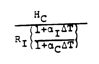
where - Hc
- is the thickness of the
bottom wall 18 ofmember 13 at the opening 11, - RI
- is the outside radius of
metal insert 13, - αI
- is the thermal expansion rate for the insert ring material,
- αc
- is the thermal expansion rate for the ceramic orifice material, and
- ΔT
- is the temperature above room temperature.
- The dimensions are indicated in Fig. 2 of the drawing. As a specific example, an
orifice ring 10 formed of Emhart 311 was counterbored to a 9.017 mm (0.375 inches) thickness with an orifice opening of 51.3 mm (2.02 inches). Themetal ring 13 formed of stainless steel had an inside diameter of 44.45 mm (1.75 inches) and an outside diameter at the cylinder of 50.42 mm (1.985 inches). The threadednut 15 had an outside diameter of 59.97 mm (2.361 inches). Theflange 14 had an OD of 56.77 m (2.235 inches). With this configuration a successful operation of feeding molten glass was carried out at a glass exit temperature of 1150°C (2100°F) for an extended period of time without failure of themetal ring 13. The expansion rate for the ceramic orifice ring at 1150°C (2100°F) was calculated to be 0.00808 mm/mm or inches per inch, and the stainless steel had an expansion rate of 0.02375 mm/mm or inch per inch. - While stainless steel has been used successfully, a preferred metal for the insert is an alloy of nickel and chromium with about 50 % of each.
- The use of a stainless steel insert resulted in an extended useful life of the feeder system to about 1000 hours. With the Ni-Cr alloy insert dimensioned as illustrated on the drawing, the feeder was operated for greater than 5000 hours, without appreciable change in the orifice integrity.
- The metal insert provides a glass feeder orifice that will retain its shape and size without change for an extended period of time. In the past, it was necessary to change ceramic orifices as frequently as every two or three weeks or 300 to 500 hours of use. The particular metal used as the insert material can be of any metal that can withstand temperatures in the 1150-1270°C (2100-230°F) range for an extended period without outgassing or changing shape. A more expansive metal that has been used at molten glass temperatures is platinum-rhodium alloys as suggestes in US-A-2,433,116.
- The important feature of the present invention is the use of a
metal insert 13 that only embraces the small orifice opening 11 in a feeder orifice rather than lining the entireceramic orifice member 10 with the ring held in place against the up and down movement that a feeder plunger may induce by having alock nut 15 threaded onto thelower end 17 of thering 13. The lock nut is provided with a slope to itsupper surface 16 that engages thebottom 18 of the ceramic orifice. This slope is calculated so that during start-up of the feeder the expansion of themetal ring 13 and the expansion of the ceramic orifice 11 will be such that thenut 15 retains contact with theedge 19 of thebottom 18 of the orifice while thegap 20 between theinsert 13 and orifice 11 disappears when operating temperatures are reached. Thus when the operating temperature is reached, the outside diameter RI of themetal insert 13 will have essentially the same diameter as the inside diameter of the ceramic orifice ring opening 11 and during warm-up the relative expansions are such that thenut 15 will retain the insert (13) in theorifice ring 10. - While some heat loss may be experienced by the use of a
metal insert ring 13, the opening 21 may be made slightly larger than the size of the glass gob to be formed so that the proper size is maintained. - After start-up, the
insert ring 13 will be retained in its position as well and will experience very little wear. - While the present disclosure is directed to the provision of a metal insert ring in a single orifice feeder, the use of the metal rings of the invention have been used in plural gob feeders with equal success. The ease of mounting and the foolproof operation during start-up and continuous use has made the inserts of the invention valuable, since changing orifice rings every two to three weeks is no longer necessary. It is believed that with the present invention the orifice rings used in feeders for long running jobs may not need changing for close to a year.
- Obvious modifications may be resorted to without departing from the scope of the claims.
Claims (4)
- A metal-lined ceramic orifice ring, especially for the outlet of a molten glass containing forehearth comprising
a ceramic ring (10) and a heat-resistant metal liner,
characterized in that
said liner is an insert (13) comprising a cylindrical metal body with external threads on the lower end (17) and a radially outwardly extending flange (14) at the upper end,
said ceramic ring (10) is bowl-shaped and has a bottom wall with an opening (11) extending therethrough for receiving, and being covered by, said insert (13) with the flange (14) overlying the opening (11) and the threaded end (17) extending below the bottom wall (18) of said ceramic ring (10),
said insert (13) is sized so as to fit in the covered opening (11) of said ceramic ring (10) with a predetermined annular gap (20) therebetween,
an internally threaded metal nut (15) is threaded onto the threaded end (17) of the insert (13), and is formed with an outwardly and downwardly sloped upper surface (16) contacting the bottom edge (19) of the covered opening (11), and
in that said sloped surface (16) has a slope matching the thermal expansion characteristics of the metal insert (13) and the ceramic ring (10). - The orifice ring of claim 1
wherein the slope of said sloped surface (16) is calculated by the formula: Hc is the height of the bottom wall (18) of the ceramic ring (10),RI is the outside radius of the cylindrical metal insert (13),αI is the thermal expansion rate for the metal insert (13),αc is the thermal expansion rate for the ceramic ring (10), andΔT is the temperature above room temperature.
 - The orifice ring of claim 1 or 2,
wherein said gap (20) formed by the internal diameter of said covered opening (11) and the external diameter (RI) of said insert (13) are chosen to allow for the differential thermal expansion of said ceramic ring (10) and said metal insert (13) with nut (15) such that said insert (13) will have the same outside diameter as the inside diameter of said covered opening (11) at operating temperature and said nut (15) will retain the insert (13) in said covered opening (11) during and after heat up to operating temperature. - A forehearth outlet device comprising
a glass feeder having a bottom wall of ceramic material with one or a plurality of openings therein,
characterized in that
each opening corresponds to said opening (11) as defined in any of claims 1 through 3 and
in that an insert (13) of heat-resistant metal for each opening (11) is provided in accordance with any of claims 1 through 3,
each said metal insert (13) defining an orifice (21) for the forehearth outlet device.
Priority Applications (1)
| Application Number | Priority Date | Filing Date | Title |
|---|---|---|---|
| AT90113089T ATE89244T1 (en) | 1989-08-18 | 1990-07-09 | CERAMIC OPENING RING. |
Applications Claiming Priority (2)
| Application Number | Priority Date | Filing Date | Title |
|---|---|---|---|
| US07/395,869 US4950321A (en) | 1989-08-18 | 1989-08-18 | Ceramic orifice ring |
| US395869 | 1999-09-14 |
Publications (2)
| Publication Number | Publication Date |
|---|---|
| EP0413128A1 EP0413128A1 (en) | 1991-02-20 |
| EP0413128B1 true EP0413128B1 (en) | 1993-05-12 |
Family
ID=23564884
Family Applications (1)
| Application Number | Title | Priority Date | Filing Date |
|---|---|---|---|
| EP90113089A Expired - Lifetime EP0413128B1 (en) | 1989-08-18 | 1990-07-09 | Ceramic orifice ring |
Country Status (7)
| Country | Link |
|---|---|
| US (1) | US4950321A (en) |
| EP (1) | EP0413128B1 (en) |
| JP (1) | JPH0383821A (en) |
| AT (1) | ATE89244T1 (en) |
| DE (1) | DE69001594T2 (en) |
| DK (1) | DK0413128T3 (en) |
| ES (1) | ES2040530T3 (en) |
Families Citing this family (9)
| Publication number | Priority date | Publication date | Assignee | Title |
|---|---|---|---|---|
| DE4202278C2 (en) * | 1992-01-28 | 1999-10-28 | Lindner Maschinen Gmbh W | Device for producing glass melt portions |
| JPH0630130U (en) * | 1992-05-18 | 1994-04-19 | 日本電気硝子株式会社 | Platinum well attachment structure to spout bottom |
| US5769920A (en) * | 1992-08-27 | 1998-06-23 | Union Oil Company Of California | Graphite guide rings |
| US5492552A (en) * | 1994-03-03 | 1996-02-20 | Minnesota Mining And Manufacturing Company | Holder for annealing fiber optic coils |
| US5609664A (en) * | 1995-05-17 | 1997-03-11 | Owens-Brockway Glass Container Inc. | Guide ring for I. S. glass forming machine |
| US6634187B1 (en) * | 2000-11-15 | 2003-10-21 | Owens-Brockway Glass Container Inc. | Apparatus for delivering a cased glass stream having a raised and sealed orifice bushing |
| US6656576B1 (en) | 2000-12-20 | 2003-12-02 | Owens Brockway Glass Container Inc. | Coated ceramic parts and method of fabricating same |
| DE10108831C1 (en) * | 2001-02-23 | 2002-06-13 | Omg Ag & Co Kg | Electrically heated feed nozzle for a glass melt used in the glass industry for melting and molding special glass comprises a cylindrical heating ring arranged coaxially around a cylindrical end piece made from platinum group metal material |
| US20240239699A1 (en) * | 2023-01-13 | 2024-07-18 | Owens-Brockway Glass Container Inc. | Orifice Ring Incorporating a MAX Phase Material |
Family Cites Families (7)
| Publication number | Priority date | Publication date | Assignee | Title |
|---|---|---|---|---|
| US1532514A (en) * | 1923-04-16 | 1925-04-07 | Illinois Pacific Glass Company | Plunger basin for glass-feeding boots |
| US2190296A (en) * | 1938-08-27 | 1940-02-13 | Westinghouse Electric & Mfg Co | Guide for molten material |
| US2276295A (en) * | 1940-06-14 | 1942-03-17 | Ferguson John | Electric glass melting furnace |
| US3393989A (en) * | 1964-12-10 | 1968-07-23 | Owens Illinois Glass Co | Hinged orifice ring holder for glass feeders |
| DE2200791A1 (en) * | 1971-01-27 | 1972-08-10 | Carborundum Co | Outlet nozzle for a melting furnace for the production of inorganic fibers |
| US4213002A (en) * | 1978-11-29 | 1980-07-15 | Sorg Gmbh & Co. Kg | Electrically heated melting furnace for mineral materials |
| CA1237580A (en) * | 1983-05-20 | 1988-06-07 | Owens-Illinois, Inc. | Glass feeder orifice ring and holder |
-
1989
- 1989-08-18 US US07/395,869 patent/US4950321A/en not_active Expired - Lifetime
-
1990
- 1990-07-09 AT AT90113089T patent/ATE89244T1/en not_active IP Right Cessation
- 1990-07-09 DE DE9090113089T patent/DE69001594T2/en not_active Expired - Fee Related
- 1990-07-09 EP EP90113089A patent/EP0413128B1/en not_active Expired - Lifetime
- 1990-07-09 ES ES199090113089T patent/ES2040530T3/en not_active Expired - Lifetime
- 1990-07-09 DK DK90113089.8T patent/DK0413128T3/en active
- 1990-07-13 JP JP2184430A patent/JPH0383821A/en active Granted
Also Published As
| Publication number | Publication date |
|---|---|
| DE69001594D1 (en) | 1993-06-17 |
| DK0413128T3 (en) | 1993-06-07 |
| ES2040530T3 (en) | 1993-10-16 |
| EP0413128A1 (en) | 1991-02-20 |
| JPH0520363B2 (en) | 1993-03-19 |
| US4950321A (en) | 1990-08-21 |
| DE69001594T2 (en) | 1993-08-19 |
| ATE89244T1 (en) | 1993-05-15 |
| JPH0383821A (en) | 1991-04-09 |
Similar Documents
| Publication | Publication Date | Title |
|---|---|---|
| US4950321A (en) | Ceramic orifice ring | |
| US2190296A (en) | Guide for molten material | |
| US5511593A (en) | Glass gob drop guide funnel assembly | |
| CA2214949C (en) | Method and apparatus for delivering a cased glass stream | |
| US20020089099A1 (en) | Molten metal holding furnace baffle/heater system | |
| CA1211939A (en) | Glass feeder heat baffle | |
| US3511306A (en) | Method and apparatus for centrifugally casting perforated rings | |
| US3134659A (en) | Glass melting apparatus and method useful for the production of glass fibers | |
| US3623857A (en) | Glass melting pot | |
| US1622666A (en) | Apparatus for feeding molten glass | |
| NO301257B1 (en) | Method and apparatus for producing self-baking carbon electrode | |
| US5865617A (en) | Replaceable nozzle for high temperature reactors having a fire-resistant lining | |
| EP0464740B1 (en) | Shotting apparatus and process | |
| US4754716A (en) | Refractory shield removable toe | |
| US4536202A (en) | Drain bushing | |
| JPH0248501B2 (en) | ||
| US20050286604A1 (en) | Electrode system for glass melting furnaces | |
| EP0201217B1 (en) | Heat shield for refractory tube in molten glass feeder | |
| CZ292248B6 (en) | Composite and monolithic refractory structure and process for producing thereof | |
| US4793849A (en) | Heat shield for refractory tube in molten glass feeder | |
| US3216815A (en) | Tapping nozzle for molten refractories | |
| US3187808A (en) | High temperature recuperator | |
| US4264300A (en) | Glassmaking tank furnace | |
| SU1379249A1 (en) | Glassmaking furnace outlet device | |
| RU2227822C1 (en) | Device for growing sapphire mono-crystals |
Legal Events
| Date | Code | Title | Description |
|---|---|---|---|
| PUAI | Public reference made under article 153(3) epc to a published international application that has entered the european phase |
Free format text: ORIGINAL CODE: 0009012 |
|
| AK | Designated contracting states |
Kind code of ref document: A1 Designated state(s): AT BE CH DE DK ES FR GB GR IT LI LU NL SE |
|
| 17P | Request for examination filed |
Effective date: 19901224 |
|
| 17Q | First examination report despatched |
Effective date: 19920422 |
|
| GRAA | (expected) grant |
Free format text: ORIGINAL CODE: 0009210 |
|
| ITF | It: translation for a ep patent filed | ||
| AK | Designated contracting states |
Kind code of ref document: B1 Designated state(s): AT BE CH DE DK ES FR GB GR IT LI LU NL SE |
|
| PG25 | Lapsed in a contracting state [announced via postgrant information from national office to epo] |
Ref country code: GR Free format text: LAPSE BECAUSE OF FAILURE TO SUBMIT A TRANSLATION OF THE DESCRIPTION OR TO PAY THE FEE WITHIN THE PRESCRIBED TIME-LIMIT Effective date: 19930512 |
|
| REF | Corresponds to: |
Ref document number: 89244 Country of ref document: AT Date of ref document: 19930515 Kind code of ref document: T |
|
| REG | Reference to a national code |
Ref country code: DK Ref legal event code: T3 |
|
| REF | Corresponds to: |
Ref document number: 69001594 Country of ref document: DE Date of ref document: 19930617 |
|
| ET | Fr: translation filed | ||
| REG | Reference to a national code |
Ref country code: ES Ref legal event code: FG2A Ref document number: 2040530 Country of ref document: ES Kind code of ref document: T3 |
|
| EPTA | Lu: last paid annual fee | ||
| EAL | Se: european patent in force in sweden |
Ref document number: 90113089.8 |
|
| PGFP | Annual fee paid to national office [announced via postgrant information from national office to epo] |
Ref country code: AT Payment date: 19950621 Year of fee payment: 6 |
|
| PG25 | Lapsed in a contracting state [announced via postgrant information from national office to epo] |
Ref country code: AT Effective date: 19960709 |
|
| REG | Reference to a national code |
Ref country code: GB Ref legal event code: IF02 |
|
| PGFP | Annual fee paid to national office [announced via postgrant information from national office to epo] |
Ref country code: LU Payment date: 20070705 Year of fee payment: 18 |
|
| PGFP | Annual fee paid to national office [announced via postgrant information from national office to epo] |
Ref country code: DK Payment date: 20080617 Year of fee payment: 19 |
|
| PGFP | Annual fee paid to national office [announced via postgrant information from national office to epo] |
Ref country code: CH Payment date: 20080708 Year of fee payment: 19 Ref country code: DE Payment date: 20080731 Year of fee payment: 19 Ref country code: ES Payment date: 20080715 Year of fee payment: 19 |
|
| PGFP | Annual fee paid to national office [announced via postgrant information from national office to epo] |
Ref country code: NL Payment date: 20080619 Year of fee payment: 19 Ref country code: IT Payment date: 20080718 Year of fee payment: 19 Ref country code: FR Payment date: 20080707 Year of fee payment: 19 |
|
| PGFP | Annual fee paid to national office [announced via postgrant information from national office to epo] |
Ref country code: GB Payment date: 20080616 Year of fee payment: 19 |
|
| PGFP | Annual fee paid to national office [announced via postgrant information from national office to epo] |
Ref country code: BE Payment date: 20080730 Year of fee payment: 19 Ref country code: SE Payment date: 20080708 Year of fee payment: 19 |
|
| BERE | Be: lapsed |
Owner name: *OWENS-BROCKWAY GLASS CONTAINER INC. Effective date: 20090731 |
|
| REG | Reference to a national code |
Ref country code: CH Ref legal event code: PL |
|
| REG | Reference to a national code |
Ref country code: DK Ref legal event code: EBP |
|
| EUG | Se: european patent has lapsed | ||
| GBPC | Gb: european patent ceased through non-payment of renewal fee |
Effective date: 20090709 |
|
| NLV4 | Nl: lapsed or anulled due to non-payment of the annual fee |
Effective date: 20100201 |
|
| REG | Reference to a national code |
Ref country code: FR Ref legal event code: ST Effective date: 20100331 |
|
| PG25 | Lapsed in a contracting state [announced via postgrant information from national office to epo] |
Ref country code: FR Free format text: LAPSE BECAUSE OF NON-PAYMENT OF DUE FEES Effective date: 20090731 Ref country code: LI Free format text: LAPSE BECAUSE OF NON-PAYMENT OF DUE FEES Effective date: 20090731 Ref country code: CH Free format text: LAPSE BECAUSE OF NON-PAYMENT OF DUE FEES Effective date: 20090731 |
|
| PG25 | Lapsed in a contracting state [announced via postgrant information from national office to epo] |
Ref country code: GB Free format text: LAPSE BECAUSE OF NON-PAYMENT OF DUE FEES Effective date: 20090709 |
|
| PG25 | Lapsed in a contracting state [announced via postgrant information from national office to epo] |
Ref country code: LU Free format text: LAPSE BECAUSE OF NON-PAYMENT OF DUE FEES Effective date: 20080709 Ref country code: DE Free format text: LAPSE BECAUSE OF NON-PAYMENT OF DUE FEES Effective date: 20100202 Ref country code: BE Free format text: LAPSE BECAUSE OF NON-PAYMENT OF DUE FEES Effective date: 20090731 |
|
| PG25 | Lapsed in a contracting state [announced via postgrant information from national office to epo] |
Ref country code: DK Free format text: LAPSE BECAUSE OF NON-PAYMENT OF DUE FEES Effective date: 20090731 |
|
| REG | Reference to a national code |
Ref country code: ES Ref legal event code: FD2A Effective date: 20090710 |
|
| PG25 | Lapsed in a contracting state [announced via postgrant information from national office to epo] |
Ref country code: ES Free format text: LAPSE BECAUSE OF NON-PAYMENT OF DUE FEES Effective date: 20090710 |
|
| PG25 | Lapsed in a contracting state [announced via postgrant information from national office to epo] |
Ref country code: IT Free format text: LAPSE BECAUSE OF NON-PAYMENT OF DUE FEES Effective date: 20090709 |
|
| PG25 | Lapsed in a contracting state [announced via postgrant information from national office to epo] |
Ref country code: SE Free format text: LAPSE BECAUSE OF NON-PAYMENT OF DUE FEES Effective date: 20090710 |
|
| PG25 | Lapsed in a contracting state [announced via postgrant information from national office to epo] |
Ref country code: NL Free format text: LAPSE BECAUSE OF NON-PAYMENT OF DUE FEES Effective date: 20100201 |
|
| PLBE | No opposition filed within time limit |
Free format text: ORIGINAL CODE: 0009261 |
|
| STAA | Information on the status of an ep patent application or granted ep patent |
Free format text: STATUS: NO OPPOSITION FILED WITHIN TIME LIMIT |