EP0413011B1 - Connecting device for toy building blocks - Google Patents
Connecting device for toy building blocks Download PDFInfo
- Publication number
- EP0413011B1 EP0413011B1 EP19900902995 EP90902995A EP0413011B1 EP 0413011 B1 EP0413011 B1 EP 0413011B1 EP 19900902995 EP19900902995 EP 19900902995 EP 90902995 A EP90902995 A EP 90902995A EP 0413011 B1 EP0413011 B1 EP 0413011B1
- Authority
- EP
- European Patent Office
- Prior art keywords
- bushing
- shaft
- stem
- parts
- shank
- Prior art date
- Legal status (The legal status is an assumption and is not a legal conclusion. Google has not performed a legal analysis and makes no representation as to the accuracy of the status listed.)
- Expired - Lifetime
Links
- 230000002093 peripheral effect Effects 0.000 claims description 3
- 238000007373 indentation Methods 0.000 claims 1
- 210000002105 tongue Anatomy 0.000 description 37
- 239000011324 bead Substances 0.000 description 5
- 238000006073 displacement reaction Methods 0.000 description 4
- 241000209035 Ilex Species 0.000 description 2
- 230000008878 coupling Effects 0.000 description 2
- 238000010168 coupling process Methods 0.000 description 2
- 238000005859 coupling reaction Methods 0.000 description 2
- 238000000034 method Methods 0.000 description 2
- 230000035508 accumulation Effects 0.000 description 1
- 238000009825 accumulation Methods 0.000 description 1
- 238000004873 anchoring Methods 0.000 description 1
- 230000004323 axial length Effects 0.000 description 1
- 238000005452 bending Methods 0.000 description 1
- 230000000903 blocking effect Effects 0.000 description 1
- 238000010276 construction Methods 0.000 description 1
- 230000006378 damage Effects 0.000 description 1
- 238000009826 distribution Methods 0.000 description 1
- 230000002401 inhibitory effect Effects 0.000 description 1
- 238000003780 insertion Methods 0.000 description 1
- 230000037431 insertion Effects 0.000 description 1
- 238000004519 manufacturing process Methods 0.000 description 1
- 239000000463 material Substances 0.000 description 1
- 230000005226 mechanical processes and functions Effects 0.000 description 1
- 238000003825 pressing Methods 0.000 description 1
Images


Classifications
-
- A—HUMAN NECESSITIES
- A63—SPORTS; GAMES; AMUSEMENTS
- A63H—TOYS, e.g. TOPS, DOLLS, HOOPS OR BUILDING BLOCKS
- A63H33/00—Other toys
- A63H33/04—Building blocks, strips, or similar building parts
-
- F—MECHANICAL ENGINEERING; LIGHTING; HEATING; WEAPONS; BLASTING
- F16—ENGINEERING ELEMENTS AND UNITS; GENERAL MEASURES FOR PRODUCING AND MAINTAINING EFFECTIVE FUNCTIONING OF MACHINES OR INSTALLATIONS; THERMAL INSULATION IN GENERAL
- F16B—DEVICES FOR FASTENING OR SECURING CONSTRUCTIONAL ELEMENTS OR MACHINE PARTS TOGETHER, e.g. NAILS, BOLTS, CIRCLIPS, CLAMPS, CLIPS OR WEDGES; JOINTS OR JOINTING
- F16B21/00—Means for preventing relative axial movement of a pin, spigot, shaft or the like and a member surrounding it; Stud-and-socket releasable fastenings
- F16B21/02—Releasable fastening devices locking by rotation
-
- F—MECHANICAL ENGINEERING; LIGHTING; HEATING; WEAPONS; BLASTING
- F16—ENGINEERING ELEMENTS AND UNITS; GENERAL MEASURES FOR PRODUCING AND MAINTAINING EFFECTIVE FUNCTIONING OF MACHINES OR INSTALLATIONS; THERMAL INSULATION IN GENERAL
- F16B—DEVICES FOR FASTENING OR SECURING CONSTRUCTIONAL ELEMENTS OR MACHINE PARTS TOGETHER, e.g. NAILS, BOLTS, CIRCLIPS, CLAMPS, CLIPS OR WEDGES; JOINTS OR JOINTING
- F16B21/00—Means for preventing relative axial movement of a pin, spigot, shaft or the like and a member surrounding it; Stud-and-socket releasable fastenings
- F16B21/10—Means for preventing relative axial movement of a pin, spigot, shaft or the like and a member surrounding it; Stud-and-socket releasable fastenings by separate parts
- F16B21/16—Means for preventing relative axial movement of a pin, spigot, shaft or the like and a member surrounding it; Stud-and-socket releasable fastenings by separate parts with grooves or notches in the pin or shaft
-
- F—MECHANICAL ENGINEERING; LIGHTING; HEATING; WEAPONS; BLASTING
- F16—ENGINEERING ELEMENTS AND UNITS; GENERAL MEASURES FOR PRODUCING AND MAINTAINING EFFECTIVE FUNCTIONING OF MACHINES OR INSTALLATIONS; THERMAL INSULATION IN GENERAL
- F16D—COUPLINGS FOR TRANSMITTING ROTATION; CLUTCHES; BRAKES
- F16D1/00—Couplings for rigidly connecting two coaxial shafts or other movable machine elements
- F16D1/10—Quick-acting couplings in which the parts are connected by simply bringing them together axially
- F16D1/108—Quick-acting couplings in which the parts are connected by simply bringing them together axially having retaining means rotating with the coupling and acting by interengaging parts, i.e. positive coupling
- F16D1/116—Quick-acting couplings in which the parts are connected by simply bringing them together axially having retaining means rotating with the coupling and acting by interengaging parts, i.e. positive coupling the interengaging parts including a continuous or interrupted circumferential groove in the surface of one of the coupling parts
Landscapes
- Engineering & Computer Science (AREA)
- General Engineering & Computer Science (AREA)
- Mechanical Engineering (AREA)
- Mutual Connection Of Rods And Tubes (AREA)
- Pivots And Pivotal Connections (AREA)
- Snaps, Bayonet Connections, Set Pins, And Snap Rings (AREA)
Abstract
Description
Die Erfindung betrifft eine Verbindungsvorrichtung für Spielzeug-Bauelemente, mit einem Schaft und einer auf den Schaft in dessen Längsrichtung aufschiebbaren Schaftbuchse, wobei der Schaft einen von der Kreisform abweichenden Querschnitt mit mehreren radial vorstehenden Querschnittsteilen hat, die aus Abschnitten einer Kreiszylinderfläche bestehende äussere Flächen haben, und die durch Zwischenbereiche kleineren Durchmessers voneinander getrennt sind, wobei der Schaft mit mehreren, in axialem Abstand voneinander angeordneten Quernuten versehen ist, in welche die Schaftbuchse zur Festlegung ihrer Längslage auf dem Schaft einrastbar ist. Eine solche Verbindungsvorrichtung ist aus der U.S. Patentschrift Nr. 3,638,352 bekannt. Diese bekannte Verbindungsvorrichtung umfasst einen aus Rad und Welle bestehenden Spielzeug-Bausatz, bei dem das Rad ein Radteil und ein Nabenteil aufweist, das über einen Flansch am Radteil befestigbar ist. Das Rad ist über ein Befestigungselement mit der Welle lösbar verbunden. Die Welle weist einen kreuzförmigen Querschnitt auf und ist mit Querrillen versehen, wobei das Rad- und Nabenteil mit je einem an den Querschnitt der Welle angepassten Passloch versehen ist. Das Befestigungselement ist als ein in eine Querrille der Welle eingreifender Federring ausgebildet, der in einer im Radteil vorgesehenen Vertiefung beweglich aufgenommen ist und durch das Nabenteil gehaltert ist. Der Flansch des Nabenteils ist über Kupplungszapfen mit dem Radteil befestig bar.The invention relates to a connecting device for toy components, with a shaft and a shaft bushing which can be pushed onto the shaft in its longitudinal direction, the shaft having a cross-section deviating from the circular shape with a plurality of radially projecting cross-sectional parts which have outer surfaces consisting of sections of a circular-cylindrical surface, and which are separated from one another by intermediate regions of smaller diameter, the shaft being provided with a plurality of transverse grooves which are arranged at an axial distance from one another and into which the shaft bushing can be snapped onto the shaft in order to fix its longitudinal position. Such a connecting device is known from US Pat. No. 3,638,352. This known connecting device comprises a toy kit consisting of wheel and shaft, in which the Wheel has a wheel part and a hub part which can be fastened to the wheel part via a flange. The wheel is detachably connected to the shaft via a fastening element. The shaft has a cross-shaped cross section and is provided with transverse grooves, the wheel and hub part each being provided with a fitting hole adapted to the cross section of the shaft. The fastening element is designed as a spring ring engaging in a transverse groove of the shaft, which is movably received in a recess provided in the wheel part and is held by the hub part. The flange of the hub part can be fastened to the wheel part via coupling pins.
Bei dieser bekannten Verbindungsvorrichtung kann ein Rad leicht und ohne Werkzeuge durch Aufschieben auf eine Welle auf dieser befestigt werden. Die Verbindung ist drehfest, nachteilig jedoch ist die begrenzt axiale Belastbarkeit des Rades.In this known connecting device, a wheel can be attached to a shaft easily and without tools by pushing it onto a shaft. The connection is non-rotatable, but the disadvantage is the limited axial load capacity of the wheel.
Aus der EP-A-0 273 863 ist eine weitere Verbindungsvorrichtung der eingangs genannten Art bekannt. Der Schaft hat hier zwei um 180° gegeneinander versetzte, radial vorstehende Querschnittsteile mit sägezahnförmigen Quernuten sowie Zwischenbereiche kleineren Durchmessers. Je auf einer Seite der radial vorstehenden Querschnittsteile erstreckt sich parallel zur Schaftachse eine radial abstehende Leiste. Die Schaftbuchse hat ebenfalls um 180° gegeneinander versetzte Bereiche mit sägezahnförmigen Nuten. Zwischen diesen Bereichen hat die Durchgangsöffnung einen Durchmesser, der dem Aussendurchmesser der radial vorstehenden Querschnittsteile des Schaftes entspricht. Die Buchse kann in der einen Drehstellung längs des Schaftes verschoben und durch Drehen um 90° axial starr mit dem Schaft verbunden werden. Dabei rasten die Leisten des Schaftes in entsprechende Längsnuten der Schaftbuchse ein, um ein ungewolltes Lösen der Verbindung zu verhindern. Diese bekannte Verbindungsvorrichtung eignet sich vor allem zur Befestigung von Lagerplatten eines Unterputz-Spülkastens. Eine in beiden Richtungen drehfeste Verbindung zwischen Schaft und Schaftbuchse ist durch diese Ausbildung nicht mgölich. Die Vorrichtung ist deshalb zur Verbindung von Spielzeugbauelementen ungeeignet.From EP-A-0 273 863 a further connection device of the type mentioned is known. The shank here has two radially projecting cross-sectional parts with a sawtooth-shaped transverse groove, offset by 180 ° to one another, and intermediate areas of smaller diameter. A radially projecting strip extends parallel to the shaft axis on each side of the radially projecting cross-sectional parts. The shaft bushing also has areas offset by 180 ° with sawtooth-shaped grooves. Between these areas, the through opening has a diameter which corresponds to the outer diameter of the radially projecting cross-sectional parts of the shaft. In one rotational position, the bushing can be displaced along the shaft and axially rigidly connected to the shaft by rotating it through 90 °. The strips of the shaft snap into corresponding longitudinal grooves in the shaft bushing in order to prevent the connection from being released unintentionally. This known connecting device is particularly suitable for fastening bearing plates of a concealed cistern. A connection between shaft and shaft bushing that is non-rotatable in both directions is not possible with this design. The device is therefore unsuitable for connecting toy components.
Aus der DE-C-1 026 134 ist eine Vorrichtung zur lösbaren Sicherung von Zahnrädern auf Keilwellen bekannt. Die Federn der Keilwelle sind benachbart ihrem axialen freien Ende durch eine Umfangsnut unterbrochen. Die Vorrichtung besteht aus zwei Ringen, die je eine Innenverzahnung entsprechend der Keilverzahnung der Keilwelle haben. Der eine Ring ist so breit wie die Umfangsnut.From DE-C-1 026 134 a device for releasably securing gears on spline shafts is known. The springs of the spline shaft are interrupted by a circumferential groove adjacent to their axial free end. The device consists of two rings, each with an internal toothing corresponding to the spline of the spline. One ring is as wide as the circumferential groove.
Die Ringe sind durch radiale Stifte im einen Ring, die in eine Umfangsnut des andern Rings ragen, miteinander verbunden. Die Ringe sind zwischen zwei Grenzstellungen gegeneinander verdrehbar und durch eine Feder in die erste Grenzstellung vorbelastet. In der ersten Grenzstellung sind die Innenverzahnungen der beiden Ringe gegeneinander versetzt, in der zweiten fluchten sie dagegen.The rings are connected to one another by radial pins in one ring, which protrude into a circumferential groove of the other ring. The rings can be rotated relative to one another between two limit positions and are preloaded into the first limit position by a spring. The internal gears are in the first limit position of the two rings offset against each other, in the second they are aligned.
Der Erfindung liegt die Aufgabe zugrunde, eine Verbindungsvorrichtung der eingangs genannten Art derart auszubilden, dass sie insbesondere zur Verbindung von Spielzeug-Bauelementen geeignet ist, eine rasche Montage ermöglicht und sowohl axial als auch in beiden Umfangsrichtungen eine sichere Verbindung schafft.The invention has for its object to provide a connecting device of the type mentioned in such a way that it is particularly suitable for connecting toy components, enables rapid assembly and creates a secure connection both axially and in both circumferential directions.
Diese Aufgabe wird dadurch gelöst, dass die Schaftbuchse aus einem ersten Buchsenteil und einem zweiten Buchsenteil besteht, dass die beiden Buchsenteile unverlierbar miteinander verbunden und gegeneinander zwischen einer Lösestellung, in welcher die Schaftbuchse axial längs des Schaftes verschiebbar ist und einer Sperrstellung bewegbar sind, in welcher mindestens ein einstückig angeformter Vorsprung in eine der Quernuten des Schaftes formschlüssig eingreift, dass zusammenwirkende Rastelemente am ersten und zweiten Buchsenteil vorhanden sind, welche zumindest in einer der Stellungen der beiden Buchsenteile einrasten, und dass mindestens eines der Buchsenteile eine dem Querschnitt des Schaftes angepasste Durchgangsöffnung zum drehfesten Eingriff mit dem Schaft aufweist.This object is achieved in that the shaft bushing consists of a first bushing part and a second bushing part, that the two bushing parts are captively connected to one another and to one another between a release position which the shaft bushing is axially displaceable along the shaft and a blocking position can be moved, in which at least one integrally molded projection engages in one of the transverse grooves of the shaft in a form-fitting manner, that cooperating locking elements are present on the first and second bushing parts, which are at least in one of the positions of the two Snap bushing parts into place, and that at least one of the bushing parts has a through opening adapted to the cross section of the shaft for non-rotatable engagement with the shaft.
Ausführungsbeispiele des Erfindungsgegenstandes werden nachstehend anhand der Zeichnungen erläutert. Es zeigen:
- Fig. 1
- eine perspektivische Ansicht eines Abschnitts einer ersten Ausführungsform eines Schaftes der erfindungsgemässen Verbindungsvorrichtung;
- Fig. 2
- eine Seitenansicht des Schaftes der Fig. 1,
- Fig. 3
- eine Stirnansicht des Schaftes der Fig. 1,
- Fig. 4 bis Fig. 8
- Halbschnitte des Schaftes der Fig. 1 mit einer darauf befindlichen erfindungsgemässen Schaftbuchse in verschiedenen Stellungen der Schaftbuchse bezüglich des Schaftes,
- Fig. 9
- eine Ansicht auf die eine Stirnseite eines Ausführungsbeispiels der erfindungsgemässen Schaftbuchse,
- Fig. 10
- einen Schnitt gemäss der Linie X-X in Fig. 9,
- Fig. 11
- einen Schnitt gemäss der Linie XI-XI in Fig. 9,
- Fig. 12
- eine Ansicht auf die andere Stirnseite der Schaftbuchse gemäss den Fig. 9 bis 11,
- Fig. 13
- eine perspektivische Ansicht auf die eine Stirnseite des einen Buchsenteils der Schaftbuchse der Fig. 9 bis 12,
- Fig. 14
- eine perspektivische Ansicht auf die andere Stirnseite des Buchsenteils der Fig. 13 in dazu um 90° verdrehter Lage bzw. auf die andere Stirnseite des anderen Buchsenteils der Schaftbuchse der Fig. 9 bis 12,
- Fig. 15
- eine perspektivische Ansicht auf eine aus den Buchsenteilen gemäss Fig. 13 und 14 zusammengesetzten Schaftbuchse in ausgezogener Relativlage ihrer beiden Buchsenteile;
- Fig. 16
- eine perspektivische Ansicht auf die Schaftbuchse der Fig. 15 in zusammengestossener Relativlage ihrer beiden Buchsenteile,
- Fig. 17
- eine perspektivische Ansicht einer zweiten Ausführungsform eines Schaftes der Verbindungsvorrichtung,
- Fig. 18
- eine Seitenansicht des Schaftes der Fig. 17,
- Fig. 19
- eine Stirnansicht des Schaftes der Fig. 17,
- Fig. 20
- eine perspektivische Ansicht einer Ausführungsform der erfindungsgemässen Verbindungsvorrichtung, bei welcher die Schaftbuchse mit einem axialen Verlängerungsansatz zur Aufnahme eines Schaftes versehen ist,
- Fig. 21
- eine perspektivische Ansicht einer als Schaftkupplung ausgebildeten Ausführungsform der erfindungsgemässen Verbindungsvorrichtung,
- Fig. 22 und Fig. 23
- perspektivische Ansichten eines ersten Buchsenteils einer weiteren Ausführungsform einer Schaftbuchse,
- Fig. 24 und Fig. 25
- perspektivische Ansichten eines zweiten Buchsenteils der Schaftbuchse,
- Fig. 26
- einen Axialschnitt durch die aus dem ersten Buchsenteil und dem zweiten Buchsenteil zusammengebaute Schaftbuchse,
- Fig. 27 und Fig. 28
- Stirnansichten der Schaftbuchse der Fig. 26 in der entriegelten und verriegelten Stellung, und
- Fig. 29 bis Fig. 32
- perspektivische Ansichten der Schaftbuchse der Fig. 26 in der verriegelten und entriegelten Stellung.
- Fig. 1
- a perspective view of a portion of a first embodiment of a shaft of the connecting device according to the invention;
- Fig. 2
- 2 shows a side view of the shaft of FIG. 1,
- Fig. 3
- 2 shows an end view of the shaft of FIG. 1,
- 4 to 8
- 1 with a shaft bushing according to the invention located thereon in different positions of the shaft bushing with respect to the shaft,
- Fig. 9
- 2 shows a view of one end face of an exemplary embodiment of the shaft bushing according to the invention,
- Fig. 10
- 4 shows a section along line XX in FIG. 9,
- Fig. 11
- 7 shows a section along the line XI-XI in FIG. 9,
- Fig. 12
- 9 shows a view of the other end face of the shaft bushing according to FIGS. 9 to 11,
- Fig. 13
- 3 shows a perspective view of the one end face of the one bushing part of the shaft bushing of FIGS. 9 to 12,
- Fig. 14
- 13 is a perspective view of the other end face of the bushing part of FIG. 13 in a position rotated by 90 °, or of the other end face of the other bushing part of the shaft bushing of FIGS. 9 to 12,
- Fig. 15
- a perspective view of a shaft bushing assembled from the bushing parts according to FIGS. 13 and 14 in the extended relative position of its two bushing parts;
- Fig. 16
- 15 shows a perspective view of the shaft bush of FIG. 15 in the collapsed relative position of its two bush parts,
- Fig. 17
- 2 shows a perspective view of a second embodiment of a shaft of the connecting device,
- Fig. 18
- 17 shows a side view of the shaft of FIG. 17,
- Fig. 19
- 17 shows an end view of the shaft of FIG. 17,
- Fig. 20
- 2 shows a perspective view of an embodiment of the connecting device according to the invention, in which the shaft bushing is provided with an axial extension for receiving a shaft,
- Fig. 21
- 2 shows a perspective view of an embodiment of the connecting device according to the invention designed as a shaft coupling,
- 22 and 23
- perspective views of a first bushing part of a further embodiment of a shaft bushing,
- 24 and 25
- perspective views of a second bushing part of the shaft bushing,
- Fig. 26
- an axial section through the shaft bushing assembled from the first bushing part and the second bushing part,
- 27 and 28
- End views of the shaft bushing of FIG. 26 in the unlocked and locked position, and
- 29 to 32
- perspective views of the shaft bushing of FIG. 26 in the locked and unlocked position.
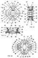
Der in den Fig. 1 bis 3 dargestellte Schaft 1 weist einen von der Kreisform abweichenden Querschnitt mit vier in der Art eines Kreuzes radial vorstehenden Querschnittsteilen 2 auf, die durch Zwischenbereiche 3 (Fig. 1, 3) kleineren Durchmessers in der Umfangsrichtung getrennt sind. Jeder Querschnittsteil 2 hat eine äussere Flache 4, welche durch einen Abschnitt einer Kreiszylinderfläche gebildet ist, so dass der Schaft 1 in ein kreisrundes Passloch eines Bauelementes steckbar ist. Der Schaft 1 ist zudem in gleichmässigen Abständen mit Quernuten 5 einheitlicher Breite B (Fig. 2) versehen. Im dargestellten Ausführungsbeispiel ist die Breite B der Quernuten 5 gleich gross wie die Breite der radial vorstehenden Querschnittsteile 2. Die Quernuten 5 weisen äussere Flächen 6 (Fig. 3) auf, die ebenfalls durch Abschnitte einer Kreiszylinderfläche mit einem Durchmesser D (Fig. 3) gebildet sind.The
In Fig. 4 sind in einem Längshalbschnitt ein Schaft 1 gemäss den Fig. 1 bis 3 und eine darauf aufgeschobene Schaftbuchse gemäss der Erfindung dargestellt. Die Schaftbuchse besteht hierbei aus zwei separaten, aber miteinander in Verbindung stehenden Buchsenteilen 7 und 8. Eine Gesamtdarstellung und weitere Einzelheiten der Buchsenteile 7 und 8 werden nachfolgend anhand der Fig. 9 bis 16 präsentiert.FIG. 4 shows a
Das eine Buchsenteil 7 weist eine vordere Stirnwand 9 auf, welche verständlicherweise mit einem aus Fig. 4 nicht näher ersichtlichen Ausschnitt mit der Form des Querschnitts des Schafts 1 der Fig. 1 und 3 versehen ist, so dass das Buchsenteil 7 auf dem Schaft 1 in dessen Längsrichtung verschiebbar ist. Die Stirnwand 9 ist mit einem äusseren Randwulst 10 versehen, der als Griffelement vorgesehen ist. An die Stirnwand 9 ist eine sich in axialer Richtung erstreckende Zunge 11 angeformt, welche demnach eine gewisse radiale Elastizität hat. Die Zunge 11 ist auf ihrer radial inneren Seite mit einem Nocken 12 und auf ihrer radial äusseren Seite mit einer nutartigen Vertiefung 13 versehen. Das Buchsenteil 7 weist zudem einen hülsenförmigen Abschnitt 14 mit einer rechteckigen Oeffnung 15 auf.One
Das Buchsenteil 8 hat ebenfalls eine äussere Stirnwand 16, welche einen nicht näher dargestellten, angepassten Ausschnitt für den Schaft 1 der Fig. 1 und 3 hat, so dass auch das Buchsenteil 8 auf dem Schaft 1 axial verschiebbar ist. Die Stirnwand 16 ist ebenfalls mit einem äusseren Randwulst 17 als Griffelement versehen. Ein sich von der Stirnwand 16 in Längsrichtung nach dem Innern des Buchsenteils 8 erstreckendes, an die Stirnwand 16 angeformtes Element 18 weist einen radial inneren Vorsprung 19 auf. Das Element 18 hat eine verhältnismässig grosse Wandstärke, so dass es im Gegensatz zur Zunge 11 des Buchsenteils 7 radial wenig elastisch ist. Vorzugsweise ist das Element 18 als Nocken eines hülsenförmigen Ansatzes (in Fig. 4 nicht näher dargestellt) der Stirnwand 16 ausgebildet. Dieser hülsenförmige Ansatz ist zudem mit einem zahnartigen, radial äusseren Vorsprung 20 versehen, der zufolge einer Ausnehmung eine geringe radiale Elastizität hat.The
Wie aus Fig. 4 ersichtlich ist, sind die Buchsenteile 7 und 8 der dargestellten Schaftbuchse innerhalb einer bestimmten Strecke ineinander verschiebbar, wobei das Buchsenteil 7 das äussere und das Buchsenteil 8 das innere Schiebeteil darstellen. Die relative Verschiebestrecke ist in der einen Richtung (der Stossrichtung) dadurch begrenzt, dass der Vorsprung 20 und die Innenfläche der Stirnwand 16 des Buchsenteils 8 zum Anliegen an das Buchsenteil 7 kommen. In der anderen Richtung (der Zugrichtung) ist die relative Verschiebestrecke dadurch begrenzt, dass der äussere Vorsprung 20 des Buchsenteils 8 am hülsenförmigen Abschnitt 14 des Buchsenteils 7 anschlägt.As can be seen from FIG. 4, the
Es ist somit aus Fig. 4 ersichtlich, dass die vorliegende Schafthülse, die aus den beiden gegenseitig axial verschiebbaren Buchsenteilen 7 und 8 zusammengesetzt ist, auf dem Schaft 1 durch Ausübung eines axialen Druckes auf den Randwulst 17 des Buchsenteils 8 in der Richtung des Pfeils 21 verschiebbar ist, indem der innere Vorsprung 19 des Buchsenteils 8 auf die Stirnfläche der Zunge 11 des Buchsenteils 7 drückt. Diese Verschiebebebewegung auf dem Schaft 1 erfolgt ohne grosse Kraftanstrengung. Der einzige mechanische Widerstand, der beim Aufschieben der Buchsenteile 7 und 8 auf den Schaft 1 zu überwinden ist, ist durch das elastische Ausbiegen der Zunge 11 des Buchsenteils 7 beim Ueberstreichen der äusseren Fläche 4 eines Querschnittsteils 2 des Schafts 1 verursacht, vgl. die Fig. 4.It can thus be seen from FIG. 4 that the present shaft sleeve, which is composed of the two axially
Bei Fortsetzung der Verschiebebewegung federt die Zunge 11 des Buchsenteils 7 in ihre Ruhelage zurück, wenn sie mit ihrem Nocken 12 über eine Quernut 5 des Schafts 1 zu liegen kommt, wie dies in Fig. 5 dargestellt ist. Somit kann die aus den Buchsenteilen 7 und 8 bestehende Schaftbuchse bis in eine bestimmte, gewünschte Axiallage über den Schaft 1 geschoben werden, wobei die in Fig. 5 dargestellten Zwischenpositionen durch leichtes Einrasten des Nockens 12 der Zunge 11 des Buchsenteils 7 in eine Quernut 5 des Schafts 1 für den Benützer jeweils spürbar und hörbar sind.When the displacement movement continues, the
Wenn die gewünschte Axiallage der Schaftbuchse auf dem Schaft 1 erreicht ist, also eine Lage gemäss Fig. 5, wird als nächster Schritt das Buchsenteil 7 auf dem Schaft 1 verriegelt. Hierzu wird einerseits eine weitere axiale Bewegung des Buchsenteils 7 in der Richtung des Pfeils 21 dadurch verhindert, dass das Buchsenteil 7 entweder von Hand festgehalten wird, oder dass das Buchsenteil 7 in der betreffenden Lage auf dem Schaft 1 mit seiner Stirnseite an ein anderes, ortsfestes Bauelement anschlägt. Diese beiden Möglichkeiten einer Bewegungshemmung sind in Fig. 6 durch eine gestrichelte Linie 22 angedeutet. Andererseits wird die Ausübung eines Drucks auf das Buchsenteil 8 in Richtung des Pfeils 21 fortgesetzt (Fig. 6). Dadurch drückt der innere Vorsprung 19 des Buchsenteils 8 den Nocken 12 der Zunge 11 des Buchsenteils 7 tiefer in die betreffende Quernut 5 hinein und rastet dann, wie aus Fig. 7 ersichtlich, in die nutartige Vertiefung 13 der Zunge 11 ein. Eine weitere axiale Bewegung des Buchsenteils 8 ist nicht mehr möglich, weil das Buchsenteil 8 mit seinem mit dem Vorsprung 20 versehenen Ende an der Innenseite der vorderen Stirnwand 9 des Buchsenteils 7 anliegt und weil das Buchsenteil 7 bezüglich des Schafts 1 unbeweglich ist, da der Nocken 12 seiner Zunge 11 vom Vorsprung 19 des Buchsenteils 8 in die Quernut 5 des Schafts 1 gedrückt ist.When the desired axial position of the shaft bushing on the
Somit ist die in Fig 7 dargestellte, die zusammengeschobenen Buchsenteile 7 und 8 umfassende Schaftbuchse gegen eine axiale Verschiebung auf dem Schaft 1 unter einem axialen Druck auf die Stirnseite des Buchsenteils 7 oder diejenige des Buchsenteils 8 absolut (das heisst bis zu einer mutwilligen Zerstörung der Buchsenteile) gesichert. Mittels einer oder mehrerer Schaftbuchsen gemäss Fig. 7 können demnach auf dem Schaft 1 beliebige Bauelemente, die ein Passloch für die Querschnittsteile 2 des Schafts 1 haben, in ihrer axialen Lage auf dem Schaft 1 durch eine einfache axiale Druckausübung auf das Buchsenteil 8 bezüglich des Buchsenteils 7 fest fixiert werden. Wie aus Fig. 7 ferner ersichtlich ist, beansprucht hierbei diese Schaftbuchse auf dem Schaft 1 eine axiale Länge von nur zwei je aus einem Querschnittsteil 2 und einer Quernut 5 bestehende Längeneinheiten des Schafts 1.Thus, the shaft bushing shown in FIG. 7, which comprises the pushed-together
Zum Lösen der verriegelten Schafthülse nach Fig. 7 und zum Abziehen der Schafthülse vom Schaft 1 wird der äussere Randwulst 17 des Buchsenteils 8 mit Fingern umfasst und in Richtung des Pfeils 23 in Fig. 7 gezogen. Da das Buchsenteil 7 mit seiner Zunge 11 auf dem Schaft 1 verankert ist, braucht es hierbei nicht festgehalten zu werden. Durch Ziehen des Buchsenteils 8 gleitet dessen Vorsprung 19 unter weiterer Versenkung des Nockens 12 der Zunge 11 des Buchsenteils 7 in die Quernut 5 aus der nutartigen Vertiefung 13 der Zunge 11, wie dies in umgekehrter Reihenfolge anhand der Fig. 6 bereits erläutert wurde. Durch weiteres Ziehen des Buchsenteils 8 in Richtung des Pfeils 23 in Fig. 8 gelangt die Schaftbuchse in den in Fig. 5 dargestellten Zustand, worauf gemäss Fig. 8 der äussere Vorsprung 20 des Buchsenteils 8 in der rechteckigen Oeffnung 15 des Abschnitts 14 des Buchsenteils 7 zum Anliegen an einen Rand der Oeffnung 15 kommt. Somit wird nun beim Abziehen des Buchsenteils 8 vom Schaft 1 in der Richtung des Pfeils 23 auch das Buchsenteil 7 mitgenommen.To release the locked shaft sleeve according to FIG. 7 and to pull the shaft sleeve off the
Eine besonders vorteilhafte Ausführungsform der anhand der Fig. 4 bis 8 mehr schematisch erläuterten, erfindungsgemässen Schaftbuchse wird nachstehend anhand der Fig. 9 bis 16 im einzelnen beschrieben. Die zu beschreibende Ausführungsform beruht auf der Erkenntnis, dass die in den Fig. 4 bis 8 dargestellten Buchsenteile 7 und 8, welche die Schaftbuchse bilden, identisch sein können und dadurch in der in den Fig. 4 bis 8 gezeigten Weise zusammengestellt und miteinander verbunden werden können, dass das eine der beiden identischen Buchsenteile gegenüber dem anderen um 90° gedreht wird. Dadurch lässt sich nicht nur eine vereinfachte Herstellung der Schaftbuchse mit nur einer Form, sondern auch eine noch bessere Verriegelung erzielen.A particularly advantageous embodiment of the shaft bushing according to the invention, which is explained more schematically with reference to FIGS. 4 to 8, is described in detail below with reference to FIGS. 9 to 16. The embodiment to be described is based on the knowledge that the
In den Fig. 9 und 12 sind Ansichten auf die beiden Stirnseiten des einzigen Buchsenteils 25 und in den Fig. 10 und 11 Schnitte durch das Buchsenteil 25 in zwei zueinander senkrechten Ebenen dargestellt. Wie bereits aus den Halbschnitten der Fig.4 bis 8 hervorgegangen ist, ist das Buchsenteil 25 axialsymmetrisch ausgebildet.FIGS. 9 and 12 show views of the two end faces of the
Das Buchsenteil 25 hat einen Flansch 26 und daran angeformte Hülsenabschnitte 27 und 28, die sich jeweils nur über Winkelbereiche von 90° erstrecken. In seinem Mittenbereich ist der Flansch 26 mit einer kreuzförmigen Oeffnung 29 versehen (Fig. 9, 12), in welche der Schaft 1 der Fig. 1 bis 3 derart passt, dass das Buchsenteil 25 auf den Schaft 1 aufgeschoben, auf diesem aber nicht verdreht werden kann.The
Der Flansch 26 und die daran angeformten Hülsenabschnitte 27 und 28 weisen Bereiche unterschiedlicher Form und Abmessungen auf. Wie insbesondere aus Fig. 9 ersichtlich ist, weist der Flansch 26 abwechselnd vier nach aussen kreisbogenförmig gekrümmte Randbereiche 30 und vier nach innen kreisbogenförmig gekrümmte Randbereiche 31 auf. Die nach aussen gekrümmten Randbereiche 30 des Flansches 26 sind mit einem axial und radial vorstehenden Randwulst 32 versehen (Fig. 10, 11). Auch die aus Fig. 12 ersichtlichen Hülsenabschnitte 27 und 28 setzen sich je aus einem nach aussen kreisförmig gekrümmten Abschnitt 33 bzw. 34 und beidseitig der Abschnitte 33, 34 aus einem nach innen kreisförmig gekrümmten Abschnitt 35 bzw. 36 zusammen. Hierbei sind die Hülsenabschnitte 28 gegenüber den Hülsenabschnitten 27 radial nach innen versetzt, schliessen aber mit ihren Aussenflächen direkt an die Innenflächen der Hülsenabschnitte 27 an.The
Aus Fig. 10 ist ersichtlich, dass die beiden Hülsenabschnitte 27 mit einer rechteckigen Oeffnung 37 versehen sind. Ferner ist im Winkelbereich der beiden Hülsenabschnitte 27 an den Flansch 26 je eine Zunge 38 angeformt, die sich in das Innere des Hülsenabschnitts 27 erstreckt. Die Zunge 38 ist vom Flansch 26 durch zwei spaltförmige Oeffnungen 39 getrennt (Fig. 9), so dass sich die Zunge 38 in beiden radialen Richtungen elastisch ausbiegen kann. Die Zunge 38 weist auf ihrer radial inneren Seiten einen abgerundeten Nocken 40 auf, dessen Länge in axialer Richtung gleich der Breite B der Quernuten 5 des Schafts 1 der Fig. 2 ist. Auf ihrer radial äusseren Seite ist die Zunge 38 mit einer nutartigen Vertiefung 41 versehen. Die auf dem Flansch 26 zwischen gegenüberliegenden spaltförmigen Oeffnungen 39 angeformten, gekrümmten Rippen 42 (Fig. 9) sind zur Verstärkung des Flansches 26 vorgesehen.10 that the two
Aus den Fig. 11 und 12 ist ersichtlich, dass die Hülsenabschnitte 28 mit je einem sich radial nach innen erstreckenden Nocken 43 versehen sind, der zudem einen inneren Vorsprung 44 aufweist, welcher der nutförmigen Vertiefung 41 der Zunge 38 entspricht. In seinem äusseren Endbereich ist jeder Hülsenabschnitt 28 darüberhinaus mit einem äusseren, zahnartigen Vorsprung 45 versehen. Die Nocken 43 sind am Flansch 26 angeformt (Fig. 10, 11) und von einer Oeffnung 46 umgeben. Dadurch erhalten die Nocken 43 eine gewisse radiale Elastizität, die aber kleiner als die radiale Elastizität der Zungen 38 ist. Die Bedeutung dieser radialen Elastizität der Nocken 43 wird nachstehend noch erläutert.11 and 12 that the
Es ist ersichtlich, dass die Schnittdarstellung des Buchsenteils 25 gemäss Fig. 10 bezüglich der geschnittenen Teile der Schnittdarstellung des Buchsenteils 7 in den Fig. 4 bis 8 entspricht. Ferner ist ersichtlich, dass die um 90° gedrehte Schnittdarstellung des Buchsenteils 25 gemäss Fig. 11 bezüglich der geschnittenen Teile der Schnittdarstellung des Buchsenteils 8 in den Fig. 4 bis 8 entspricht. Somit weist das Buchsenteil 25 sowohl die massgeblichen Funktionsteile des Buchsenteils 7 als auch diejenigen des Buchsenteils 8 der Fig. 4 bis 8 auf, und zwar in um 90° gedrehten, diametralen Lagen. Folglich können zwei identische Buchsenteile 25 gemäss den Fig. 9 bis 12 zur Verwirklichung der Schaftbuchse mit den Buchsenteilen 7 und 8 herangezogen werden, indem die beiden Buchsenteile 25 in einer um 90° relativ gedrehten Lage in axialer Richtung miteinander verbunden werden.It can be seen that the sectional view of the
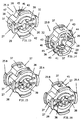
In den Fig. 13 bis 16 ist in perspektivischen Ansichten dieser Vorgang der Bildung einer erfindungsgemässen Schaftbuchse aus zwei Buchsenteilen 25 der Fig. 9 bis 12 dargestellt. In diesen Figuren ist das eine der identischen Buchsenteile mit 25 A und das andere mit 25 B bezeichnet.13 to 16, this process of forming a shaft bushing according to the invention from two
Das Buchsenteil 25 A entspricht der stirnseitigen Ansicht des Buchsenteils 25 gemäss Fig. 9, jedoch in einer um 90° gedrehten Lage bezüglich der Lage in Fig. 9 (Ansicht auf die Flanschseite). Das Buchsenteil 25 B entspricht der stirnseitigen Ansicht des Buchsenteils 25 gemäss Fig. 12 (Ansicht auf die offene Seite). Aus den Fig. 13 und 14 ist nun zu ersehen, dass das Buchsenteil 25 A (Fig. 13) mit seiner offenen Stirnseite 47 auf die offene Stirnseite 48 des Buchsenteils 25 B (Fig. 14) geschoben werden kann. Dies ist insbesondere deshalb ermöglicht, weil die Hülsenabschnitte 27 und 28 beider Buchsenteile 25 A und 25 B sowohl in radialer Richtung als auch in Umfangsrichtung derart aufeinander abgestimmt sind, so dass zwischen den Buchsenteilen 25 A und 25 B eine Art Schiebesitz vorliegt. Aus den Fig. 10 und 11 ist ferner ersichtlich, dass beim Aufschieben des Buchsenteils 25 A auf das Buchsenteil 25 B (bzw. umgekehrt) der zahnartige Vorsprung 45 beider Buchsenteile 25 A und 25 B in die radial gegenüberliegende Oeffnung 37 des jeweils anderen Buchsenteils einrastet, so dass die beiden Buchsenteile 25 A und 25 B nicht mehr voneinander trennbar, aber in axialer Richtung relativ verschiebbar sind, wie dies bereits anhand der Fig. 4 bis 8 erläutert worden ist.The socket part 25 A corresponds to the front view of the
In den Fig. 15 und 16 sind die beiden ineinander geschobenen Buchsenteile 25 A und 25 B perspektivisch dargestellt. Die Fig. 15 stellt die relative Lage der Buchsenteile 25 A und 25 B in einem auseinandergezogenen Zustand gemäss Fig. 4 dar, während in Fig. 16 der vollständig ineinander geschobene Zustand der Buchsenteile 25 A und 25 B entsprechend der Fig. 7 dargestellt ist. Aufgrund der vorgängigen Erläuterungen erübrigt sich deshalb eine weitere Beschreibung der Fig. 15 und 16. Aus den Fig. 15, 16 ist aber ersichtlich, dass die beiden Buchsenteile 25 A und 25 B mit ihren Hülsenabschnitten 27 und 28 (in Fig. 15, 16 ist nur der Hülsenabschnitt 27 sichtbar) sowohl in der Längsrichtung als auch in der Radialrichtung aneinander bzw. aufeinander gleiten können, wie dies auch aus Fig. 12 ersichtlich ist. Die Handhabung der miteinander untrennbar verbundenen, gegenseitig axial verschiebbaren und eine erfindungsgemässe Schaftbuchse bildenden Buchsenteile 25 A und 25 B ist demnach äusserst einfach und handgerecht, um die genannte Schaftbuchse auf einem Schaft 1 gemäss den Fig. 1 bis 3 zu verriegeln.15 and 16, the two nested parts 25 A and 25 B are shown in perspective. FIG. 15 shows the relative position of the socket parts 25 A and 25 B in an exploded state according to FIG. 4, while FIG. 16 shows the completely inserted state of the socket parts 25 A and 25 B according to FIG. 7. Due to the preceding explanations, a further description of FIGS. 15 and 16 is therefore unnecessary. From FIGS. 15, 16, however, it can be seen that the two socket parts 25 A and 25 B with their
Es ist insbesondere noch darauf hinzuweisen, dass die aus den ineinandergeschobenen Buchsenteilen 25 A und 25 B bestehende Schaftbuchse ingesamt vier Zungen 38 aufweist (in Fig. 15, 16 drei Zungen 38 sichtbar), denen je ein Nocken 43 zugeordnet ist (in Fig. 15, 16 keine Nocken 43 sichtbar), um die Zungen 38 in ein und derselben Quernut 5 des Schafts 1 (Fig. 1 bis 3) zu verriegeln, wenn die beiden Buchsenteile 25 A und 25 B bis zum Anschlag vollständig ineinander geschoben sind.In particular, it should also be pointed out that the shaft bushing consisting of the telescoped bush parts 25 A and 25 B has a total of four tongues 38 (three
Bei einem Verriegelungsvorgang, wie er vorgängig anhand der Fig. 4 bis 7 beschrieben worden ist bzw. bei einem anhand der Fig. 7 und 8 beschriebenen Entriegelungsvorgang muss bei einer Anwendung einer aus den Buchsenteilen 25 A und 25 B bestehenden Schaftbuchse ein besonderer Umstand in Betracht gezogen werden. Das zur Verriegelung auf den Schaft 1 geschobene Buchsenteil 25 A oder 25 B würde nämlich bei der Schiebebewegung mit seinen Zungen 38 an den Nocken 43 des anderen, stationären Buchsenteils 25 B bzw. 25 A fest und unbeweglich anstossen, da ja die Zungen 38 noch nicht in die Quernut 5 des Schafts 1 eingerastet sein können, sondern auf den äusseren Flächen 4 des vorangehenden Querschnittsteils 2 aufliegen und demnach radial nach innen unbeweglich sind. Um eine solche unerwünschte und die Verriegelung verhindernde Arretierung der Schiebebewegung zu verhindern, weisen die Nocken 43, wie bereits erwähnt, eine gewisse radiale Elastizität auf, so dass sie beim Schiebevorgang über die Zungen 38 des eingeschobenen Buchsenteils gleiten können. Die radiale Elastizität der Nocken 43 ist jedoch nicht so gross wie diejenige der Zungen 38, so dass die Zungen 38 des eingeschobenen Buchsenteils durch die Nocken 43 des stationären Buchsenteils in die Quernut 5 gedrückt werden, in welche die Zungen 38 des stationären Buchsenteils bereits eingerastet sind.In the case of a locking operation as described above with reference to FIGS. 4 to 7 or in an unlocking operation described with reference to FIGS. 7 and 8, a special circumstance must be taken into account when using a shaft bushing consisting of the
Da die bisher beschriebene, aus den Buchsenteilen 7 und 8 bzw. 25 A und 25 B bestehende Schaftbuchse in ihrem Aufbau einzig von der Querschnittsform des vorgesehenen Schafts abhängig ist, kann ohne weiteres eingesehen werden, dass gegebenenfalls andere Querschnittsformen des Schafts durch geringfügige Aenderungen des Buchsenteils 25 der Fig. 9 bis 12 berücksichtigt werden können. Massgebend ist hierbei die Form der Oeffnung 29 des Flansches 26 (Fig. 9, 12), welche der Querschnittsform des vorgesehenen Schafts zu entsprechen hat,wobei vorausgesetzt ist, dass der Schaftquerschnitt bezüglich seiner Querschnittsteile axialsymmetrisch ausgebildet ist, also insbesondere vier um je 90° versetzte, identische Querschnittsteile hat. Somit sind auch andere Schaftausbildungen gemäss den Fig. 17 bis 19 für die erfindungsgemässe Verbindungsvorrichtung beispielsweise in Betracht zu ziehen.Since the shaft bushing described so far, consisting of the
In den Fig. 17 bis 19 ist ein Schaft 49 dargestellt, der ebenfalls einen von der Kreisform abweichenden Querschnitt aufweist, welcher hier im wesentlichen die Form eines Vierecks, insbesondere eines Quadrats hat, dessen Ecken abgeflacht bzw. abgerundet sind und äussere Flächen 4 haben, die wiederum durch Abschnitte einer Kreiszylinderfläche gebildet sind. In gleichmässigen Abständen zwischen den Querschnittsteilen 2 ist der Schaft 49 mit den bereits beschriebenen Quernuten 5 versehen. Eine für den Schaft 49 vorgesehene Schaftbuchse setzt sich aus zwei Buchsenteilen ähnlich den Buchsenteilen 25 A und 25 B in Fig. 15 und 16 zusammen, wobei jedoch die mittige Oeffnung der beiden Buchsenteile in Abweichung von der Oeffnung 29 der Fig. 12 eine dem Querschnitt des Schafts 49 nach Fig. 19 entsprechende Form hat. Zudem muss selbstverständlich die radiale Ruhelage der beiden Zungen 11 (Fig. 4 bis 8) bzw. der vier Zungen 38 (Fig. 9 bis 12) auf den Durchmesser der äusseren Flächen 4 des Schafts 49 der Fig. 17 bis 19 abgestimmt sein, oder umgekehrt. Dann ist die Funktion der entsprechend modifizierten, nicht dargestellten Schafthülse auf dem Schaft 49 der Fig. 17 bis 19 die gleiche wie diejenige der aus den miteinander verbundenen Buchsenteilen 25 A und 25 B bestehenden Schafthülse der Fig. 13 bis 16 auf dem Schaft 1 der Fig.1 bis 3.17 to 19 show a
Bei dem in Fig. 20 dargestellten Ausführungsbeispiel der aus den ineinandergreifenden Buchsenteilen 25 A und 25 B bestehenden Schaftbuchse (vgl. auch die Fig. 15 und 16) ist das eine Buchsenteil 25 A an seinem Flansch 26 (vgl. Fig. 9) mit einem axialen Verlängerungsansatz 50 versehen, der an den Flansch 26 angeformt ist. Der Ansatz 50 weist eine axiale Durchgangsöffnung 51 auf, deren Querschnitt genau der kreuzförmigen Oeffnung 29 des in Fig. 9 dargestellten Buchsenteils 25 entspricht und deshalb zur Aufnahme eines Schafts 1 gemäss Fig. 1 ausgebildet ist. Wenn demnach die Schaftbuchse 25 A / 25 B der Fig. 20 auf einem Schaft 1 gemäss Fig. 1 in der vorbeschriebenen Weise verankert ist, kann in das offene Ende des Ansatzes 50 ein weiterer Schaft gemäss Fig. 1 gesteckt werden. In Fig. 20 ist die Endfläche 52 des offenen Endes des Ansatzes 50 gestrichelt dargestellt, um anzudeuten, dass der Ansatz 50 eine beliebige Länge haben kann. Durch die gestrichelte Darstellung der Endfläche 52 wird ferner angedeutet, dass an die Endfläche 52 weitere Verbindungselemente (nicht dargestellt) angeformt sein können, welche eine Verbindung des Ansatzes 50 und damit der Schaftbuchse 25 A / 25 B mit einem anderen Bauelement entweder in koaxialer Richtung zum Ansatz 50 oder in zum Ansatz 50 senkrechter Richtung erlauben. Die auf der Aussenseite des Ansatzes 50 dargestellten Längsausnehmungen 53 haben keine mechanische Funktion, sondern dienen nur einer Verminderung unnötiger Materialansammlungen.In the exemplary embodiment shown in FIG. 20, the shaft bushing consisting of the interlocking bush parts 25 A and 25 B (see also FIGS. 15 and 16) is a bush part 25 A on its flange 26 (see FIG. 9) with a provided
Bei der Ausführungsform der Fig. 20 ist ein in den Ansatz 50 gesteckter Schaft (nicht dargestellt) in der einen oder anderen Drehrichtung mit dem Schaft, auf welchem die Schaftbuchse 25 A / 25 B verankert ist, fest verbunden, dagegen offensichtlich nicht in axialer Richtung. Um eine in jeder Richtung starre, lösbare Verbindungsvorrichtung zweier Schäfte 1 gemäss Fig 1 zu erzielen, wird gemäss Fig. 21 die Massnahme vorgesehen, die Endfläche 52 des Ansatzes 50 der Fig. 20 an den stirnseitigen Flansch 26 entsprechend Fig. 9 eines weiteren Buchsenteils 25 C fest anzuformen, das gleich ausgebildet ist wie das in Fig. 9 dargestellte Buchsenteil 25, und das in Verbindung mit einem mit ihm zusammengesteckten, identischen Buchsenteil 25 D eine zweite Schaftbuchse bildet, welche mit der Schaftbuchse 25 A / 25 B übereinstimmt. Die eine Schaftbuchse 25 A / 25 B wird demnach auf dem Endbereich eines ersten Schafts und die Schaftbuchse 25 C / 25 D auf dem Endbereich eines zweiten Schafts verankert, wobei der Ansatz 50 allenfalls vorstehende Enden der Schäfte aufnimmt. Da die Verankerung jeder Schaftbuchse 25 A / 25 B bzw. 25 C / 25 D auf ihrem Schaft sowohl in Drehrichtung als auch in axialer Richtung fest ist, ergibt sich eine entsprechend feste Verbindung der beiden Schäfte.In the embodiment of FIG. 20, a shaft (not shown) inserted into the
Anhand der Fig. 15 und 16 ist eine erfindungsgemässe Schaftbuchse beschrieben worden, welche sich aus zwei identischen, ineinander geschobenen Buchsenteilen 25 A und 25 B zusammensetzt. Jedes Buchsenteil 25 A, 25 B weist hierbei in diametraler Anordnung zwei Zungen 38 und zwei Nocken 43 auf. Damit die Nocken 43 des jeweils einen Buchsenteils auf die Zungen 38 des jeweils andern Buchsenteils einwirken können, werden die beiden Buchsenteile 25 A, 25 B in um 90° gegenseitig gedrehter Lage zusammengesetzt. Das gleiche Prinzip lässt sich bei entsprechender Grösse der Buchsenteile auch mit einer höheren, durch zwei teilbaren Anzahl von Zungen und Nocken in jeweils diametraler Anordnung in jedem Buchsenteil anwenden, beispielsweise mit vier Zungen und Nocken in jedem Buchsenteil.A shaft bushing according to the invention has been described with reference to FIGS. 15 and 16, which is composed of two identical bush parts 25 A and 25 B pushed into one another. Each socket part 25 A, 25 B has two
Es ist aber auch möglich, eine Dreierteilung vorzusehen, indem jedes Buchsenteil drei in Winkelbereichen von 120° angeordnete Zungen und dazwischen drei ebenfalls in Winkelbereichen von 120° angeordnete Nocken aufweist. Die beiden identischen Buchsenteile dieser Art werden dann in um 60° gegeneinander gedrehter Winkellage durch Ineinanderschieben zusammengesetzt. Hierbei müssen selbstverständlich auch die übrigen Partien dieser Buchsenteile, wie die Hülsenabschnitte 27 und 28, die Oeffnungen 37 und die Vorsprünge 45 des in den Fig. 9 bis 12 dargestellten Buchsenteils 25, der vorgesehenen Dreierteilung angepasst werden. Ferner muss der zugehörige Schaft eine Symmetrie bezüglich einer Winkellage von 60° aufweisen.However, it is also possible to provide a division into three, in that each socket part has three tongues arranged in angular ranges of 120 ° and in between three cams also arranged in angular ranges of 120 °. The two identical socket parts of this type are then assembled in an angular position rotated by 60 ° relative to one another by pushing one into the other. Here, of course, the other parts of these socket parts, such as the
Bei den in Fig. 4-16 gezeigten Ausführungsbeispielen werden die Buchsenteile 7, 8 zur Sicherung axial gegeneinander verschoben. Es ist jedoch auch möglich, die Sicherung durch ein Verdrehen der beiden Buchsenteile gegeneinander zu verwirklichen. Die beiden Buchsenteile können in diesem Fall nicht identisch ausgebildet werden, sondern das sichernde Buchsenteil muss gegenüber dem Schaft 1 verdrehbar sein und deshalb eine zylindrische Durchgangsbohrung aufweisen. Im Unterschied zu den zuvor beschriebenen Ausführungsformen braucht dann das die federnde Zunge 11 mit dem Nocken 12 übergreifende Sicherungselement nicht radial federnd zu sein. Damit kann eine stärker belastbare axiale Sicherung trotz kleinerem Kraftaufwand für die Sicherungsbewegung erzielt werden.In the exemplary embodiments shown in FIGS. 4-16, the
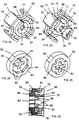
In den Fig. 22 bis 32 ist eine weitere Ausführungsform einer erfindungsgemässen Schaftbuchse 60 dargestellt, welche durch eine Drehbewegung von zwei Buchsenteilen 61, 62 gegeneinander zwischen einer Lösestellung, in welcher die Schaftbuchse längs des Schaftes 1 (Fig. 1-3) axial verschiebbar ist, und einer Sperrstellung beweglich sind, in welchen radiale Vorsprünge in die Quernuten 5 des Schaftes 1 formschlüssig eingreifen.
Das erste Buchsenteil 61 (Fig. 22 und 23) besteht aus einer Hülse 63 und einem über drei Stege 64 einstückig daran angeformten Drehglied 65. Die Hülse 63 hat einen durchgehenden Längsschlitz 66 und eine zylindrische Innenfläche 67, deren Durchmesser dem Durchmesser der äusseren Fläche 4 des Schaftes 1 entspricht. Von der Innenfläche 67 ragen vier radiale Vorsprünge 68 nach innen zum Eingriff in die Quernuten 5 des Schaftes 1. Diese Vorsprünge 68 sind wie folgt ausgebildet:
- In Umfangsrichtung sind die radialen Vorsprünge 68 gleichmässig verteilt, hier also in Winkelabständen von 90°;
- die Breite jedes Vorsprungs 68 in der Achsrichtung der Hülse 63 ist höchstens gleich der Breite
B der Quernuten 5 des Schaftes 1 (Fig. 2); - die
Vorsprünge 68 weisen kreiszylindrische Innenflächen 69 auf, deren Durchmesser mindestens gleich dem Durchmesser D derQuernuten 5 des Schaftes 1 (Fig. 3) ist; - die Abmessung jedes Vorsprungs 68 in
Umfangsrichtung der Hülse 63 ist höchstens gleich der Abmessung inUmfangsrichtung der Zwischenbereiche 3 des Schaftes 1 (Fig. 3); und - zur Erleichterung des Einfahrens in
die Quernuten 5 desSchaftes 1 haben dieVorsprünge 68 in Umfangsrichtung betrachtet beidseitig keilförmige Anschrägungen 70.
The first socket part 61 (FIGS. 22 and 23) consists of a
- The
radial projections 68 are evenly distributed in the circumferential direction, here at 90 ° angular intervals; - the width of each
projection 68 in the axial direction of thesleeve 63 is at most equal to the width B of thetransverse grooves 5 of the shaft 1 (FIG. 2); - the
projections 68 have circular cylindricalinner surfaces 69, the diameter of which is at least equal to the diameter D of thetransverse grooves 5 of the shaft 1 (FIG. 3); - the dimension of each
projection 68 in the circumferential direction of thesleeve 63 is at most equal to the dimension in the circumferential direction of theintermediate regions 3 of the shaft 1 (FIG. 3); and - In order to facilitate insertion into the
transverse grooves 5 of theshaft 1, theprojections 68 have beveledchamfers 70 on both sides when viewed in the circumferential direction.
Benachbart dem Längsschlitz 66 hat die Hülse 63 in ihrem einen Endbereich beidseits des Längsschlitzes 66 je eine radial nach aussen ragende Rastnase 71. Durch den Längsschlitz kann die Hülsenwandung im Bereich der Rastnasen 71 radial nach innen federn.Adjacent to the
Das Drehglied 65 besteht aus vier kreiszylindersegmentförmigen äusseren Griffteilen 75 mit zylindrischen Innenflächen 76 und Verbindungsteilen 77, welche Griffmulden 78 zur Erleichterung des manuellen Verdrehens bilden. Die Griffteile 75 sind axial länger als die Hülse 63. Von den Innenflächen 76 der Griffteile 75 ragen auf der einen Seite keilförmige Rastvorsprünge 79 radial nach innen.The rotating
Das zweite Buchsenteil 62 (Fig. 24 und 25) ist scheibenförmig ausgebildet und hat einen Aussendurchmesser, welcher dem Innendurchmesser der Griffteile 75 entspricht. Am Aussenumfang sind vier Mulden 82 angebracht, welche in den Abmessungen und in der Verteilung den Griffmulden 78 entsprechen. Das Buchsenteil 62 hat eine Durchgangsöffnung 83, deren Querschnitt dem Querschnitt des Schaftes 1 (Fig. 1 - 3) entspricht. Auf der einen Seite hat das Buchsenteil 62 eine zylindrische Ansenkung 84, deren Durchmesser dem Aussendurchmesser der Hülse 63 entspricht. In der peripheren Wand der Ansenkung 84 sind acht Rastkerben 85 gleichmässig über den Umfang verteilt. Auf der gegenüberliegenden Seite hat das Buchsenteil 62 einen kreuzförmigen Vorsprung 86.The second socket part 62 (FIGS. 24 and 25) is disc-shaped and has an outer diameter which corresponds to the inner diameter of the
Zur Montage wird das Buchsenteil 62 zwischen die Griffteile 75 mit der Ansenkung 84 voran eingedrückt, bis es hinter den Rastvorsprüngen 79 einrastet und damit unverlierbar im Buchsenteil 61 gehalten ist. Die beiden Rastnasen 71 der Hülse 63 rasten in zwei der Rastkerben 85 ein, und zwar zunächst so, dass die Vorsprünge 68 nicht in den Querschnitt der Oeffnung 83 ragen (Fig. 27, 29 und 31). In dieser Löse-Stellung kann die Schaftbuchse 60 auf dem Schaft 1 in Axialrichtung verschoben werden. Wenn die gewünschte axiale Lage der Schaftbuchse 60 auf dem Schaft 1 erreicht ist, wird das Hülsenteil 61 um 45° gedreht. Dabei rasten die beiden Rastnasen 71 in den nächsten beiden Rastkerben 85 ein und die vier Vorsprünge 68 greifen formschlüssig in die betreffenden Quernuten 5 des Schaftes 1 ein, so dass die Schaftbuchse 60 axial unverschiebbar auf dem Schaft 1 gesichert ist. In der gesicherten Stellung sind die Mulden 82 bündig mit den Griffmulden 78, so dass sofort ersichtlich ist, ob die Schaftbuchse 60 in der gesicherten Stellung oder in der Löse-Stellung ist. Die Mulden 82 sind auch nützlich, wenn auf dem gleichen Schaft 1 zwei Schaftbuchsen 60 aufgesetzt sind und eine bestimmte dieser beiden Buchsen in die entriegelte Stellung gedreht werden soll. Man greift zu diesem Zweck mit den Fingern der einen Hand in die Mulden 82, 78 der einen Schaftbuchse und dreht mit der andern Hand das Buchsenteil 61 der andern zu lösenden Buchse. Auch bei dieser Ausführungsform ist das Einrasten in die gesicherte Stellung sicht-, hör- und fühlbar.For assembly, the
Wie bei der Ausführungsform nach Fig. 20 kann auch hier der Vorsprung 86 des zweiten Buchsenteils 62 axial länger ausgebildet werden, um zwei Schäfte 1 drehfest miteinander zu verbinden. Es ist auch möglich, an den Vorsprung 86 ein Rad, z.B. ein Zahnrad anzuformen, das dann mit dem Schaft 1 drehfest und axial unverschiebbar verbunden ist. Analog der Ausführungsform nach Fig. 21 kann an den verlängerten Vorsprung 86 ein weiteres, identisches Buchsenteil 62 angeformt sein, auf welches ein weiteres Buchsenteil 61 aufgesteckt ist. Dadurch können zwei Schäfte 1 drehfest und axial unverschiebbar miteinander verbunden werden.As in the embodiment according to FIG. 20, the
Claims (14)
- Connecting device for structural elements, especially structural elements of a toy, having a stem (1) and a stem bushing (7, 8; 25; 60) which can be slid onto the stem (1) in its longitudinal direction, the stem (1) having a cross-section, deviating from the circular form, having a plurality of radially protruding cross-sectional parts (2), which have outer surfaces (4) comprising sections of a circular cylinder surface and which are separated from one another by intermediate regions (3) of lesser diameter, and the stem (1) being provided with a plurality of transverse grooves (5), disposed at an axial distance apart, into which the stem bushing (7, 8; 25; 60) can be latch-locked for the securement of its longitudinal position on the stem (1), characterized in that the stem bushing (7, 8; 25; 60) comprises a first bushing part (7, 25A, 61) and a second bushing part (8, 25B, 62), in that the two bushing parts (7, 8; 25A, 25B; 61, 62) are captively connected together and can be moved mutually between a release setting and a locking setting, in that in the release setting the stem bushing (7, 8; 25; 60) is axially displaceable along the stem (1) and in the locking setting at least one projection (12, 40, 68), formed in one piece on one of the bushing parts (7, 25A, 25B, 61), engages positively in one of the transverse grooves (5) of the stem (1), in that interacting latching elements (13, 19; 41, 44; 71, 85) are present which are respectively formed in one piece on the first and second bushing part (7, 8; 25A, 25B; 61, 62) and, at least in one of the settings of the two bushing parts, reciprocally latch-lock, and in that at least one of the bushing parts (7, 8; 25A, 25B; 62) exhibits a pass-through opening (29, 83), matched to the cross-section of the stem (1), for rotationally secure engagement with the stem (1).
- Device according to Claim 1, characterized in that the two bushing parts (7, 8; 25A, 25B; 61, 62) are connected together by a snap connection (20, 45, 79).
- Device according to Claim 1 or 2, characterized in that the floor (6) of the transverse grooves (5) of the stem (1) is circularly cylindrical.
- Device according to one of Claims 1 to 3, characterized in that the two bushing parts (61, 62) are rotatably connected together, and in that the latching elements are configured as latch bosses (71) formed on the one bushing part (61) and recesses (85) formed on the other bushing part (62).
- Device according to Claim 4, characterized in that the first bushing part (61) has a sleeve part (63) having an essentially circularly cylindrical inner surface (67), the diameter of which is at least equal to the diameter of the circularly cylindrical outer surface (4) of the stem (1), in that the projection (68) of the circularly cylindrical inner surface (67) protrudes radially inwards, and in that the second bushing part (62) exhibits the pass-through opening (83) matched to the cross-section of the stem (1).
- Device according to Claim 5, characterized in that a turning member (65) having a plurality of grip depressions (78) is formed on the sleeve part (63), in that the second bushing part (62) is provided on its outer peripheral surface with depressions (82), the number, angular spacings and dimensions of which tally with the grip depressions (78) of the turning member (65), and in that the depressions (82) of the second bushing part (62) are aligned, in the locking setting, with the grip depressions (78) of the turning member (65).
- Device according to Claim 5 or 6, characterized in that the sleeve part (63) has at least one continuous longitudinal slot (66), and in that the latch bosses (71) are formed on the outer periphery of the sleeve part (63) adjacent to the longitudinal slot (66).
- Device according to one of Claims 5 to 7, characterized in that on the second bushing part (62) there is formed an axial projection (86) and on this projection (86) a further, identical second bushing part (62), and in that this further, second bushing part (62) is captively connected to a further, first bushing part (61) identical to the aforementioned first bushing part (61).
- Device according to one of Claims 1 to 3, characterized in that the first bushing part (7, 25A) exhibits the pass-through opening (29) matched to the cross-section of the stem (1) and at least one radially elastic element (11, 38) on which the projection (12, 40) is formed, and in that the second bushing part (8, 25B) has a pressure element (18, 43), reaching over the elastic element (11, 38) in the locking setting, for locking the projection (12, 40) into one of the transverse grooves (5) of the stem (1).
- Device according to Claim 9, characterized in that the latching elements are formed by interacting elevations (19, 44) and indentations (13, 41) on the elastic element (11, 38) and on the pressure element (18, 43).
- Device according to Claim 9 or 10, characterized in that the two bushing parts (7, 8; 25) are connected together such that they are rotationally secure and mutually displaceable in the axial direction.
- Device according to Claim 11, characterized in that the two bushing parts (25A, 25B) are identically configured and are slid into one another in a 90°-offset, reciprocal angular position.
- Device according to one of Claims 9 to 12, characterized in that on the first bushing part (25A) there is formed an axial projection (50) and on this projection (50) a further, identical first bushing part (25C), and in that this further, first bushing part (25C) is captively connected to a further, second bushing part (25D) identical to the aforementioned second bushing part (25B).
- Device according to one of Claims 1 to 13, characterized in that the stem bushing (7, 8; 25; 60) exhibits, at least at its one axial end, a flat end face which is disposed perpendicular to the bushing axis and is formed by peripheral marginal sections (32) and central, annular parts (42), and in that the stem bushing (7, 8; 25; 60), in an annular region between the marginal sections (32) and the central, annular parts (42), is axially set back in relation to the end face.
Priority Applications (1)
| Application Number | Priority Date | Filing Date | Title |
|---|---|---|---|
| AT90902995T ATE100729T1 (en) | 1989-02-24 | 1990-02-19 | CONNECTING DEVICE FOR TOY COMPONENTS. |
Applications Claiming Priority (4)
| Application Number | Priority Date | Filing Date | Title |
|---|---|---|---|
| CH681/89 | 1989-02-24 | ||
| CH680/89 | 1989-02-24 | ||
| CH68089 | 1989-02-24 | ||
| CH68189 | 1989-02-24 |
Publications (2)
| Publication Number | Publication Date |
|---|---|
| EP0413011A1 EP0413011A1 (en) | 1991-02-20 |
| EP0413011B1 true EP0413011B1 (en) | 1994-01-26 |
Family
ID=25685350
Family Applications (1)
| Application Number | Title | Priority Date | Filing Date |
|---|---|---|---|
| EP19900902995 Expired - Lifetime EP0413011B1 (en) | 1989-02-24 | 1990-02-19 | Connecting device for toy building blocks |
Country Status (5)
| Country | Link |
|---|---|
| EP (1) | EP0413011B1 (en) |
| JP (1) | JP2773978B2 (en) |
| AU (1) | AU5089090A (en) |
| DE (1) | DE59004392D1 (en) |
| WO (1) | WO1990009823A1 (en) |
Families Citing this family (1)
| Publication number | Priority date | Publication date | Assignee | Title |
|---|---|---|---|---|
| DE29614444U1 (en) * | 1996-08-20 | 1997-12-18 | Rumpp Gerhard | Coupling arrangement for a vehicle |
Family Cites Families (6)
| Publication number | Priority date | Publication date | Assignee | Title |
|---|---|---|---|---|
| DE1026134B (en) * | 1953-01-12 | 1958-03-13 | Fritz Ungerer Dipl Ing | Device for releasable securing of wheels against axial displacement |
| US3252721A (en) * | 1963-03-21 | 1966-05-24 | Anthony V Weasler | Slide lock for releasably connecting shaft elements |
| DK123277B (en) * | 1969-02-03 | 1972-06-05 | Lego Syst Billund As | Coupling device between a wheel on a axle. |
| AU469175B2 (en) * | 1972-12-05 | 1976-02-05 | Upl Group Ltd. | Valve spindle-handle assembly |
| AT345045B (en) * | 1976-10-01 | 1978-08-25 | Naimer H L | DEVICE FOR SECURING A PROFILE SHAFT |
| CH673686A5 (en) * | 1986-12-11 | 1990-03-30 | Geberit Ag |
-
1990
- 1990-02-19 WO PCT/CH1990/000039 patent/WO1990009823A1/en active IP Right Grant
- 1990-02-19 JP JP2503161A patent/JP2773978B2/en not_active Expired - Lifetime
- 1990-02-19 DE DE90902995T patent/DE59004392D1/en not_active Expired - Fee Related
- 1990-02-19 AU AU50890/90A patent/AU5089090A/en not_active Abandoned
- 1990-02-19 EP EP19900902995 patent/EP0413011B1/en not_active Expired - Lifetime
Also Published As
| Publication number | Publication date |
|---|---|
| WO1990009823A1 (en) | 1990-09-07 |
| DE59004392D1 (en) | 1994-03-10 |
| AU5089090A (en) | 1990-09-26 |
| JPH03504346A (en) | 1991-09-26 |
| EP0413011A1 (en) | 1991-02-20 |
| JP2773978B2 (en) | 1998-07-09 |
Similar Documents
| Publication | Publication Date | Title |
|---|---|---|
| EP0413012B1 (en) | Releasable connecting device for toy building blocks | |
| DE1962186C3 (en) | Detachable lock for a screw connection | |
| AT390697B (en) | DEVICE FOR FASTENING AN OBJECT IN THE OPENING OF A WALL | |
| DE102009007463B4 (en) | Ratchet wrench with three operating positions | |
| WO2000060269A1 (en) | Coupling part for a fluid coupling device, especially a hose coupling, as well as a fluid coupling device itself | |
| DE2309398C3 (en) | Arrangement for the axial support of a constant velocity joint | |
| EP0271782A2 (en) | Spring clamp | |
| DE2942789A1 (en) | PERMUTATION LOCK | |
| EP0555633B1 (en) | Door handle fitting | |
| EP0193081B1 (en) | Door handle | |
| DE69907311T2 (en) | Axially disengaging lock for a locking mechanism of a passenger car | |
| DE202007008827U1 (en) | Door handle system comprises door mounting plate has bearing sleeve, into which cylindrical bearing section on handle fits, bearing and sleeve having recesses, into which ends of return spring fit | |
| EP0413011B1 (en) | Connecting device for toy building blocks | |
| DE102019118338A1 (en) | Torque drive head | |
| DE2142488A1 (en) | Detachable screw connection, especially for connecting panels to frames or the like | |
| DE202006020233U1 (en) | combination lock | |
| EP1471183B1 (en) | Device with a base plate and a beacon fastened to it | |
| DE2530666C2 (en) | Push rotary cylinder lock | |
| DE3833757C2 (en) | Lock for a door or the like | |
| DE19517221B4 (en) | Connector coupling for electrical line connectors | |
| EP1111164B1 (en) | Fixing device for a square spindle | |
| DE3506121C2 (en) | ||
| DE3421754A1 (en) | Cylinder lock | |
| DE10131043A1 (en) | Control knob for flow control valve is fitted onto a connecting disc which has sectors of outer gear teeth for a fine position control of the knob | |
| DE10208624A1 (en) | Device is for adjustable fixture of structural part to holding part and has holder for insertion in aperture of holding part, which is retainable on holding part |
Legal Events
| Date | Code | Title | Description |
|---|---|---|---|
| PUAI | Public reference made under article 153(3) epc to a published international application that has entered the european phase |
Free format text: ORIGINAL CODE: 0009012 |
|
| 17P | Request for examination filed |
Effective date: 19901012 |
|
| AK | Designated contracting states |
Kind code of ref document: A1 Designated state(s): AT BE CH DE DK ES FR GB IT LI LU NL SE |
|
| 17Q | First examination report despatched |
Effective date: 19920302 |
|
| GRAA | (expected) grant |
Free format text: ORIGINAL CODE: 0009210 |
|
| AK | Designated contracting states |
Kind code of ref document: B1 Designated state(s): AT BE CH DE DK ES FR GB IT LI LU NL SE |
|
| PG25 | Lapsed in a contracting state [announced via postgrant information from national office to epo] |
Ref country code: IT Free format text: LAPSE BECAUSE OF FAILURE TO SUBMIT A TRANSLATION OF THE DESCRIPTION OR TO PAY THE FEE WITHIN THE PRE;WARNING: LAPSES OF ITALIAN PATENTS WITH EFFECTIVE DATE BEFORE 2007 MAY HAVE OCCURRED AT ANY TIME BEFORE 2007. THE CORRECT EFFECTIVE DATE MAY BE DIFFERENT FROM THE ONE RECORDED.SCRIBED TIME-LIMIT Effective date: 19940126 Ref country code: BE Effective date: 19940126 Ref country code: SE Effective date: 19940126 Ref country code: NL Effective date: 19940126 Ref country code: ES Free format text: THE PATENT HAS BEEN ANNULLED BY A DECISION OF A NATIONAL AUTHORITY Effective date: 19940126 Ref country code: DK Effective date: 19940126 Ref country code: FR Effective date: 19940126 |
|
| REF | Corresponds to: |
Ref document number: 100729 Country of ref document: AT Date of ref document: 19940215 Kind code of ref document: T |
|
| PG25 | Lapsed in a contracting state [announced via postgrant information from national office to epo] |
Ref country code: AT Effective date: 19940219 |
|
| PG25 | Lapsed in a contracting state [announced via postgrant information from national office to epo] |
Ref country code: LU Free format text: LAPSE BECAUSE OF NON-PAYMENT OF DUE FEES Effective date: 19940228 |
|
| REF | Corresponds to: |
Ref document number: 59004392 Country of ref document: DE Date of ref document: 19940310 |
|
| GBT | Gb: translation of ep patent filed (gb section 77(6)(a)/1977) |
Effective date: 19940302 |
|
| EN | Fr: translation not filed | ||
| NLV1 | Nl: lapsed or annulled due to failure to fulfill the requirements of art. 29p and 29m of the patents act | ||
| PLBE | No opposition filed within time limit |
Free format text: ORIGINAL CODE: 0009261 |
|
| STAA | Information on the status of an ep patent application or granted ep patent |
Free format text: STATUS: NO OPPOSITION FILED WITHIN TIME LIMIT |
|
| 26N | No opposition filed | ||
| PGFP | Annual fee paid to national office [announced via postgrant information from national office to epo] |
Ref country code: CH Payment date: 20000113 Year of fee payment: 11 |
|
| PGFP | Annual fee paid to national office [announced via postgrant information from national office to epo] |
Ref country code: GB Payment date: 20000120 Year of fee payment: 11 |
|
| PGFP | Annual fee paid to national office [announced via postgrant information from national office to epo] |
Ref country code: DE Payment date: 20000127 Year of fee payment: 11 |
|
| PG25 | Lapsed in a contracting state [announced via postgrant information from national office to epo] |
Ref country code: GB Free format text: LAPSE BECAUSE OF NON-PAYMENT OF DUE FEES Effective date: 20010219 |
|
| PG25 | Lapsed in a contracting state [announced via postgrant information from national office to epo] |
Ref country code: LI Free format text: LAPSE BECAUSE OF NON-PAYMENT OF DUE FEES Effective date: 20010228 Ref country code: CH Free format text: LAPSE BECAUSE OF NON-PAYMENT OF DUE FEES Effective date: 20010228 |
|
| REG | Reference to a national code |
Ref country code: CH Ref legal event code: PL |
|
| GBPC | Gb: european patent ceased through non-payment of renewal fee |
Effective date: 20010219 |
|
| PG25 | Lapsed in a contracting state [announced via postgrant information from national office to epo] |
Ref country code: DE Free format text: LAPSE BECAUSE OF NON-PAYMENT OF DUE FEES Effective date: 20011201 |