EP0412813B1 - Device for fitting a toilet seat and a toilet lid - Google Patents
Device for fitting a toilet seat and a toilet lid Download PDFInfo
- Publication number
- EP0412813B1 EP0412813B1 EP90308763A EP90308763A EP0412813B1 EP 0412813 B1 EP0412813 B1 EP 0412813B1 EP 90308763 A EP90308763 A EP 90308763A EP 90308763 A EP90308763 A EP 90308763A EP 0412813 B1 EP0412813 B1 EP 0412813B1
- Authority
- EP
- European Patent Office
- Prior art keywords
- hook
- main body
- receiving member
- toilet
- spindle
- Prior art date
- Legal status (The legal status is an assumption and is not a legal conclusion. Google has not performed a legal analysis and makes no representation as to the accuracy of the status listed.)
- Expired - Lifetime
Links
Images




Classifications
-
- E—FIXED CONSTRUCTIONS
- E05—LOCKS; KEYS; WINDOW OR DOOR FITTINGS; SAFES
- E05D—HINGES OR SUSPENSION DEVICES FOR DOORS, WINDOWS OR WINGS
- E05D7/00—Hinges or pivots of special construction
- E05D7/12—Hinges or pivots of special construction to allow easy detachment of the hinge from the wing or the frame
-
- A—HUMAN NECESSITIES
- A47—FURNITURE; DOMESTIC ARTICLES OR APPLIANCES; COFFEE MILLS; SPICE MILLS; SUCTION CLEANERS IN GENERAL
- A47K—SANITARY EQUIPMENT; ACCESSORIES THEREFOR, e.g. TOILET ACCESSORIES
- A47K13/00—Seats or covers for all kinds of closets
- A47K13/24—Parts or details not covered in, or of interest apart from, groups A47K13/02 - A47K13/22
- A47K13/26—Mounting devices for seats or covers
-
- E—FIXED CONSTRUCTIONS
- E05—LOCKS; KEYS; WINDOW OR DOOR FITTINGS; SAFES
- E05Y—INDEXING SCHEME ASSOCIATED WITH SUBCLASSES E05D AND E05F, RELATING TO CONSTRUCTION ELEMENTS, ELECTRIC CONTROL, POWER SUPPLY, POWER SIGNAL OR TRANSMISSION, USER INTERFACES, MOUNTING OR COUPLING, DETAILS, ACCESSORIES, AUXILIARY OPERATIONS NOT OTHERWISE PROVIDED FOR, APPLICATION THEREOF
- E05Y2999/00—Subject-matter not otherwise provided for in this subclass
-
- Y—GENERAL TAGGING OF NEW TECHNOLOGICAL DEVELOPMENTS; GENERAL TAGGING OF CROSS-SECTIONAL TECHNOLOGIES SPANNING OVER SEVERAL SECTIONS OF THE IPC; TECHNICAL SUBJECTS COVERED BY FORMER USPC CROSS-REFERENCE ART COLLECTIONS [XRACs] AND DIGESTS
- Y10—TECHNICAL SUBJECTS COVERED BY FORMER USPC
- Y10T—TECHNICAL SUBJECTS COVERED BY FORMER US CLASSIFICATION
- Y10T403/00—Joints and connections
- Y10T403/32—Articulated members
- Y10T403/32254—Lockable at fixed position
- Y10T403/32262—At selected angle
- Y10T403/32319—At selected angle including pivot stud
- Y10T403/32327—At selected angle including pivot stud including radially spaced detent or latch component
- Y10T403/32352—Pivoted detent
Definitions
- This invention relates to a hinge device, for fitting swingable items such as a toilet seat and a toilet lid to a toilet pan.
- Known devices designed for fitting a toilet seat and a toilet lid to a toilet pan are normally classified into types as described below.
- One is a type to be used with a toilet pan having a projection for receiving a horizontal spindle that swingably support a toilet seat and a toilet lid.
- Another is a type to be used with a toilet pan having a pair of vertical bores for receiving pins or threaded rods projecting downward from a hinge connecting a toilet seat and a toilet lid.
- a device of the former type is accompanied by difficulties in fitting and removing the spindle, making it far from a one-touch system.
- the projection provided on the toilet can become an obstacle in cleaning operations.
- a device of the latter type is also accompanied by difficulties in fitting and removing pins or screwed rods, and hence the toilet seat and the toilet lid. Moreover, since the vertical bores for receiving pins or screwed rods are not through-bores, they are not easily accessible for cleaning and can retain contaminated water. Besides, devices of both the former and the latter types comprises long fitting screws, entailing packaging problems for shipment and transportation.
- WO-A-86/02402 discloses a hinge device comprising a receiving member for fitting to fixed structure a main body for fitting over the receiving member, the front end of said main body forming an axis of rotation when removably fitted to the corresponding front edge of the receiving member and having a hook at its rear end for engaging an abutment which projects from the rear of the receiving member, the abutment having a downwardly-inclined upper surface, the hook being vertically rotatably mounted on a spindle and spring-biassed to a position in which it locks with the abutment of the receiving member, and the main body having a hinge adjacent its front edge and the main body is projecting rearwardly from the hinge.
- the hinge device is characterised in that the hinge is arranged for pivotally mounting a toilet seat and a toilet lid to a toilet pan, and said spindle also supports an additional manually-operable lever which includes a tripping section arranged, upon manually turning the lever about the spindle, to engage the hook and rotate the latter against its spring bias and unlock the hook from said abutment.
- the receiving member of a device according to the invention can be rigidly fitted to an object, such as a toilet pan, by means of adhesive.
- said main body is formed with a hinge for swingably mounting the toilet seat and the toilet lid, the toilet seat and the toilet lid are swingably fitted to the toilet pan when the main body is locked to the receiving member.
- the engagement between the hook and the abutment can be released by simply lifting the lever to rotate the hook against the biasing force of the spring. Therefore, the hook, the main body and the hinge can be removed from the receiving member without difficulty.
- receiving member 1 of the embodiment is realized in the form of a thick plate made of a synthetic resin material provided with a threaded fitting rod 2 projecting perpendicularly downward from the front area of its lower surface.
- the illustrated receiving member 1 is rigidly fitted to an upper edge of a swingable toilet seat by driving the fitting rod 2 into a fitting hole 4 bored into the object of fitting 3, it can be tightly anchored to the object without loosening because of the firm engagement between the thread 2a formed on the outer periphery of said fitting rod 2 and the thread formed on the inner periphery of the fitting hole 4.
- said receiving member 1 may be rigidly fitted to the pan by means of adhesive without using a fitting rod 2.
- Said receiving member 1 is provided with a pair of abutments 5, 5 at its rear end.
- Each of said abutments 5, 5 has an inclined upper surface 5a sloping down from its base area toward the tip and a substantially horizontal abutting surface 5b formed on its bottom and extending to the tip.
- Said receiving member 1 is provided on its front side with a horizontal (laterally extending) groove 6 for receiving a spindle that makes the axis of swinging movement of a main body 7 which will be described below.
- Said main body 7 to be removably fitted to said receiving member 1 has a top wall 7a, a rear side wall 7b, a front side wall 7c and a pair of lateral side walls 7d, 7d, all side walls being directly connected to said top wall 7a, said main body 7 having an inversely U-shaped plan view and being so formed that it can be stably placed on and received by said receiving member.
- Said main body 7 is integrally formed with and projecting rearwardly from hinge case 8a of a hinge 8.
- the hinge 8 may be an ordinary but or flap hinge, it is, in this embodiment, a damping hinge comprising a hinge case 8a, though which a rotatable shaft 8b is so arranged that it is rotated with a toilet seat and a toilet lid and said case 8a contains viscous fluid within the space between said case 8a and the rotatable shaft 8b so that the viscous shearing resistance of the viscous fluid and the resilient force of a spring (not shown) provide a certain resistive force that appropriately dampen any abrupt movement of the toilet seat and/or toilet lid that may collide against the upper edge of the toilet pan with impact.
- a damping hinge comprising a hinge case 8a, though which a rotatable shaft 8b is so arranged that it is rotated with a toilet seat and a toilet lid and said case 8a contains viscous fluid within the space between said case 8a and the rotatable shaft 8b so that the viscous shearing resistance of the viscous fluid and the resilient force of a spring (
- a notch 7e is formed at the rear end of said main body 7 along its longitudinal center line to separate its rear side wall 7b into to parts, in which a hook 9 is arranged and supported by a spindle 10 realized in the form of a hollow pin in such a manner that it can be vertically pivoted around the shaft.
- Said hook 9 has a horizontal upper surface 9a and an inclined lower surface 9b sloping upward from its front end toward the rear end so that it has a pair of substantially triangular side walls.
- a horizontal and lateral spindle bore 9c is arranged near the front end of the hook 9 so that it is pivotally supported by said spindle 10 that runs through said spindle bore 9c and borne by a pair of spindle bearing bores 7f bored through the lateral side walls 7d, 7d.
- Said spindle 10 is locked against coming off by means of a pair of lock caps 11.
- Said hook 9 has an engaging surface 9d at its front end for abutting the lower side of the top wall 7a of said main body 7 and a pair of trip members 9e, 9e symmetrically projecting from its lateral side and provided with respective tripping surfaces 9f, 9f for being removably received by the respective abutting surfaces 5b, 5b of said abutments 5, 5 of said main body.
- the front sides 9g, 9g of said tripping members 9e, 9e of said hook 9 preferably have a curved surface with an appropriate radius of curvature so that they may smoothly slide on the respective inclined surfaces 5a, 5a of the abutments 5, 5.
- said hook 9 is supported by said spindle 10 running through the spindle bore 9c and biased counterclockwise by a coil spring 12 having an end 12a received by a spring receiver 9h of the hook 9 and another end 12b received by a spring receiver 7g of the main body 7 and said engaging surface 9d normally abuts the bottom surface 7h of said main body 7 so that the upper surface 9a of said hook 9 is held horizontal against the biasing force of said spring 12.
- Another spindle 13 realized in the form of a hollow pin is horizontally and laterally arranged at the front area of said main body 7 and rigidly received by a pair of spindle bore 7i, 7i bored through the lateral walls 7d, 7d of the main body 7.
- Said spindle 13 provides the axis 0 of vertical swinging movement of the main body 7 as it is received by the groove 6 of said receiving member 1 as illustrated in Fig. 4.
- the fitting rod 2 is fitted into the fitting hole 3 of the toilet pan 3 and then the receiving member 1 is rigidly fitted to its proper position of said toilet pan 3 as illustrated in Figs. 4(a) through (d).
- the movable shaft 8b of the hinge 8 is fitted into shaft bearing holes 14b, 15b bored through respective bosses 14a, 15a of a toilet seat 14 and a toilet lid 15 and locked by means of a key 16 arranged on the movable shaft and a key receiving groove 17 arranged within the shaft bearing holes 14b, 15b.
- both the toilet seat 14 and the toilet lid 15 are kept under an rearwardly inclined state as illustrated in Fig. 4(a) by holding by hand the hinge 8 and the main body 7.
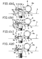
- the spindle 13 of the main body 7 is fitted into the groove 6 of the receiving member 1 and then the rear end section of the main body 7 is pressed downward as indicated by arrow P in Fig. 4(b) so that the lower surfaces of the tripping members 9e, 9e of the hook 9 abut the respective inclined upper surfaces 5a, 5a of the abutments 5, 5 to rotate the hook 9 clockwise as indicated by arrow a against the spring force.
- the tripping members 9e, 9e When the main body is pressed down further, the tripping members 9e, 9e are rotated further in the direction as indicated by arrow a as they are guided by the respective inclined surfaces 5a, 5a until they move off the surfaces 5a, 5a and rotated counterclockwise by the spring force so that the tripping surfaces 9f, 9f of the tripping members 9e, 9e and the respective abutting surfaces 5b, 5b of the abutments 5, 5 come into engagement as illustrated in Fig. 4(c) and consequently the toilet seat 14 and the toilet lid 15 are securely fitted to the toilet pan as the main body 7 is flatly placed on the receiving member 1.
- the hook 9 is lifted upward against the spring force as indicated by arrow b in Fig. 4(d) and then rotated counterclockwise to release the engagement of the abutting surfaces 5b, 5b of the abutments 5, 5 and the respective tripping surfaces 9f, 9f the tripping members 9e, 9e so that the toilet seat 14 and the toilet lid 15 can be removed by lifting said main body 7.
- Figs. 5(a) and (b) and Figs. 6(a) and (b) illustrates a second embodiment of the invention. While the main body 7, the hook 9 and the spring 12 of the first embodiment are realized in so many separate members, the main body 7 and the hook 9 are integrally formed in this second embodiment and the base section of said hook 9 is resiliently formed so that the main body 7 is locked by a receiving member due to the resilience of the hook 9.
- said main body 7 is made of an elastic material such as metal and integrally formed with a hinge case 8a of a hinge 8, said main body having a pair of parallel and longitudinal slits 18, 18 at its rear end to form between them a hook 9, which has along its lower base section a lateral groove 19 to form a thin area 20 just above said groove 19 so that the thin area shows a certain degree of flexibility and the hook 9 may be bent upward against the resilience of that area.
- Tripping members 9e, 9e similar to the those of the first embodiment are arranged on the lower surface of said hook 9.
- the axis 0 of relative rotation of receiving member 1 and front base section of the main body 7 is formed by a ridge 21 which is removably engaged with a groove 22.
- this embodiment has a configuration similar that of the first embodiment and its main body 7 is mounted to and dismounted from the receiving member 1 in a manner similar to that of the first embodiment.
- FIG. 8 an embodiment of the fitting device according to claim (3) will be described by referring to Figs. 8, 9 and 11.
- This embodiment has a configuration basically similar to that of the first and second embodiments described above, a major difference being in that the current embodiment is provided with an additional lever 25, on which a hook 9 is tripped for its pivotal movement.
- a pair of threaded fitting rods 2, 2 are projecting downward from a plate-like receiving member 1 and driven into respective fitting holes 4 of the object of fitting 3.
- a abutment 5 is disposed at the center of the rear portion of the receiving member 1, said abutment 5 having an inclined surface 5a, when abutting surface 5b and a groove 6 formed on its front end as illustrated in Fig. 11.
- Main body 7 is configured substantially similar to the main body of the first embodiment and may be stably tightly placed on said receiving member 1, while it is equipped with a hinge 8 and comprises a pair of brackets 7j, 7j symmetrically arranged at the center of the rear portion of the main body 7 with a certain distance provided therebetween.
- a spindle 10 which is realized in the form of a hollow pin that runs through spindle bearing bores 7f, 7f of said brackets 7j, 7j in such a manner that the hook 9 and the lever 25 may be vertically swingable.
- Said hook 9 comprises a first tripping member 9e extending downward from bearing section 9i with an inversely L-shaped cross section and provided with a tripping surface 9f and a second tripping member 9k extending rearward from said bearing section 9f and provided with a horizontal tripping surface 9j.
- Said hook 9 also comprises a spindle bore 9c and a spring containing cavity 9l formed by radially enlarging a part of said spindle bore 9c, a spring 12 being fitted around said spindle 10 and contained in said spring containing cavity 9l with its one end 12a supported by a spring holder 9h formed by notching a portion of said spring containing cavity 9l and its other end extended out of a horizontal groove 9m on a portion of the side wall of said spring containing cavity 9l and supported by another spring holder 9g arranged on said main body 7 in order to downwardly bias said hook 9 (clockwise as illustrated in Fig. 9), said tripping member 9e being removably received by the abutment 5 of the receiving member 1.
- the front side 9g of said tripping member 9e of said hook 9 preferably have a curved surface with an appropriate radius of curvature so that it may smoothly slide on the inclined surfaces 5a of the abutment 5.
- Said spring 12 is locked against coming off by means of a washer-like lock cap 11 which is rigidly fitted into the spring containing cavity 9l.
- the lever 25 swingably fitted to the main body 7 by means of the spindle 10 is provided with a pair of brackets 25b, 25b having respective spindle bores 25a, 25a and symmetrically arranged with a certain distance provided therebetween.
- a horizontal groove 25c extends between said brackets 25b, 25b and faces forward, a tripping section 25e with a horizontal and upwardly facing tripping surface 25d being formed along the lower edge of said horizontal groove 25c so that the second tripping member 9k of said hook 9 is received by said tripping member 25e when said hook 9 is fitted into said groove 25c.
- Said hook 9 is upwardly swingable against the spring force of the spring 12 by means of said lever 25.
- Said groove 25c is so sized that the second tripping member 9k of the hook 9 is vertically swingable without friction when the main body 7 is fitted to the receiving member.
- the lever 25 has a horizontal upper surface 25f and an inwardly curved rear surface 25g so that it has a substantially triangular side view with finger a grip formed by said upper surface 25h and said curved rear surface 25g and extending rear-upward and a rear wall 25i for covering said hook 9 to blind it.
- a spindle 13 is provided at the front area of said main body 7 and extending from the lateral sides 7d, 7d of the main body 7 as illustrated in Fig. 11. Said spindle 13 provides an axis of vertical swinging motion of said main body 7 when said spindle 13 is fitted into the horizontal groove 6 at the front side of said receiving member 1 for removably fitting said main body 7 to the receiving member 1.
- Fig. 10 shows an embodiment of the device according to claim 4 of the present invention.
- a hook actuating section 9n is formed by extending a member that corresponds to the second tripping member 9k of the first and second embodiments of the hook 9.
- main body 7 of this embodiment has a cover section 7k extending rearward from its rear end.
- This cover section 7k shows an inversely U-shaped cross sectional view formed by its horizontal top wall 71 designed to cover the upper and lateral areas of the hook 9 and a pair of lateral walls 7m, 7m projecting downward from the lateral edges of said top wall 71 and having a rear opening.
- the hook 9 can be rotated upward against the spring force of the spring to release the engagement between its tripping member 9e and the abutment of the receiving member 1 by holding said top wall 71 and said hook actuating section 9n rearwardly extended from the bearing section 9i with a thumb and a forefinger.
- a device according to claim (3) or claim (4) can be fitted to a toilet pan in a substantially same manner as a device according to claim (1) or (2) in order to swingably fit a toilet seat and a toilet lid to the pan.
- a device of Figure 1 can be used for removably fitting a toilet seat and a toilet lid to a toilet pan by simply bringing the main body and the receiving member into engagement at their base sections to provide an axis of rotation, pressing down the front end of said main body relative to the receiving member around the axis and then rotating upward the front end of the hook so that the toilet pan, the toilet seat and the toilet lid can be serviced and maintained without difficulty.
- both the toilet and the toilet lid can be easily removed from the toilet pan for cleaning. Since the hinge of the device is free from any screws and protrusions, a toilet pan equipped with such a device can be shipped after assembling it with a toilet seat and a toilet lid with the receiving member fitted to the toilet pan. The toilet seat or the toilet lid of the assembly can replaced without difficulty whenever it is damaged for some reason.
- a device of Figure 5 can be securely fitted to an object of fitting by simply pressing the fitting rod of the receiving member without nuts and hence without requiring any screwing operation.
- a device comprises a hook which is contained within a lever, it offers an esthetically improved appearance because the hook as well as the area of engagement of the tripping member of the hook and the abutment of the receiving member are not visible from outside. Besides, such an arrangement provides an improved safety when the main body is fitted to or removed from the receiving member because it eliminates any risk of pinched fingers during the fitting or removing operation. Moreover, the lever provides easy releasing operations.
- a device according to Fig. 10 is provided with a cover extended from the main body to cover the hook and its axis of rotation as well as the spring, it offers an even more improved appearance and the cover effectively protects the axis of rotation of the hook against dust and dirt.
- the hook can be rotated by holding with hand the hook actuating section projecting from the hook along with the cover of the main body, the hook can be operated with an enhanced easiness.
Landscapes
- Health & Medical Sciences (AREA)
- Public Health (AREA)
- Engineering & Computer Science (AREA)
- Mechanical Engineering (AREA)
- Toilet Supplies (AREA)
Description
- This invention relates to a hinge device, for fitting swingable items such as a toilet seat and a toilet lid to a toilet pan.
- Known devices designed for fitting a toilet seat and a toilet lid to a toilet pan are normally classified into types as described below.
- One is a type to be used with a toilet pan having a projection for receiving a horizontal spindle that swingably support a toilet seat and a toilet lid. Another is a type to be used with a toilet pan having a pair of vertical bores for receiving pins or threaded rods projecting downward from a hinge connecting a toilet seat and a toilet lid.
- However, a device of the former type is accompanied by difficulties in fitting and removing the spindle, making it far from a one-touch system. Moreover, the projection provided on the toilet can become an obstacle in cleaning operations.
- A device of the latter type is also accompanied by difficulties in fitting and removing pins or screwed rods, and hence the toilet seat and the toilet lid. Moreover, since the vertical bores for receiving pins or screwed rods are not through-bores, they are not easily accessible for cleaning and can retain contaminated water. Besides, devices of both the former and the latter types comprises long fitting screws, entailing packaging problems for shipment and transportation.
- WO-A-86/02402 discloses a hinge device comprising a receiving member for fitting to fixed structure a main body for fitting over the receiving member, the front end of said main body forming an axis of rotation when removably fitted to the corresponding front edge of the receiving member and having a hook at its rear end for engaging an abutment which projects from the rear of the receiving member, the abutment having a downwardly-inclined upper surface, the hook being vertically rotatably mounted on a spindle and spring-biassed to a position in which it locks with the abutment of the receiving member, and the main body having a hinge adjacent its front edge and the main body is projecting rearwardly from the hinge.
- In accordance with the present invention, the hinge device is characterised in that the hinge is arranged for pivotally mounting a toilet seat and a toilet lid to a toilet pan, and said spindle also supports an additional manually-operable lever which includes a tripping section arranged, upon manually turning the lever about the spindle, to engage the hook and rotate the latter against its spring bias and unlock the hook from said abutment.
- The receiving member of a device according to the invention can be rigidly fitted to an object, such as a toilet pan, by means of adhesive.
- Through engagement of the front end of said receiving member and that of the main body, there is formed an axis of rotation, around which the main body is rotated as it is pressed down (toward the receiving member) until the hook abuts the abutment of said receiving member. When the main body is pressed further down, said hook becomes rotated against the spring force of the spring and, as the upper surface of the abutment is inclined downwards toward the rear, the hook slides along that surface, until the hook is free to rotate back by the biasing force of the spring so that it engages with the abutment of the receiving member and consequently the main body is locked against movement relative to the receiving member.
- Since said main body is formed with a hinge for swingably mounting the toilet seat and the toilet lid, the toilet seat and the toilet lid are swingably fitted to the toilet pan when the main body is locked to the receiving member.
- For removing the toilet seat and the toilet lid from the toilet pan, the engagement between the hook and the abutment can be released by simply lifting the lever to rotate the hook against the biasing force of the spring. Therefore, the hook, the main body and the hinge can be removed from the receiving member without difficulty.
- Embodiments of this invention will now be described by way of examples only and with reference to the accompanying drawings, in which:
- Fig. 1 is an exploded perspective view of an embodiment of hinge device for fitting a toilet seat and a toilet lid to a toilet pan;
- Fig. 2 is an enlarged sectional side view of the embodiment of Fig. 1, showing a portion thereof when it is locked;
- Fig. 3 is an enlarged sectional side view of the embodiment of Fig. 2, showing a portion thereof when it is unlocked;
- Figs. 4(a), (b), (c) and (d) are sectional side views of the embodiment of Fig. 1, showing in sequence how it is released from a locked condition;
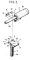
- Fig. 5 is an exploded perspective view of a second embodiment of the invention;
- Figs. 6 (a) and (b) are sectional side views of the embodiment of Fig. 5 under a locked condition;
- Fig. 7 is an exploded perspective view of the embodiment of Fig. 5, showing how it is used to fit a toilet seat and a toilet lid;
- Fig. 8 is an exploded perspective view of an embodiment of the hinge device;
- Fig. 9 is a sectional side view of the embodiment of Fig. 8;
- Fig. 10 is a sectional side view of an embodiment of hinge device;
- Fig. 11 is a partial sectional view of the embodiment of Fig. 10, showing the axis of rotation of its main body around the receiving member arranged at its front end.
- As shown in Figs. 1 through 4, receiving
member 1 of the embodiment is realized in the form of a thick plate made of a synthetic resin material provided with a threadedfitting rod 2 projecting perpendicularly downward from the front area of its lower surface. - Since the illustrated receiving
member 1 is rigidly fitted to an upper edge of a swingable toilet seat by driving thefitting rod 2 into afitting hole 4 bored into the object offitting 3, it can be tightly anchored to the object without loosening because of the firm engagement between thethread 2a formed on the outer periphery of saidfitting rod 2 and the thread formed on the inner periphery of thefitting hole 4. - Alternatively, said receiving
member 1 may be rigidly fitted to the pan by means of adhesive without using afitting rod 2. Said receivingmember 1 is provided with a pair ofabutments - Each of said
abutments upper surface 5a sloping down from its base area toward the tip and a substantiallyhorizontal abutting surface 5b formed on its bottom and extending to the tip. - Said receiving
member 1 is provided on its front side with a horizontal (laterally extending)groove 6 for receiving a spindle that makes the axis of swinging movement of amain body 7 which will be described below. - Said
main body 7 to be removably fitted to said receivingmember 1 has atop wall 7a, arear side wall 7b, afront side wall 7c and a pair oflateral side walls top wall 7a, saidmain body 7 having an inversely U-shaped plan view and being so formed that it can be stably placed on and received by said receiving member. - Said
main body 7 is integrally formed with and projecting rearwardly fromhinge case 8a of ahinge 8. - While the
hinge 8 may be an ordinary but or flap hinge, it is, in this embodiment, a damping hinge comprising ahinge case 8a, though which arotatable shaft 8b is so arranged that it is rotated with a toilet seat and a toilet lid and saidcase 8a contains viscous fluid within the space between saidcase 8a and therotatable shaft 8b so that the viscous shearing resistance of the viscous fluid and the resilient force of a spring (not shown) provide a certain resistive force that appropriately dampen any abrupt movement of the toilet seat and/or toilet lid that may collide against the upper edge of the toilet pan with impact. - A
notch 7e is formed at the rear end of saidmain body 7 along its longitudinal center line to separate itsrear side wall 7b into to parts, in which ahook 9 is arranged and supported by aspindle 10 realized in the form of a hollow pin in such a manner that it can be vertically pivoted around the shaft. -
Said hook 9 has a horizontalupper surface 9a and an inclinedlower surface 9b sloping upward from its front end toward the rear end so that it has a pair of substantially triangular side walls. A horizontal andlateral spindle bore 9c is arranged near the front end of thehook 9 so that it is pivotally supported by saidspindle 10 that runs through saidspindle bore 9c and borne by a pair ofspindle bearing bores 7f bored through thelateral side walls 7d, 7d. Saidspindle 10 is locked against coming off by means of a pair oflock caps 11. - Said
hook 9 has anengaging surface 9d at its front end for abutting the lower side of thetop wall 7a of saidmain body 7 and a pair oftrip members respective tripping surfaces abutting surfaces abutments - The
front sides members hook 9 preferably have a curved surface with an appropriate radius of curvature so that they may smoothly slide on the respectiveinclined surfaces abutments - As illustrated in Fig. 2, said
hook 9 is supported by saidspindle 10 running through thespindle bore 9c and biased counterclockwise by acoil spring 12 having anend 12a received by aspring receiver 9h of thehook 9 and anotherend 12b received by aspring receiver 7g of themain body 7 and saidengaging surface 9d normally abuts thebottom surface 7h of saidmain body 7 so that theupper surface 9a of saidhook 9 is held horizontal against the biasing force of saidspring 12. - Another
spindle 13 realized in the form of a hollow pin is horizontally and laterally arranged at the front area of saidmain body 7 and rigidly received by a pair of spindle bore 7i, 7i bored through thelateral walls main body 7. Saidspindle 13 provides theaxis 0 of vertical swinging movement of themain body 7 as it is received by thegroove 6 of said receivingmember 1 as illustrated in Fig. 4. - For fitting a
toilet seat 14 and atoilet lid 15 to atoilet pan 3 as shown in Fig. 7, thefitting rod 2 is fitted into thefitting hole 3 of thetoilet pan 3 and then the receivingmember 1 is rigidly fitted to its proper position of saidtoilet pan 3 as illustrated in Figs. 4(a) through (d). - Then, the
movable shaft 8b of thehinge 8 is fitted intoshaft bearing holes respective bosses toilet seat 14 and atoilet lid 15 and locked by means of akey 16 arranged on the movable shaft and a key receivinggroove 17 arranged within theshaft bearing holes - Thereafter, both the
toilet seat 14 and thetoilet lid 15 are kept under an rearwardly inclined state as illustrated in Fig. 4(a) by holding by hand thehinge 8 and themain body 7. Thereafter, thespindle 13 of themain body 7 is fitted into thegroove 6 of the receivingmember 1 and then the rear end section of themain body 7 is pressed downward as indicated by arrow P in Fig. 4(b) so that the lower surfaces of thetripping members hook 9 abut the respective inclinedupper surfaces abutments hook 9 clockwise as indicated by arrow a against the spring force. - When the main body is pressed down further, the
tripping members inclined surfaces surfaces tripping surfaces tripping members abutting surfaces abutments toilet seat 14 and thetoilet lid 15 are securely fitted to the toilet pan as themain body 7 is flatly placed on the receivingmember 1. - For removing the
toilet seat 14 and thetoilet lid 15 from the toilet pan, thehook 9 is lifted upward against the spring force as indicated by arrow b in Fig. 4(d) and then rotated counterclockwise to release the engagement of theabutting surfaces abutments respective tripping surfaces tripping members toilet seat 14 and thetoilet lid 15 can be removed by lifting saidmain body 7. - Figs. 5(a) and (b) and Figs. 6(a) and (b) illustrates a second embodiment of the invention. While the
main body 7, thehook 9 and thespring 12 of the first embodiment are realized in so many separate members, themain body 7 and thehook 9 are integrally formed in this second embodiment and the base section of saidhook 9 is resiliently formed so that themain body 7 is locked by a receiving member due to the resilience of thehook 9. - More specifically, said
main body 7 is made of an elastic material such as metal and integrally formed with ahinge case 8a of ahinge 8, said main body having a pair of parallel andlongitudinal slits hook 9, which has along its lower base section alateral groove 19 to form athin area 20 just above saidgroove 19 so that the thin area shows a certain degree of flexibility and thehook 9 may be bent upward against the resilience of that area. - Tripping
members hook 9. - The
axis 0 of relative rotation of receivingmember 1 and front base section of themain body 7 is formed by aridge 21 which is removably engaged with agroove 22. - Otherwise, this embodiment has a configuration similar that of the first embodiment and its
main body 7 is mounted to and dismounted from the receivingmember 1 in a manner similar to that of the first embodiment. -
Reference numeral 23 in Figs. 1, 3, 4(a) through (d) and 5(a) and (b) denotes a pair of indents formed on the lateral sides of the receivingmember 1 andreference numeral 24 denotes a pair of matching projections formed on the bottom of themain body 7 which are engaged into saidrespective indents 23 to block any lateral relative movement of the receivingmember 1 and themain body 7 when themain body 7 is fitted to thereceiving member 1. - Now, an embodiment of the fitting device according to claim (3) will be described by referring to Figs. 8, 9 and 11. This embodiment has a configuration basically similar to that of the first and second embodiments described above, a major difference being in that the current embodiment is provided with an
additional lever 25, on which ahook 9 is tripped for its pivotal movement. - More specifically, a pair of threaded
fitting rods member 1 and driven intorespective fitting holes 4 of the object of fitting 3. Aabutment 5 is disposed at the center of the rear portion of the receivingmember 1, saidabutment 5 having aninclined surface 5a, when abuttingsurface 5b and agroove 6 formed on its front end as illustrated in Fig. 11. -
Main body 7 is configured substantially similar to the main body of the first embodiment and may be stably tightly placed on said receivingmember 1, while it is equipped with ahinge 8 and comprises a pair ofbrackets main body 7 with a certain distance provided therebetween. In this embodiment, however, not only ahook 9 but also alever 25 are held by aspindle 10 which is realized in the form of a hollow pin that runs throughspindle bearing bores brackets hook 9 and thelever 25 may be vertically swingable. - Said
hook 9 comprises a first trippingmember 9e extending downward frombearing section 9i with an inversely L-shaped cross section and provided with a trippingsurface 9f and a second trippingmember 9k extending rearward from saidbearing section 9f and provided with a horizontal trippingsurface 9j. - Said
hook 9 also comprises aspindle bore 9c and a spring containing cavity 9l formed by radially enlarging a part of said spindle bore 9c, aspring 12 being fitted around saidspindle 10 and contained in said spring containing cavity 9l with its oneend 12a supported by aspring holder 9h formed by notching a portion of said spring containing cavity 9l and its other end extended out of ahorizontal groove 9m on a portion of the side wall of said spring containing cavity 9l and supported by anotherspring holder 9g arranged on saidmain body 7 in order to downwardly bias said hook 9 (clockwise as illustrated in Fig. 9), said trippingmember 9e being removably received by theabutment 5 of the receivingmember 1. - In this embodiment again, the
front side 9g of said trippingmember 9e of saidhook 9 preferably have a curved surface with an appropriate radius of curvature so that it may smoothly slide on theinclined surfaces 5a of theabutment 5. - Said
spring 12 is locked against coming off by means of a washer-like lock cap 11 which is rigidly fitted into the spring containing cavity 9l. - The
lever 25 swingably fitted to themain body 7 by means of thespindle 10 is provided with a pair ofbrackets horizontal groove 25c extends between saidbrackets section 25e with a horizontal and upwardly facing trippingsurface 25d being formed along the lower edge of saidhorizontal groove 25c so that the second trippingmember 9k of saidhook 9 is received by said trippingmember 25e when saidhook 9 is fitted into said groove 25c. Saidhook 9 is upwardly swingable against the spring force of thespring 12 by means of saidlever 25. - Said
groove 25c is so sized that the second trippingmember 9k of thehook 9 is vertically swingable without friction when themain body 7 is fitted to the receiving member. - The
lever 25 has a horizontalupper surface 25f and an inwardly curvedrear surface 25g so that it has a substantially triangular side view with finger a grip formed by saidupper surface 25h and said curvedrear surface 25g and extending rear-upward and arear wall 25i for covering saidhook 9 to blind it. - A
spindle 13 is provided at the front area of saidmain body 7 and extending from thelateral sides main body 7 as illustrated in Fig. 11. Saidspindle 13 provides an axis of vertical swinging motion of saidmain body 7 when saidspindle 13 is fitted into thehorizontal groove 6 at the front side of said receivingmember 1 for removably fitting saidmain body 7 to the receivingmember 1. - Fig. 10 shows an embodiment of the device according to
claim 4 of the present invention. In this embodiment, ahook actuating section 9n is formed by extending a member that corresponds to the second trippingmember 9k of the first and second embodiments of thehook 9. - On the other hand,
main body 7 of this embodiment has acover section 7k extending rearward from its rear end. Thiscover section 7k shows an inversely U-shaped cross sectional view formed by its horizontaltop wall 71 designed to cover the upper and lateral areas of thehook 9 and a pair oflateral walls top wall 71 and having a rear opening. Thehook 9 can be rotated upward against the spring force of the spring to release the engagement between its trippingmember 9e and the abutment of the receivingmember 1 by holding saidtop wall 71 and saidhook actuating section 9n rearwardly extended from thebearing section 9i with a thumb and a forefinger. - A device according to claim (3) or claim (4) can be fitted to a toilet pan in a substantially same manner as a device according to claim (1) or (2) in order to swingably fit a toilet seat and a toilet lid to the pan.
- As is apparent from the above description, a device of Figure 1 can be used for removably fitting a toilet seat and a toilet lid to a toilet pan by simply bringing the main body and the receiving member into engagement at their base sections to provide an axis of rotation, pressing down the front end of said main body relative to the receiving member around the axis and then rotating upward the front end of the hook so that the toilet pan, the toilet seat and the toilet lid can be serviced and maintained without difficulty.
- With such a device, both the toilet and the toilet lid can be easily removed from the toilet pan for cleaning. Since the hinge of the device is free from any screws and protrusions, a toilet pan equipped with such a device can be shipped after assembling it with a toilet seat and a toilet lid with the receiving member fitted to the toilet pan. The toilet seat or the toilet lid of the assembly can replaced without difficulty whenever it is damaged for some reason.
- A device of Figure 5 can be securely fitted to an object of fitting by simply pressing the fitting rod of the receiving member without nuts and hence without requiring any screwing operation.
- Since a device according to Fig. 8 comprises a hook which is contained within a lever, it offers an esthetically improved appearance because the hook as well as the area of engagement of the tripping member of the hook and the abutment of the receiving member are not visible from outside. Besides, such an arrangement provides an improved safety when the main body is fitted to or removed from the receiving member because it eliminates any risk of pinched fingers during the fitting or removing operation. Moreover, the lever provides easy releasing operations.
- As a device according to Fig. 10 is provided with a cover extended from the main body to cover the hook and its axis of rotation as well as the spring, it offers an even more improved appearance and the cover effectively protects the axis of rotation of the hook against dust and dirt. As the hook can be rotated by holding with hand the hook actuating section projecting from the hook along with the cover of the main body, the hook can be operated with an enhanced easiness.
Claims (1)
- A hinge device comprising a receiving member (1) for removably fitting to a fixed structure (3), a main body (7) for fitting over the receiving member (1), the front end of said main body (7) forming an axis of rotation when removably fitted to the corresponding front edge of the receiving member and having a hook (9) at its rear end for engaging an abutment (5) which projects from the rear of the receiving member (1), the abutment (5) having a downwardly-inclined upper surface (5a), the hook (9) being vertically rotatably mounted on a spindle (10) and spring-biassed to a position in which it locks with the abutment (5), and the main body (7) having a hinge (8) adjacent its front edge and the main body (7) is projecting rearwardly from the hinge (8), characterised in that the hinge (8) is arranged for pivotally mounting a toilet seat and a toilet lid to a toilet pan, and said spindle (10) also supports an additional manually-operable lever (25) which includes a tripping section (25e) arranged, upon manually turning the lever (25) about the spindle (10), to engage the hook (9) and rotate the latter against its spring bias and unlock the hook (9) from said abutment (5).
Applications Claiming Priority (4)
| Application Number | Priority Date | Filing Date | Title |
|---|---|---|---|
| JP9525789U JPH07159Y2 (en) | 1989-08-11 | 1989-08-11 | Device for attaching the toilet seat and toilet lid to the toilet bowl |
| JP95257/89U | 1989-08-11 | ||
| JP42292/90U | 1990-04-20 | ||
| JP4229290U JPH0722160Y2 (en) | 1990-04-20 | 1990-04-20 | Mounting device for opening and closing members mounted on horizontal shafts such as toilet seats and toilet lids |
Publications (2)
| Publication Number | Publication Date |
|---|---|
| EP0412813A1 EP0412813A1 (en) | 1991-02-13 |
| EP0412813B1 true EP0412813B1 (en) | 1993-10-13 |
Family
ID=26381948
Family Applications (1)
| Application Number | Title | Priority Date | Filing Date |
|---|---|---|---|
| EP90308763A Expired - Lifetime EP0412813B1 (en) | 1989-08-11 | 1990-08-09 | Device for fitting a toilet seat and a toilet lid |
Country Status (7)
| Country | Link |
|---|---|
| US (1) | US5175891A (en) |
| EP (1) | EP0412813B1 (en) |
| KR (1) | KR930004961B1 (en) |
| AU (1) | AU629378B2 (en) |
| CA (1) | CA2023085C (en) |
| DE (1) | DE69003903T2 (en) |
| IE (1) | IE62415B1 (en) |
Families Citing this family (26)
| Publication number | Priority date | Publication date | Assignee | Title |
|---|---|---|---|---|
| FR2702360B1 (en) * | 1993-03-09 | 1996-03-01 | Allibert | DEVICE FOR REMOVABLE CONNECTION AND ARTICULATION OF A SEAT AND / OR A COVER ON A WC BASIN THROUGH A LOCKING PLATE. |
| USD385020S (en) * | 1995-06-07 | 1997-10-14 | Rfsu Rehab Ab | Hinge |
| US5933875A (en) * | 1997-04-03 | 1999-08-10 | Bemis Manufacturing Company | Lift-off toilet seat hinge |
| AU735029B2 (en) * | 1997-07-04 | 2001-06-28 | Caroma Industries Limited | An assembly for connecting a toilet seat hinge support to a toilet pan bolt |
| US6070295A (en) * | 1998-09-22 | 2000-06-06 | Bemis Manufacturing Company | Quick release toilet seat hinge with swivel |
| ATE329114T1 (en) * | 2000-09-29 | 2006-06-15 | Vaillant Gmbh | HINGE FOR FASTENING A LID |
| US6381762B1 (en) | 2001-03-15 | 2002-05-07 | Scott A. Moser | Quick release toilet seat hinge assembly |
| USD481924S1 (en) | 2001-03-21 | 2003-11-11 | Bemis Manufacturing Company | Toilet seat hinge |
| US6449783B1 (en) | 2001-06-29 | 2002-09-17 | Scott A. Moser | Energy transferring toilet seat |
| AU2003233931A1 (en) * | 2002-04-23 | 2003-11-10 | Asem Industrieberatung Und Vermittlung Gmbh | Mounting device for lowering a toilet lid with a quick-fit mounting |
| JP2003329029A (en) * | 2002-05-15 | 2003-11-19 | Fujitsu Ltd | Hinge structure and display device |
| US7338247B2 (en) * | 2004-03-16 | 2008-03-04 | Ateca Steven J | Quick release fastener |
| US7281276B2 (en) * | 2004-04-01 | 2007-10-16 | Kohler Co. | Releasable toilet seat assembly |
| US7155748B2 (en) * | 2004-04-01 | 2007-01-02 | Kohler Co. | Releasable toilet seat assembly |
| US7647652B1 (en) | 2004-08-21 | 2010-01-19 | Baker Theodore W | Toilet seat hinge |
| US8631521B1 (en) | 2004-08-21 | 2014-01-21 | Theodore W. Baker | Toilet seat hinge |
| US7389549B2 (en) * | 2004-09-24 | 2008-06-24 | Kohler Co. | Quick release toilet seat hinge assembly |
| US20060113504A1 (en) * | 2004-12-01 | 2006-06-01 | China Cat, Inc. | Quick release hinge assembly |
| DE102005014185B4 (en) * | 2005-02-14 | 2010-04-15 | Hamberger Industriewerke Gmbh | fastening device |
| KR100657193B1 (en) * | 2005-08-17 | 2006-12-14 | 좌승열 | Toilet seat opening |
| US20080178372A1 (en) * | 2007-01-29 | 2008-07-31 | Matalon Sara | Toilet seat holder |
| US8943618B2 (en) * | 2010-07-13 | 2015-02-03 | Centoco Plastics Limited | Toilet seat hinge assembly |
| MX359929B (en) * | 2011-09-15 | 2018-10-16 | Bemis Mfg Co | Toilet seat hinge. |
| GB2511790B (en) * | 2013-03-13 | 2018-03-14 | Croydex Ltd | Toilet seat mounting method and apparatus |
| KR20180115510A (en) * | 2017-04-13 | 2018-10-23 | 주식회사 대우전자 | Refrigerator and hinge device for door of refrigerator |
| US11564538B2 (en) | 2019-10-21 | 2023-01-31 | Bemis Manufacturing Company | Hinge post for toilet seat |
Family Cites Families (15)
| Publication number | Priority date | Publication date | Assignee | Title |
|---|---|---|---|---|
| US2240220A (en) * | 1938-09-09 | 1941-04-29 | B R E Mfg Co | Water closet seat |
| US4173802A (en) * | 1978-03-16 | 1979-11-13 | Wikstrom Karl Erik | Toilet seat |
| US4326307A (en) * | 1978-06-02 | 1982-04-27 | Baillie Kenneth D | Releasable toilet seat clamp |
| US4319365A (en) * | 1980-02-11 | 1982-03-16 | Bemis Manufacturing Company | No tool toilet seat hardware |
| US4438535A (en) * | 1980-09-24 | 1984-03-27 | Candelario Paredes | Seat and cover assembly for a toilet bowl |
| US4426743A (en) * | 1982-08-24 | 1984-01-24 | Sani-Seat, Incorporated | Toilet seat lifting device |
| DE3587560D1 (en) * | 1984-10-19 | 1993-10-07 | Blum Gmbh Julius | Hinge. |
| US4729134A (en) * | 1985-12-06 | 1988-03-08 | Kohler Co. | Toilet covering hinge assembly |
| US4688274A (en) * | 1985-12-06 | 1987-08-25 | Kohler Co. | Toilet covering hinge assembly |
| AT386862B (en) * | 1985-12-10 | 1988-10-25 | Blum Gmbh Julius | HINGE |
| AT383852B (en) * | 1986-04-10 | 1987-09-10 | Blum Gmbh Julius | HINGE |
| EP0269701B2 (en) * | 1986-06-14 | 1994-07-06 | PAUL HETTICH GMBH & CO. | Furniture hinge |
| DE3701720A1 (en) * | 1987-01-22 | 1988-08-04 | Pag Presswerk Ag | Toilet cover |
| FR2627371B1 (en) * | 1988-02-18 | 1991-05-24 | Tissot Sa | WC WC SEAT |
| US4974262A (en) * | 1988-07-11 | 1990-12-04 | Ginsey Industries, Inc. | Hinge for toilet seat and lid |
-
1990
- 1990-08-06 AU AU60172/90A patent/AU629378B2/en not_active Ceased
- 1990-08-09 DE DE90308763T patent/DE69003903T2/en not_active Expired - Fee Related
- 1990-08-09 EP EP90308763A patent/EP0412813B1/en not_active Expired - Lifetime
- 1990-08-10 CA CA002023085A patent/CA2023085C/en not_active Expired - Fee Related
- 1990-08-10 IE IE290190A patent/IE62415B1/en not_active IP Right Cessation
- 1990-08-11 KR KR1019900012380A patent/KR930004961B1/en not_active Expired - Fee Related
- 1990-08-13 US US07/566,040 patent/US5175891A/en not_active Expired - Fee Related
Also Published As
| Publication number | Publication date |
|---|---|
| KR910004154A (en) | 1991-03-28 |
| IE62415B1 (en) | 1995-01-25 |
| AU629378B2 (en) | 1992-10-01 |
| US5175891A (en) | 1993-01-05 |
| KR930004961B1 (en) | 1993-06-11 |
| DE69003903T2 (en) | 1994-02-10 |
| IE902901A1 (en) | 1991-04-10 |
| CA2023085C (en) | 1993-10-12 |
| CA2023085A1 (en) | 1991-02-12 |
| EP0412813A1 (en) | 1991-02-13 |
| DE69003903D1 (en) | 1993-11-18 |
| AU6017290A (en) | 1991-02-14 |
Similar Documents
| Publication | Publication Date | Title |
|---|---|---|
| IE62415B1 (en) | Device for fitting a toilet seat and a toilet lid | |
| US4753367A (en) | Wastebasket and inner liner retainer | |
| CA1313355C (en) | Step-on wastebasket | |
| US5440814A (en) | Knife with side guards | |
| US5862956A (en) | Dispensing system for flowable liquids | |
| US4953740A (en) | Wastebasket having lid hinge and actuating mechanism protector | |
| EP0530419B1 (en) | Container mounting system | |
| EP0808727B1 (en) | A ring binder | |
| US3831224A (en) | Toggle latch with yoke | |
| EP0313267A1 (en) | Wastebasket with inwardly swinging lid | |
| EP0033509A2 (en) | Latch or buckle for latching lid to container | |
| CA1296843C (en) | Toilet seat or cover retaining device | |
| US5655799A (en) | Latch assembly | |
| JP3342620B2 (en) | Trash can | |
| US4141473A (en) | Spout cover assembly | |
| US5901885A (en) | Cap for shaker | |
| US5243729A (en) | Mop frame holder | |
| US6763937B2 (en) | Paintbox comprising exchangeable paint dishes | |
| JP3130486B2 (en) | Cap for brewing container | |
| GB2044836A (en) | Device for holding a container cover open or partly open | |
| JP2589279B2 (en) | Crescent tablets | |
| CA1094511A (en) | Spout cover assembly | |
| JP3197479B2 (en) | Operating device for latch device in drawer | |
| JP3518730B2 (en) | Door opening and closing device | |
| JP2673676B2 (en) | Case lid locking device |
Legal Events
| Date | Code | Title | Description |
|---|---|---|---|
| PUAI | Public reference made under article 153(3) epc to a published international application that has entered the european phase |
Free format text: ORIGINAL CODE: 0009012 |
|
| AK | Designated contracting states |
Kind code of ref document: A1 Designated state(s): DE FR GB IT |
|
| 17P | Request for examination filed |
Effective date: 19910807 |
|
| 17Q | First examination report despatched |
Effective date: 19911009 |
|
| GRAA | (expected) grant |
Free format text: ORIGINAL CODE: 0009210 |
|
| AK | Designated contracting states |
Kind code of ref document: B1 Designated state(s): DE FR GB IT |
|
| REF | Corresponds to: |
Ref document number: 69003903 Country of ref document: DE Date of ref document: 19931118 |
|
| ITF | It: translation for a ep patent filed | ||
| ET | Fr: translation filed | ||
| PLBE | No opposition filed within time limit |
Free format text: ORIGINAL CODE: 0009261 |
|
| STAA | Information on the status of an ep patent application or granted ep patent |
Free format text: STATUS: NO OPPOSITION FILED WITHIN TIME LIMIT |
|
| 26N | No opposition filed | ||
| PGFP | Annual fee paid to national office [announced via postgrant information from national office to epo] |
Ref country code: GB Payment date: 19970731 Year of fee payment: 8 |
|
| PGFP | Annual fee paid to national office [announced via postgrant information from national office to epo] |
Ref country code: FR Payment date: 19970811 Year of fee payment: 8 |
|
| PG25 | Lapsed in a contracting state [announced via postgrant information from national office to epo] |
Ref country code: GB Free format text: LAPSE BECAUSE OF NON-PAYMENT OF DUE FEES Effective date: 19980809 |
|
| GBPC | Gb: european patent ceased through non-payment of renewal fee |
Effective date: 19980809 |
|
| PG25 | Lapsed in a contracting state [announced via postgrant information from national office to epo] |
Ref country code: FR Free format text: LAPSE BECAUSE OF NON-PAYMENT OF DUE FEES Effective date: 19990430 |
|
| REG | Reference to a national code |
Ref country code: FR Ref legal event code: ST |
|
| PGFP | Annual fee paid to national office [announced via postgrant information from national office to epo] |
Ref country code: DE Payment date: 20030822 Year of fee payment: 14 |
|
| PG25 | Lapsed in a contracting state [announced via postgrant information from national office to epo] |
Ref country code: DE Free format text: LAPSE BECAUSE OF NON-PAYMENT OF DUE FEES Effective date: 20050301 |
|
| PG25 | Lapsed in a contracting state [announced via postgrant information from national office to epo] |
Ref country code: IT Free format text: LAPSE BECAUSE OF NON-PAYMENT OF DUE FEES;WARNING: LAPSES OF ITALIAN PATENTS WITH EFFECTIVE DATE BEFORE 2007 MAY HAVE OCCURRED AT ANY TIME BEFORE 2007. THE CORRECT EFFECTIVE DATE MAY BE DIFFERENT FROM THE ONE RECORDED. Effective date: 20050809 |