EP0412552B1 - Combustion chamber for a Diesel engine - Google Patents
Combustion chamber for a Diesel engine Download PDFInfo
- Publication number
- EP0412552B1 EP0412552B1 EP90115335A EP90115335A EP0412552B1 EP 0412552 B1 EP0412552 B1 EP 0412552B1 EP 90115335 A EP90115335 A EP 90115335A EP 90115335 A EP90115335 A EP 90115335A EP 0412552 B1 EP0412552 B1 EP 0412552B1
- Authority
- EP
- European Patent Office
- Prior art keywords
- section
- combustion chamber
- projection
- side wall
- wall surface
- Prior art date
- Legal status (The legal status is an assumption and is not a legal conclusion. Google has not performed a legal analysis and makes no representation as to the accuracy of the status listed.)
- Expired - Lifetime
Links
Images

Classifications
-
- F—MECHANICAL ENGINEERING; LIGHTING; HEATING; WEAPONS; BLASTING
- F02—COMBUSTION ENGINES; HOT-GAS OR COMBUSTION-PRODUCT ENGINE PLANTS
- F02B—INTERNAL-COMBUSTION PISTON ENGINES; COMBUSTION ENGINES IN GENERAL
- F02B23/00—Other engines characterised by special shape or construction of combustion chambers to improve operation
- F02B23/02—Other engines characterised by special shape or construction of combustion chambers to improve operation with compression ignition
- F02B23/06—Other engines characterised by special shape or construction of combustion chambers to improve operation with compression ignition the combustion space being arranged in working piston
- F02B23/0672—Omega-piston bowl, i.e. the combustion space having a central projection pointing towards the cylinder head and the surrounding wall being inclined towards the cylinder center axis
-
- F—MECHANICAL ENGINEERING; LIGHTING; HEATING; WEAPONS; BLASTING
- F02—COMBUSTION ENGINES; HOT-GAS OR COMBUSTION-PRODUCT ENGINE PLANTS
- F02F—CYLINDERS, PISTONS OR CASINGS, FOR COMBUSTION ENGINES; ARRANGEMENTS OF SEALINGS IN COMBUSTION ENGINES
- F02F3/00—Pistons
- F02F3/26—Pistons having combustion chamber in piston head
-
- F—MECHANICAL ENGINEERING; LIGHTING; HEATING; WEAPONS; BLASTING
- F02—COMBUSTION ENGINES; HOT-GAS OR COMBUSTION-PRODUCT ENGINE PLANTS
- F02B—INTERNAL-COMBUSTION PISTON ENGINES; COMBUSTION ENGINES IN GENERAL
- F02B23/00—Other engines characterised by special shape or construction of combustion chambers to improve operation
- F02B23/02—Other engines characterised by special shape or construction of combustion chambers to improve operation with compression ignition
- F02B23/06—Other engines characterised by special shape or construction of combustion chambers to improve operation with compression ignition the combustion space being arranged in working piston
- F02B23/0645—Details related to the fuel injector or the fuel spray
- F02B23/0648—Means or methods to improve the spray dispersion, evaporation or ignition
- F02B23/0651—Means or methods to improve the spray dispersion, evaporation or ignition the fuel spray impinging on reflecting surfaces or being specially guided throughout the combustion space
-
- F—MECHANICAL ENGINEERING; LIGHTING; HEATING; WEAPONS; BLASTING
- F02—COMBUSTION ENGINES; HOT-GAS OR COMBUSTION-PRODUCT ENGINE PLANTS
- F02B—INTERNAL-COMBUSTION PISTON ENGINES; COMBUSTION ENGINES IN GENERAL
- F02B2275/00—Other engines, components or details, not provided for in other groups of this subclass
- F02B2275/14—Direct injection into combustion chamber
-
- F—MECHANICAL ENGINEERING; LIGHTING; HEATING; WEAPONS; BLASTING
- F02—COMBUSTION ENGINES; HOT-GAS OR COMBUSTION-PRODUCT ENGINE PLANTS
- F02B—INTERNAL-COMBUSTION PISTON ENGINES; COMBUSTION ENGINES IN GENERAL
- F02B3/00—Engines characterised by air compression and subsequent fuel addition
- F02B3/06—Engines characterised by air compression and subsequent fuel addition with compression ignition
-
- Y—GENERAL TAGGING OF NEW TECHNOLOGICAL DEVELOPMENTS; GENERAL TAGGING OF CROSS-SECTIONAL TECHNOLOGIES SPANNING OVER SEVERAL SECTIONS OF THE IPC; TECHNICAL SUBJECTS COVERED BY FORMER USPC CROSS-REFERENCE ART COLLECTIONS [XRACs] AND DIGESTS
- Y02—TECHNOLOGIES OR APPLICATIONS FOR MITIGATION OR ADAPTATION AGAINST CLIMATE CHANGE
- Y02T—CLIMATE CHANGE MITIGATION TECHNOLOGIES RELATED TO TRANSPORTATION
- Y02T10/00—Road transport of goods or passengers
- Y02T10/10—Internal combustion engine [ICE] based vehicles
- Y02T10/12—Improving ICE efficiencies
Definitions
- the present invention relates to a combustion chamber with an injection nozzle for a diesel engine, and more particularly to the configuration of a combustion chamber for reducing the creation of noxious components in the exhaust gas comprising the features of the preamble of claim 1.
- combustion chamber of a diesel engine wherein the combustion chamber is provided as a concave section in the head surface of a piston and fuel is injected directly into the air which is compressed in this combustion chamber.
- This type of combustion chamber is referred to as a toroidal combustion chamber.
- FR-A-2 388 997 describes an combustion chamber for a direct injection type of diesel engine and a injection nozzle, the combustion chamber comprising a built-up projection formed in a conical shape at the center of a bottom surface of a circular concave section formed in the head section of a piston, the circular concave section comprising a peripheral edge section , formed as the arc of a circle, which is joined to this projection, and is connected to a side wall surface.
- BE-A-496 710 discloses a combustion chamber wherein the projection comprises two regions with different slope angles.
- EP-A-271 478 discloses a combustion chamber wherein the projection has a convex shape.
- the air inside the combustion chamber is caused to rotate to produce an eddying flow. Then, in order for the flow of fuel to intersect this eddying flow and be accelerated, the eddying flow must have the strength to rotate over the entire periphery so that the fuel is uniformly mixed in the circumferential direction, in the interval between consecutive injections.
- the mixture of fuel and air is made uniform, and, in particular, there is no temporary concentration of fuel. Therefore, because the fuel is injected continuously, there is an effective reduction of black smoke and NO x which are noxious substances in the exhaust gases.
- the shape of the concave section in the combustion chamber be made heart-shaped, or hemispherical or globular.
- the fuel which is injected into the center of the combustion chamber is not sufficiently dispersed and is not broken down into fine particles. It is therefore not in a state in which ignition can occur from contact with the air.
- the air at the center of the eddying flow does not particularly contribute to the effect of smooth ignition of the fuel.
- the mixture of the fuel and air close to the surface of the side wall is vigorously mixed, but there is a tendency toward a lack of air which is necessary for combustion. Therefore, when sufficient air to burn the fuel is lacking, incomplete combustion occurs and there is a large amount of noxious components produced in the exhaust gases.
- Another object of the present invention is to provide a combustion chamber for a diesel engine into which a maximum amount of air can be fed at a position where the fuel can be vigorously mixed with the air.
- a further object of the present invention is to provide a combustion chamber for a diesel engine in which the fuel and air are mixed with improved blending and agitation.
- a combustion chamber for a direct injection type of diesel engine wherein the center of the bottom surface of a circular concave section formed in the head section of a piston has a projection which is built up in a conical shape.
- This projection is made up of a bottom section with a steep slope, positioned at the bottom surface of the concave section, and a conical trapezoid with a gentle slope on the top section positioned at the head surface. Accordingly, because the head is flat, the projection is prevented from interfering with the injection nozzle and the air at the center of the combustion chamber is guided toward the side wall surface.
- the head angle of the conical trapezoid is made 10° to 30° smaller than the cone angle of the injection nozzle, and the angle between the sloped surface of the bottom section which faces the side wall surface of the concave section is set at 0° to 30°. Accordingly, the fuel which is sprayed from the injection nozzle is prevented from impacting the bottom section of the projection, and this fuel flows toward the side wall surface.
- the re-entrant angle of the side wall surface is set at 20° to 30°. Accordingly, when the piston is elevated the flow of the air which enters the combustion chamber is turbulent so that laminar flow at the sidewall surface is prevented and the agitation of the fuel is improved.
- the inner diameter D2 of an open end 2a of a circular depression is smaller than the maximum inner diameter D3 of the inside of the combustion chamber (D2 ⁇ D3).
- a projection 3 is formed at the center of the bottom surface.
- the projection 3 is larger than a conventional projection, and approximately one-half of the projection bottom (hereinafter referred to as the bottom section) 3a is a cone which rises steeply upright.
- the top half (hereinafter referred to as the top section) 3b, which is joined to the bottom section 3a, is an almost conical trapezoid with a surface which has a more gentle slope than the lower section 3a.
- the depth of a head section level surface, specifically, the section at the center of the combustion chamber 2 is slightly less than that of a conventional projection.
- a head angle ⁇ of the top section of the projection 3, specifically, of the conical trapezoid 3b is a slightly smaller angle than a cone angle ⁇ of an injection nozzle 4 which is mounted above the projection 3 on the centerline of the combustion chamber 2.
- the fuel sprayed from the injection nozzle 4 is prevented from reaching a sloped surface 3c of the bottom section 3a of the projection 3.
- a peripheral edge section and a side wall surface of the bottom section, specifically, a bottom arc section 2b which is joined to the bottom section 3a of the projection 3 of the combustion chamber 2, is formed so that a spherical body can follow along the circumference of the bottom section 3a of the projection 3 when moved with a rolling action, and the outer side section of the bottom surface of the combustion chamber 2 has a cross section which includes a part of a circle, specifically, in the shape of an arc.
- the value D2 is the inside diameter of the open end 2a of the combustion chamber 2, as previously stated.
- a side wall surface 2c joined to the bottom arc section 2b of the combustion chamber 2 is a sloped surface tapering with a decreasing diameter in the upward direction.
- the side wall surface 2c and the sloped surface 3c of the bottom section 3a of the projection 3 are opposedly faced, either in parallel or at a slight angle ⁇ .
- the angle ⁇ is set in a range of 0° to 30°.
- the maximum diameter D3 of the combustion chamber 2 is close to the joint of the side wall surface 2c of the bottom arc section 2b of the combustion chamber 2.
- the re-entrant angle ⁇ ° on the side wall 2c is set in a range of 20° to 25°.
- the inner diameter D2 of the combustion chamber 2 is small, the maximum diameter D3 is large, and the deepest section has a large depth h, so that the projection 3 is large.
- the fuel sprayed from the injection nozzle 4 proceeds toward the bottom section of the side wall surface 2c of the combustion chamber 2 across a rotating flow of air, specifically, an eddying flow, which is created in the combustion chamber 2, and the spray is gradually distributed throughout a flow of new air.
- the center projection 3 is large, the excess air in the vicinity of the side wall surface 2c of the combustion chamber 2 close to the center of the combustion chamber, which does not participate in the combustion, can be effectively utilized at the center of the flow of air to the combustion chamber 2.
- the combustion chamber 2 has a small diameter D2 at an open end 2a, a large maximum diameter D3, and a large maximum depth h, even when the piston 1 is descending, a good eddying flow, specifically, a good airflow, can be maintained.
- FIG. 2 shows another embodiment of the combustion chamber of the present invention.
- the area S i at the approximate center of the combustion chamber 2' is expanded as shown in FIG.
- the combustion chamber 2' with this shape causes the flame to expand toward the center of the combustion chamber 2', further improving combustion after ignition and thus providing reduced fuel costs.
Landscapes
- Engineering & Computer Science (AREA)
- Chemical & Material Sciences (AREA)
- Combustion & Propulsion (AREA)
- Mechanical Engineering (AREA)
- General Engineering & Computer Science (AREA)
- Dispersion Chemistry (AREA)
- Combustion Methods Of Internal-Combustion Engines (AREA)
Description
- The present invention relates to a combustion chamber with an injection nozzle for a diesel engine, and more particularly to the configuration of a combustion chamber for reducing the creation of noxious components in the exhaust gas comprising the features of the preamble of
claim 1. - Conventionally, the structure is known for a combustion chamber of a diesel engine wherein the combustion chamber is provided as a concave section in the head surface of a piston and fuel is injected directly into the air which is compressed in this combustion chamber. This type of combustion chamber is referred to as a toroidal combustion chamber.
- FR-A-2 388 997 describes an combustion chamber for a direct injection type of diesel engine and a injection nozzle, the combustion chamber comprising a built-up projection formed in a conical shape at the center of a bottom surface of a circular concave section formed in the head section of a piston, the circular concave section comprising a peripheral edge section , formed as the arc of a circle, which is joined to this projection, and is connected to a side wall surface.
- BE-A-496 710 discloses a combustion chamber wherein the projection comprises two regions with different slope angles.
- EP-A-271 478 discloses a combustion chamber wherein the projection has a convex shape.
- When the piston rises, the air inside the combustion chamber is caused to rotate to produce an eddying flow. Then, in order for the flow of fuel to intersect this eddying flow and be accelerated, the eddying flow must have the strength to rotate over the entire periphery so that the fuel is uniformly mixed in the circumferential direction, in the interval between consecutive injections.
- In addition, the mixture of fuel and air is made uniform, and, in particular, there is no temporary concentration of fuel. Therefore, because the fuel is injected continuously, there is an effective reduction of black smoke and NOx which are noxious substances in the exhaust gases.
- For these reasons, conventionally, it has been proposed that the shape of the concave section in the combustion chamber be made heart-shaped, or hemispherical or globular.
- However, with a combustion chamber of any of the abovementioned shapes, the combustion at the side wall surface, where the best mixing of the fuel and air is considered to occur, is not complete, and there is a tendency for incomplete combustion to be obtained.
- Specifically, the fuel which is injected into the center of the combustion chamber is not sufficiently dispersed and is not broken down into fine particles. It is therefore not in a state in which ignition can occur from contact with the air. As a result, the air at the center of the eddying flow does not particularly contribute to the effect of smooth ignition of the fuel. The mixture of the fuel and air close to the surface of the side wall is vigorously mixed, but there is a tendency toward a lack of air which is necessary for combustion. Therefore, when sufficient air to burn the fuel is lacking, incomplete combustion occurs and there is a large amount of noxious components produced in the exhaust gases.
- In addition, because the mixing and agitation of the air and fuel at the concave section of the side wall surface depends on the strength of the eddying flow, it is difficult to guarantee a uniform mixing performance.
- It is therefore an object of the present invention to provide, with due consideration to the drawbacks of such conventional combustion chambers, a combustion chamber for a diesel engine which can reduce the occurrence of noxious components, and, in particular, reduce the occurrence of black smoke and NOx in the exhaust gases.
- Another object of the present invention is to provide a combustion chamber for a diesel engine into which a maximum amount of air can be fed at a position where the fuel can be vigorously mixed with the air.
- A further object of the present invention is to provide a combustion chamber for a diesel engine in which the fuel and air are mixed with improved blending and agitation.
- These objects are achieved in the present invention by the provision of a combustion chamber for a direct injection type of diesel engine, wherein the center of the bottom surface of a circular concave section formed in the head section of a piston has a projection which is built up in a conical shape. This projection is made up of a bottom section with a steep slope, positioned at the bottom surface of the concave section, and a conical trapezoid with a gentle slope on the top section positioned at the head surface. Accordingly, because the head is flat, the projection is prevented from interfering with the injection nozzle and the air at the center of the combustion chamber is guided toward the side wall surface.
- In addition, the head angle of the conical trapezoid is made 10° to 30° smaller than the cone angle of the injection nozzle, and the angle between the sloped surface of the bottom section which faces the side wall surface of the concave section is set at 0° to 30°. Accordingly, the fuel which is sprayed from the injection nozzle is prevented from impacting the bottom section of the projection, and this fuel flows toward the side wall surface.
- Further, in the fuel chamber for a diesel engine of the present invention, the re-entrant angle of the side wall surface is set at 20° to 30°. Accordingly, when the piston is elevated the flow of the air which enters the combustion chamber is turbulent so that laminar flow at the sidewall surface is prevented and the agitation of the fuel is improved.
- These and other objects, features, and advantages of the present invention will become more apparent from the following description of the preferred embodiments taken in conjunction with the accompanying drawings, in which:
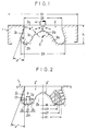
- FIG. 1 is a cross-sectional view of one embodiment of a combustion chamber for a diesel engine according to the present invention.
- FIG. 2 is a cross-sectional view of another embodiment of a combustion chamber for a diesel engine according to the present invention.
- FIG. 3 is a graph which illustrates the relationship between the diameter and the surface area of the combustion chamber shown in FIG. 2.
- Now referring to FIG. 1, in a
combustion chamber 2 formed at the center of the head-section of apiston 1, the inner diameter D₂ of anopen end 2a of a circular depression is smaller than the maximum inner diameter D₃ of the inside of the combustion chamber (D₂ < D₃). Aprojection 3 is formed at the center of the bottom surface. - The
projection 3 is larger than a conventional projection, and approximately one-half of the projection bottom (hereinafter referred to as the bottom section) 3a is a cone which rises steeply upright. The top half (hereinafter referred to as the top section) 3b, which is joined to thebottom section 3a, is an almost conical trapezoid with a surface which has a more gentle slope than thelower section 3a. The depth of a head section level surface, specifically, the section at the center of thecombustion chamber 2 is slightly less than that of a conventional projection. - A head angle β of the top section of the
projection 3, specifically, of theconical trapezoid 3b is a slightly smaller angle than a cone angle ϑ of an injection nozzle 4 which is mounted above theprojection 3 on the centerline of thecombustion chamber 2. Specifically, the head angle β is set at an angle 10° to 30° smaller than the cone angle

top section 3b of theprojection 3 as a conical trapezoid and the head section as a flat surface, obstruction of the injection nozzle 4 is avoided. In addition, by forming thebottom section 3a of theprojection 3 as a steeply upright sloping surface and thetop section 3b as a gently sloping surface, the fuel sprayed from the injection nozzle 4 is prevented from reaching a sloped surface 3c of thebottom section 3a of theprojection 3. - A peripheral edge section and a side wall surface of the bottom section, specifically, a
bottom arc section 2b which is joined to thebottom section 3a of theprojection 3 of thecombustion chamber 2, is formed so that a spherical body can follow along the circumference of thebottom section 3a of theprojection 3 when moved with a rolling action, and the outer side section of the bottom surface of thecombustion chamber 2 has a cross section which includes a part of a circle, specifically, in the shape of an arc. The radius R of this arc is set in the range of R = 0.12 D₂ to 0.18 D₂. Here the value D₂ is the inside diameter of theopen end 2a of thecombustion chamber 2, as previously stated. - A
side wall surface 2c joined to thebottom arc section 2b of thecombustion chamber 2 is a sloped surface tapering with a decreasing diameter in the upward direction. Theside wall surface 2c and the sloped surface 3c of thebottom section 3a of theprojection 3 are opposedly faced, either in parallel or at a slight angle α. The angle α is set in a range of 0° to 30°. The maximum diameter D₃ of thecombustion chamber 2 is close to the joint of theside wall surface 2c of thebottom arc section 2b of thecombustion chamber 2. The re-entrant angle γ° on theside wall 2c is set in a range of 20° to 25°. - In this configuration, the inner diameter D₂ of the
combustion chamber 2 is small, the maximum diameter D₃ is large, and the deepest section has a large depth h, so that theprojection 3 is large. - In the
combustion chamber 2 of the shape shown in FIG. 1, the fuel sprayed from the injection nozzle 4 proceeds toward the bottom section of theside wall surface 2c of thecombustion chamber 2 across a rotating flow of air, specifically, an eddying flow, which is created in thecombustion chamber 2, and the spray is gradually distributed throughout a flow of new air. In addition, because thecenter projection 3 is large, the excess air in the vicinity of theside wall surface 2c of thecombustion chamber 2 close to the center of the combustion chamber, which does not participate in the combustion, can be effectively utilized at the center of the flow of air to thecombustion chamber 2. Furthermore, because thecombustion chamber 2 has a small diameter D₂ at anopen end 2a, a large maximum diameter D₃, and a large maximum depth h, even when thepiston 1 is descending, a good eddying flow, specifically, a good airflow, can be maintained. - As a result, the atomization of the fuel is accelerated, ignition is improved, and the combustion of the fuel in the
combustion chamber 2 is good so that the creation of black smoke is restrained. This results in an improvement in engine performance. - FIG. 2 shows another embodiment of the combustion chamber of the present invention. Now referring to FIG. 2, a combustion chamber 2', in addition to the configuration of the
combustion chamber 2 shown in FIG. 1 has an outercurved surface 2'd with a radius R₁ connected to a side wall surface 2'c of a bottom arc section 2'b, an inner curved surface 2'e with a radius R₂ connected to a bottom section 3'a of a projection 3' (where R₁ ≠ R₂), and has an area (combustion area)
curved surfaces 2'd, 2'e respectively, are separated only by a distance a (where a = approximately 2 to 6 mm), and a flat section 2'f is provided at the bottom surface of the combustion chamber 2', specifically, the bottom arc section 2'b. - The combustion chamber 2' with this shape causes the flame to expand toward the center of the combustion chamber 2', further improving combustion after ignition and thus providing reduced fuel costs.
Claims (5)
- A combustion chamber (2) with an injection nozzle (4) for a direct injection type of diesel engine, the combustion chamber comprising a built-up projection (3) formed in a conical shape at the center of a bottom surface of a circular concave section, formed in the head section of a piston, and a bottom arc section (2b) comprising an arc of a circle, which is joined to this projection (3), and is connected to a side wall surface (2c) characterized in that the projection (3) combines a bottom section (3a) positioned on a bottom surface side formed as a surface (3c) with a steep slope, and a top section (3b) positioned on a head section side formed as a conical trapezoid which has a gently sloping surface; the head angle (β) of the conical trapezoid is formed 10° to 30° smaller than the cone angle (Θ) of the injection nozzle (4); and the angle (α) between the side wall surface of the combustion chamber (2) and the sloped surface of the bottom section which faces the side wall surface is set at 0° to 30°.
- The combustion chamber as claimed in claim 1, wherein the bottom arc section (2b) of the concave section, which connects the bottom section (3a) of the projection (3) and the side wall surface (2c), is formed in a shape which allows a spherical body to be rolled in the circumferential direction; and the radius R of the bottom arc section (2b) is equal to 0.12 D to 0.18 D (R = 0.12 D to 0.18 D), where D is the inner diameter of the open end (2a) of the combustion chamber (2).
- The combustion chamber as claimed in claim 1, wherein the side wall surface (2c) has a re-entrant angle of 20° to 25°.
- The combustion chamber as claimed in claims 1 to 3, wherein the height of the projection (3) is such that the projection (3) extends to a position at which it does not obstruct the spray of fuel from the injection nozzle (4).
- The combustion chamber as claimed in claim 1, wherein the bottom arc section (2b) of the concave section which connects the bottom section (3'a) of the projection (3') and the side wall surface (2c) has a curved surface (2'd) with a radius of R₁ on the outer side which is connected to the side wall, and has a curved surface (2'e) with a radius of R₂ on the inner side which is connected to the bottom section; and a flat section (2'f) is provided between the curved surface (2'd) on the outer side and the curved surface (2'e) on the inner side, with the centers of the radii R₁, R₂ being separated only by a distance a.
Applications Claiming Priority (4)
| Application Number | Priority Date | Filing Date | Title |
|---|---|---|---|
| JP92912/89 | 1989-08-09 | ||
| JP1989092912U JP2571792Y2 (en) | 1989-08-09 | 1989-08-09 | Combustion chamber shape of direct injection diesel engine |
| JP1989112009U JP2602529Y2 (en) | 1989-09-25 | 1989-09-25 | Diesel engine combustion chamber structure |
| JP112009/89 | 1989-09-25 |
Publications (2)
| Publication Number | Publication Date |
|---|---|
| EP0412552A1 EP0412552A1 (en) | 1991-02-13 |
| EP0412552B1 true EP0412552B1 (en) | 1994-04-06 |
Family
ID=26434285
Family Applications (1)
| Application Number | Title | Priority Date | Filing Date |
|---|---|---|---|
| EP90115335A Expired - Lifetime EP0412552B1 (en) | 1989-08-09 | 1990-08-09 | Combustion chamber for a Diesel engine |
Country Status (4)
| Country | Link |
|---|---|
| US (1) | US5099809A (en) |
| EP (1) | EP0412552B1 (en) |
| KR (1) | KR940006054B1 (en) |
| DE (2) | DE412552T1 (en) |
Cited By (1)
| Publication number | Priority date | Publication date | Assignee | Title |
|---|---|---|---|---|
| WO2018017028A1 (en) | 2016-07-19 | 2018-01-25 | Ggi Enerji Sanayi Ve Ticaret A. S. | Combustion chamber for internal combustion engine for use in ci and si engines |
Families Citing this family (33)
| Publication number | Priority date | Publication date | Assignee | Title |
|---|---|---|---|---|
| DE4228518A1 (en) * | 1992-08-27 | 1994-03-03 | Man Nutzfahrzeuge Ag | Combustion chamber shape for air-compressing, self-igniting internal combustion engines |
| DE4228517A1 (en) * | 1992-08-27 | 1994-03-03 | Man Nutzfahrzeuge Ag | Diesel engine |
| US5337714A (en) * | 1993-09-03 | 1994-08-16 | Deere & Company | Engine piston with a dual combustion bowl lip radius |
| JPH07150944A (en) * | 1993-12-02 | 1995-06-13 | Toyota Motor Corp | Combustion chamber structure of direct injection diesel engine |
| JPH0845754A (en) * | 1994-07-26 | 1996-02-16 | Aisan Ind Co Ltd | Ignition coil for internal combustion engine |
| EP0810365A1 (en) * | 1996-05-10 | 1997-12-03 | Steyr-Daimler-Puch Aktiengesellschaft | Diesel combustion engine with direct injection and combustion chamber in the piston |
| DE19621635B4 (en) * | 1996-05-30 | 2004-02-05 | Audi Ag | Diesel engine |
| JP3751462B2 (en) * | 1998-03-27 | 2006-03-01 | 株式会社豊田中央研究所 | Direct injection diesel engine |
| DE19935954A1 (en) * | 1999-07-30 | 2001-02-01 | Opel Adam Ag | Direct-injection air-compressing reciprocating internal combustion engine |
| JP4385547B2 (en) * | 2001-06-06 | 2009-12-16 | マツダ株式会社 | diesel engine |
| KR100428149B1 (en) * | 2001-09-29 | 2004-04-28 | 현대자동차주식회사 | Combustion chamber structure in diesel engine |
| DE10150721B4 (en) * | 2001-10-13 | 2012-02-09 | Daimler Ag | Diesel engine |
| US6832594B2 (en) * | 2002-01-09 | 2004-12-21 | Nissan Motor Co., Ltd. | Direct fuel injection engine |
| US6732703B2 (en) * | 2002-06-11 | 2004-05-11 | Cummins Inc. | Internal combustion engine producing low emissions |
| US7210448B2 (en) * | 2002-06-11 | 2007-05-01 | Cummins, Inc. | Internal combustion engine producing low emissions |
| US6705273B1 (en) * | 2002-09-30 | 2004-03-16 | International Engine Intellectual Property Company, Llc | Combustion chamber |
| JP4384945B2 (en) * | 2004-07-09 | 2009-12-16 | ヤンマー株式会社 | Combustion chamber shape of direct injection diesel engine |
| US6997158B1 (en) * | 2004-10-07 | 2006-02-14 | International Engine Intellectual Property Company, Llc | Diesel combustion chamber |
| FR2878567B1 (en) * | 2004-11-30 | 2007-02-09 | Renault Sas | DIESEL ENGINE WITH DIRECT INJECTION AND METHOD FOR INJECTING FUEL INTO A COMBUSTION CHAMBER OF SUCH AN ENGINE |
| FR2894614B1 (en) * | 2005-12-08 | 2008-02-29 | Renault Sas | INTERNAL COMBUSTION ENGINE COMPRISING A PISTON COMPRISING A COMPLEX GEOMETRY BOSS |
| DE102005060547A1 (en) * | 2005-12-17 | 2007-06-28 | Mahle International Gmbh | Automotive piston for fuel-injected engine has profiled central combustion cavity with rounded edges |
| FR2925606A1 (en) * | 2007-12-19 | 2009-06-26 | Renault Sas | DISSYMMETRIC COMBUSTION CHAMBER FOR THERMAL ENGINE |
| FR2925602A1 (en) * | 2007-12-19 | 2009-06-26 | Renault Sas | DISSYMMETRIC COMBUSTION CHAMBER FOR THERMAL ENGINE |
| FR2925601A1 (en) * | 2007-12-19 | 2009-06-26 | Renault Sas | COMBUSTION CHAMBER FOR THERMAL ENGINE |
| JP5338268B2 (en) * | 2008-11-18 | 2013-11-13 | マツダ株式会社 | Diesel engine combustion chamber structure |
| WO2012125961A1 (en) | 2011-03-17 | 2012-09-20 | Cummins Intellectual Property, Inc. | Piston for internal combustion engine |
| JP2013217306A (en) * | 2012-04-10 | 2013-10-24 | Isuzu Motors Ltd | Combustion chamber structure for direct injection engine |
| CN106414943B (en) | 2014-05-22 | 2019-10-18 | 日产自动车株式会社 | Combustion chamber structure of diesel engine |
| CN104595007B (en) * | 2015-01-16 | 2017-09-29 | 东风商用车有限公司 | Straight-wall double-swirl combustion chamber of diesel engine |
| DE102017206015B4 (en) * | 2017-04-07 | 2019-05-29 | Continental Automotive Gmbh | Combustion chamber arrangement for an internal combustion engine and use of a combustion chamber arrangement for injecting OME fuel |
| JP6485489B2 (en) * | 2017-05-23 | 2019-03-20 | マツダ株式会社 | ENGINE CONTROL DEVICE AND ENGINE CONTROL METHOD |
| KR102463469B1 (en) * | 2017-10-17 | 2022-11-04 | 현대자동차주식회사 | Diesel Engine having Reentrant Combustion Chamber |
| GB2570725B (en) * | 2018-02-06 | 2020-07-01 | Caterpillar Energy Solutions Gmbh | Piston for an internal combustion engine |
Family Cites Families (7)
| Publication number | Priority date | Publication date | Assignee | Title |
|---|---|---|---|---|
| BE469710A (en) * | ||||
| US1865841A (en) * | 1930-03-06 | 1932-07-05 | Oil Engine Dev Company | Oil engine |
| FR1107330A (en) * | 1953-10-08 | 1955-12-29 | Schweizerische Lokomotiv | Internal combustion engine with injection with combustion chamber located in each piston |
| DE2815717A1 (en) * | 1977-04-29 | 1978-11-02 | List Hans | AIR COMPRESSING, DIRECT INJECTING COMBUSTION ENGINE |
| DE2945490A1 (en) * | 1978-11-16 | 1980-05-22 | List Hans | AIR COMPRESSING, DIRECTLY INJECTING INTERNAL COMBUSTION ENGINE |
| AT398606B (en) * | 1986-12-12 | 1995-01-25 | Avl Verbrennungskraft Messtech | AIR COMPRESSING, VALVE CONTROLLED INTERNAL COMBUSTION ENGINE |
| JPH0299718A (en) * | 1988-10-07 | 1990-04-11 | Mitsubishi Motors Corp | Combustion chamber structure of direct injection diesel engine |
-
1990
- 1990-08-08 US US07/564,158 patent/US5099809A/en not_active Expired - Lifetime
- 1990-08-09 DE DE199090115335T patent/DE412552T1/en active Pending
- 1990-08-09 DE DE69007899T patent/DE69007899T2/en not_active Expired - Fee Related
- 1990-08-09 KR KR1019900012247A patent/KR940006054B1/en not_active Expired - Fee Related
- 1990-08-09 EP EP90115335A patent/EP0412552B1/en not_active Expired - Lifetime
Cited By (1)
| Publication number | Priority date | Publication date | Assignee | Title |
|---|---|---|---|---|
| WO2018017028A1 (en) | 2016-07-19 | 2018-01-25 | Ggi Enerji Sanayi Ve Ticaret A. S. | Combustion chamber for internal combustion engine for use in ci and si engines |
Also Published As
| Publication number | Publication date |
|---|---|
| DE69007899D1 (en) | 1994-05-11 |
| US5099809A (en) | 1992-03-31 |
| KR940006054B1 (en) | 1994-07-02 |
| DE412552T1 (en) | 1991-06-13 |
| EP0412552A1 (en) | 1991-02-13 |
| KR910004925A (en) | 1991-03-29 |
| DE69007899T2 (en) | 1994-08-11 |
Similar Documents
| Publication | Publication Date | Title |
|---|---|---|
| EP0412552B1 (en) | Combustion chamber for a Diesel engine | |
| EP0172253B1 (en) | Combustion chamber structure for diesel engines | |
| JPH11117831A (en) | Fuel injection valve for internal combustion engine | |
| JP3301013B2 (en) | Spark ignition combustion method | |
| EP0099548B1 (en) | Direct injection type internal combustion engine | |
| JP3174634B2 (en) | Gas turbine fuel injection system | |
| JPS61171821A (en) | Diesel engine with swirl chamber | |
| JPS63134813A (en) | Combustion chamber of internal combustion engine | |
| JPH041166B2 (en) | ||
| JP2571792Y2 (en) | Combustion chamber shape of direct injection diesel engine | |
| JP3330336B2 (en) | Spark ignition internal combustion engine | |
| JPS6320831Y2 (en) | ||
| JP2770376B2 (en) | Engine piston | |
| JPH11210468A (en) | Combustion chamber of direct injection diesel engine | |
| JP3185234B2 (en) | Direct injection internal combustion engine | |
| JP2564396Y2 (en) | Combustion chamber of subchamber internal combustion engine | |
| JP3263487B2 (en) | Combustion chamber of subchamber internal combustion engine | |
| JPH09236016A (en) | Combustion chamber of a direct injection diesel engine | |
| JP2576466B2 (en) | Stratified combustion engine | |
| JPH11117748A (en) | Combustion chamber of direct injection diesel engine | |
| JP2594054B2 (en) | Direct injection diesel engine | |
| GB2134181A (en) | Self-igniting internal combustion engine having a dynamically balanced piston cavity | |
| JPS6313386Y2 (en) | ||
| JPH08121172A (en) | Combustion chamber for internal combustion engine | |
| EP0140047A2 (en) | Direct fuel injection type internal combustion engine |
Legal Events
| Date | Code | Title | Description |
|---|---|---|---|
| PUAI | Public reference made under article 153(3) epc to a published international application that has entered the european phase |
Free format text: ORIGINAL CODE: 0009012 |
|
| AK | Designated contracting states |
Kind code of ref document: A1 Designated state(s): DE FR GB |
|
| EL | Fr: translation of claims filed | ||
| RIN1 | Information on inventor provided before grant (corrected) |
Inventor name: MIZOTE, EIJI Inventor name: SUZUKI, TETSUO, /MITSUBISHI APARTMENT 625 Inventor name: YAMAKI, YOSHIHISA, /MITSUBISHI SAKURADAI- Inventor name: KAWATANI, TORU ,/MITSUBISHI-JIKO MIYAZAKIDAI-RYO Inventor name: NAKAGAWA, TOMOMI Inventor name: KOHKETSU, SUSUMU,/MITSUBISHI-JIKO |
|
| DET | De: translation of patent claims | ||
| 17P | Request for examination filed |
Effective date: 19910812 |
|
| 17Q | First examination report despatched |
Effective date: 19920724 |
|
| GRAA | (expected) grant |
Free format text: ORIGINAL CODE: 0009210 |
|
| AK | Designated contracting states |
Kind code of ref document: B1 Designated state(s): DE FR GB |
|
| REF | Corresponds to: |
Ref document number: 69007899 Country of ref document: DE Date of ref document: 19940511 |
|
| ET | Fr: translation filed | ||
| PLBI | Opposition filed |
Free format text: ORIGINAL CODE: 0009260 |
|
| 26 | Opposition filed |
Opponent name: AVL GESELLSCHAFT FUER VERBRENNUNGSKRAFTMASCHINEN U Effective date: 19950102 |
|
| PLBO | Opposition rejected |
Free format text: ORIGINAL CODE: EPIDOS REJO |
|
| PLBN | Opposition rejected |
Free format text: ORIGINAL CODE: 0009273 |
|
| STAA | Information on the status of an ep patent application or granted ep patent |
Free format text: STATUS: OPPOSITION REJECTED |
|
| 27O | Opposition rejected |
Effective date: 19960413 |
|
| REG | Reference to a national code |
Ref country code: GB Ref legal event code: IF02 |
|
| REG | Reference to a national code |
Ref country code: GB Ref legal event code: 732E |
|
| REG | Reference to a national code |
Ref country code: FR Ref legal event code: TP |
|
| REG | Reference to a national code |
Ref country code: FR Ref legal event code: CA |
|
| PGFP | Annual fee paid to national office [announced via postgrant information from national office to epo] |
Ref country code: GB Payment date: 20050803 Year of fee payment: 16 |
|
| PGFP | Annual fee paid to national office [announced via postgrant information from national office to epo] |
Ref country code: DE Payment date: 20050804 Year of fee payment: 16 |
|
| PGFP | Annual fee paid to national office [announced via postgrant information from national office to epo] |
Ref country code: FR Payment date: 20050809 Year of fee payment: 16 |
|
| PG25 | Lapsed in a contracting state [announced via postgrant information from national office to epo] |
Ref country code: DE Free format text: LAPSE BECAUSE OF NON-PAYMENT OF DUE FEES Effective date: 20070301 |
|
| GBPC | Gb: european patent ceased through non-payment of renewal fee |
Effective date: 20060809 |
|
| REG | Reference to a national code |
Ref country code: FR Ref legal event code: ST Effective date: 20070430 |
|
| PG25 | Lapsed in a contracting state [announced via postgrant information from national office to epo] |
Ref country code: GB Free format text: LAPSE BECAUSE OF NON-PAYMENT OF DUE FEES Effective date: 20060809 |
|
| PG25 | Lapsed in a contracting state [announced via postgrant information from national office to epo] |
Ref country code: FR Free format text: LAPSE BECAUSE OF NON-PAYMENT OF DUE FEES Effective date: 20060831 |