EP0410558B1 - Film evaporator - Google Patents
Film evaporator Download PDFInfo
- Publication number
- EP0410558B1 EP0410558B1 EP90303174A EP90303174A EP0410558B1 EP 0410558 B1 EP0410558 B1 EP 0410558B1 EP 90303174 A EP90303174 A EP 90303174A EP 90303174 A EP90303174 A EP 90303174A EP 0410558 B1 EP0410558 B1 EP 0410558B1
- Authority
- EP
- European Patent Office
- Prior art keywords
- vessel
- screw
- shaft
- section
- film evaporator
- Prior art date
- Legal status (The legal status is an assumption and is not a legal conclusion. Google has not performed a legal analysis and makes no representation as to the accuracy of the status listed.)
- Expired - Lifetime
Links
Images

Classifications
-
- B—PERFORMING OPERATIONS; TRANSPORTING
- B01—PHYSICAL OR CHEMICAL PROCESSES OR APPARATUS IN GENERAL
- B01D—SEPARATION
- B01D1/00—Evaporating
- B01D1/22—Evaporating by bringing a thin layer of the liquid into contact with a heated surface
- B01D1/222—In rotating vessels; vessels with movable parts
- B01D1/223—In rotating vessels; vessels with movable parts containing a rotor
- B01D1/225—In rotating vessels; vessels with movable parts containing a rotor with blades or scrapers
Definitions
- This invention relates to a film evaporator which may be used for obtaining highly viscous products by evaporating and removing solvents and other volatile components from viscous liquids such as high-polymer resins formed by polymerisation.
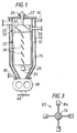
- FIG. 1 of the accompanying drawings A conventional agitated film evaporator is shown schematically in Fig. 1 of the accompanying drawings.
- This evaporator includes a vertical, generally cylindrical jacket 10 surrounding a sealed vessel 12 with a circumferential space 14 formed between them.
- the jacket 10 has nozzles 16 and 18 for a heating fluid to flow through the space 14 and heat the peripheral wall of vessel 12.
- the inside of vessel 12 can be decompressed by connecting its vapor outlet nozzle 20 to a vacuum source via a condenser (not shown) outside the evaporator.
- a vertical shaft 22 extends into the vessel 12 and is journalled by an upper sealed bearing 24 and a lower bearing 26, which is supported by a radial support 28 fixed to the vessel 12.
- the shaft 22 can be rotated by a motor (not shown) situated outside the evaporator.
- a distributor 30 having helical blades 31 and a film forming unit 32 having agitating blades 34 arranged under the distributor.
- the vessel 12 can be supplied through an inlet nozzle 36 with a viscous liquid, which is dispersed by the distributor blades 31 over the inner surface of vessel 12. The descending liquid is then spread as a film on this surface by the agitating blades 34 in order to promote the evaporation of the volatile components.
- the vapor is discharged through the nozzle 20, while the processed liquid is discharged by a gear pump 38 through an outlet 40.
- this type of film evaporator enhances evaporation with the static pressure of liquid being reduced by filming under decompressed condition. This can reduce the evaporation temperature and reduce the thermal influence on the liquid.
- the film is agitated, scraped and moved down by the agitating blades 34 while it is being formed. Consequently, highly viscous liquids can also be processed.
- the collected material may change in quality under the prevailing thermal conditions during collection. If the changed material then becomes detached from the support 28 and mixes with the material being processed, the product quality is lowered. Further, below the film former 32 the highly viscous material descends only slowly under gravity to the pump 38. The material therefore remains within the vessel 12 for a long time, so that the material may deteriorate in quality.
- US-A-3797550 describes a wiped film devolatilizer adapted for processing relatively viscous melts.
- two screw assemblies 176 and 177 are mounted coaxially and counter-rotatably within a housing 174.
- the upper screw 176 includes a lower shaft 180 journalled by and supported on a bearing assembly 182.
- the lower screw 177 comprising an upper stub shaft 187 which is journalled by bearing assembly 195.
- Bearing assemblies 182 and 195 are both supported by radial struts within the housing 174.
- the present invention seeks to provide a film evaporator which does not exhibit these difficulties when used with highly viscous liquids.
- a film evaporator comprising: a sealed vessel adapted to be decompressed and including communicating coaxially disposed upper and lower cylindrical sections, the upper section having a feed inlet adjacent its upper end for material containing volatile components and the lower section having a residue outlet adjacent its lower end; an upper shaft and a lower shaft both extending coaxially within the vessel and journalled by it, the shafts being separately rotatable; film forming means attached to the upper shaft substantially within the upper section and having a plurality of agitating blades which extend radially and are inclined to the horizontal to spread the material as a film on the inner peripheral wall of the vessel and move the material downwardly; heating means provided around the vessel to heat its wall for evaporation of the volatile components; a screw attached coaxially to the lower shaft substantially inside the lower section to move the material downwardly; and bearing means provided between the shafts, characterized in that the bearing means is provided in the screw to support the lower end of the upper shaft.
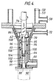
- the evaporator includes a vertically disposed sealed vessel 48 including an upper cylindrical section 50 which is fixed to a frame (not shown).
- the section 50 has a vapor outlet 51 formed adjacent its top and connected to a vacuum source via a condenser (not shown) outside the evaporator in order to decompress the vessel 48.
- the section 50 also has a liquid inlet 52 just below the outlet 51.
- the section 50 is surrounded below the outlet 51 and inlet 52 by a cylindrical jacket 53 with a circumferential space 54 formed between them.
- the jacket 53 has an outlet 56 and an inlet 58 for hot oil as a heating medium to flow through the space 54, so that the inner peripheral surface of section 50 serves as a heating surface for evaporation and keeping warm.
- the lower part of vessel 48 includes an inverted frusto-conical section 62 terminating in a cylindrical section 64, which has a residue outlet 66 adjacent its base. These lower sections 62 and 64 are surrounded by another jacket 68 with a circumferential space 70 between them.
- the jacket 68 similarly has an outlet 72 and an inlet 74 for hot oil.
- An upper shaft 76 extends coaxially with the vessel 48 and is journalled by a shaft closure 78 fixed to the vessel top.
- the shaft 76 can be rotated by a motor (not shown) via a belt 80.
- a distributor 81 having helical blades 82 is fixed coaxially to the shaft 76 at the level of liquid inlet 52. Also fixed to the shaft 76 under the distributor 81 inside the upper section 50 is a film forming unit 83 (Fig. 3) having a number of radial angled agitating blades 84.
- the distributor 81 and film former 83 are substantially the same as those of the prior art evaporator shown in Fig. 1. Inside the frusto-conical section 62, a number of radial angled scraping blades 86 are fixed to the shaft 76.
- a lower shaft 88 extends coaxially with the upper shaft 76 and is journalled by a shaft closure 90 fixed to the base of the vessel. Between the lower shaft 88 and closure 90 is a stuffing box 91 (Fig. 4) to seal the inside of vessel 48.
- the lower shaft 88 is rotated by another motor (not shown) via a belt 92 in the opposite direction to the upper shaft 76.
- the screw 93 has an upper bore 96 and a lower bore 98 which are respectively larger and smaller in diameter.
- the upper bore 96 is provided with a needle bearing 100 at its base.
- the lower shaft 88 has an upper thinner end portion 102 extending coaxially through the lower bore 98 of screw 93 and fixed to it by a bolt 104, so that the screw 93 is located substantially inside the lower cylindrical vessel section 64.
- the upper shaft 76 has a lower thinner end portion 106 extending into the upper bore 96 of screw 93 and supported by the bearing 100. This arrangement eliminates the need for a radial support for the shaft such as that shown in Fig. 1.
- the top end of upper bore 96 is provided with an oil seal 108 to seal the inside of vessel 48, so that the bearing 100 is prevented from contacting the vapor or the viscous material.
- a viscous liquid containing volatile components is fed into the vessel 48 through the inlet 52 and primarily dispersed over the inside of upper vessel section 50 by the distributor blades 82.
- the liquid then descends and is spread as a film onto the inner vessel surface by the agitating blades 84, thus promoting the evaporation of the volatile components and acting to send the liquid downward.
- the vapor is discharged through the outlet 51.
- the processed material descends toward the screw 93, not only by gravity, but also through the assistance of scraping blades 86.
- the highly viscous material is effectively scraped and is fed into the upper portion of screw blade 94.
- the material fed into the screw blade 94 is immediately raked by the screw blade even though it is highly viscous. The material is then forced downwardly by the screw 94, and the residue is extruded through the outlet 66.
- the upper deeper screw groove 95 and wider screw blade 94 enable a larger amount of the material to be taken into the screw blade.
- the lower shallower screw groove can generate sufficient discharge pressure.
- the overall discharge performance of screw 93 is improved.
- the screw blade 94 has the same outer diameter along its entire length so that when the device is disassembled, the screw 93 can be pulled out from the bottom.
- the material is always forced downward by the blades 82, 84, 86 and 94. This enables the residence time of the material within the vessel 48 to be controlled by varying the rotational speeds of shafts 76 and 88.
- the speeds can be individually controlled for attaining the optimum relationship between the outermost peripheral speed of agitating blades 84 and the discharge of screw 93, in order to balance the processing speed at the film former 83 and the discharging speed at the screw 93.
- the viscous liquid is given a swirling motion as it is spread into a film by the agitating blades 84 running at high speed inside the upper vessel section 50.
- the screw blade 94 acts to oppose this swirling flow, and thus no synchronous rotation occurs. This also serves to improve the intake of highly viscous material by the scraping action of screw 94.
Description
- This invention relates to a film evaporator which may be used for obtaining highly viscous products by evaporating and removing solvents and other volatile components from viscous liquids such as high-polymer resins formed by polymerisation.
- A conventional agitated film evaporator is shown schematically in Fig. 1 of the accompanying drawings. This evaporator includes a vertical, generally
cylindrical jacket 10 surrounding a sealedvessel 12 with acircumferential space 14 formed between them. Thejacket 10 hasnozzles space 14 and heat the peripheral wall ofvessel 12. The inside ofvessel 12 can be decompressed by connecting itsvapor outlet nozzle 20 to a vacuum source via a condenser (not shown) outside the evaporator. - A
vertical shaft 22 extends into thevessel 12 and is journalled by an upper sealedbearing 24 and alower bearing 26, which is supported by aradial support 28 fixed to thevessel 12. Theshaft 22 can be rotated by a motor (not shown) situated outside the evaporator. To theshaft 22 are fixed adistributor 30 havinghelical blades 31 and afilm forming unit 32 having agitatingblades 34 arranged under the distributor. - The
vessel 12 can be supplied through aninlet nozzle 36 with a viscous liquid, which is dispersed by thedistributor blades 31 over the inner surface ofvessel 12. The descending liquid is then spread as a film on this surface by theagitating blades 34 in order to promote the evaporation of the volatile components. The vapor is discharged through thenozzle 20, while the processed liquid is discharged by agear pump 38 through anoutlet 40. - Generally, this type of film evaporator enhances evaporation with the static pressure of liquid being reduced by filming under decompressed condition. This can reduce the evaporation temperature and reduce the thermal influence on the liquid. The film is agitated, scraped and moved down by the
agitating blades 34 while it is being formed. Consequently, highly viscous liquids can also be processed. - However, such conventional evaporators have certain disadvantages which are more noticeable when the liquid viscosity is higher. Thus, the processed highly viscous material descending on the inner vessel surface sticks to and collects on the
lower bearing support 28 extending from this surface. If the accumulating material contacts theblades 34, the rotating system may lose its mechanical balance and rotation may be prevented. - Also, the collected material may change in quality under the prevailing thermal conditions during collection. If the changed material then becomes detached from the
support 28 and mixes with the material being processed, the product quality is lowered. Further, below the film former 32 the highly viscous material descends only slowly under gravity to thepump 38. The material therefore remains within thevessel 12 for a long time, so that the material may deteriorate in quality. - US-A-3797550 describes a wiped film devolatilizer adapted for processing relatively viscous melts. In the construction shown in Figure 19 of that document, two screw assemblies 176 and 177 are mounted coaxially and counter-rotatably within a housing 174. The upper screw 176 includes a lower shaft 180 journalled by and supported on a bearing assembly 182. The lower screw 177 comprising an upper stub shaft 187 which is journalled by bearing assembly 195. Bearing assemblies 182 and 195 are both supported by radial struts within the housing 174.
- The present invention seeks to provide a film evaporator which does not exhibit these difficulties when used with highly viscous liquids.
- According to the invention, there is provided a film evaporator comprising:
a sealed vessel adapted to be decompressed and including communicating coaxially disposed upper and lower cylindrical sections, the upper section having a feed inlet adjacent its upper end for material containing volatile components and the lower section having a residue outlet adjacent its lower end;
an upper shaft and a lower shaft both extending coaxially within the vessel and journalled by it, the shafts being separately rotatable;
film forming means attached to the upper shaft substantially within the upper section and having a plurality of agitating blades which extend radially and are inclined to the horizontal to spread the material as a film on the inner peripheral wall of the vessel and move the material downwardly;
heating means provided around the vessel to heat its wall for evaporation of the volatile components;
a screw attached coaxially to the lower shaft substantially inside the lower section to move the material downwardly; and
bearing means provided between the shafts, characterized in that the bearing means is provided in the screw to support the lower end of the upper shaft. - The invention and the working and constructional advantages it exhibits will now be described in greater detail by way of example only with reference to the accompanying drawings, in which:
- Fig. 2 is a perspective view of a film evaporator according to the invention;
- Fig. 3 is an enlarged, radially sectional view of the film forming unit of the evaporator shown in Fig. 2; and
- Fig. 4 is an enlarged side view in axial section of a lower part of the evaporator shown in Fig. 2.
- With reference to Figs. 2 to 4 of the drawings, the evaporator according to the invention includes a vertically disposed sealed
vessel 48 including an uppercylindrical section 50 which is fixed to a frame (not shown). Thesection 50 has avapor outlet 51 formed adjacent its top and connected to a vacuum source via a condenser (not shown) outside the evaporator in order to decompress thevessel 48. Thesection 50 also has aliquid inlet 52 just below theoutlet 51. - The
section 50 is surrounded below theoutlet 51 andinlet 52 by acylindrical jacket 53 with acircumferential space 54 formed between them. Thejacket 53 has anoutlet 56 and aninlet 58 for hot oil as a heating medium to flow through thespace 54, so that the inner peripheral surface ofsection 50 serves as a heating surface for evaporation and keeping warm. - The lower part of
vessel 48 includes an inverted frusto-conical section 62 terminating in acylindrical section 64, which has aresidue outlet 66 adjacent its base. Theselower sections jacket 68 with acircumferential space 70 between them. Thejacket 68 similarly has anoutlet 72 and aninlet 74 for hot oil. - An
upper shaft 76 extends coaxially with thevessel 48 and is journalled by ashaft closure 78 fixed to the vessel top. Theshaft 76 can be rotated by a motor (not shown) via abelt 80. - A
distributor 81 havinghelical blades 82 is fixed coaxially to theshaft 76 at the level ofliquid inlet 52. Also fixed to theshaft 76 under thedistributor 81 inside theupper section 50 is a film forming unit 83 (Fig. 3) having a number of radial angledagitating blades 84. Thedistributor 81 and film former 83 are substantially the same as those of the prior art evaporator shown in Fig. 1. Inside the frusto-conical section 62, a number of radial angledscraping blades 86 are fixed to theshaft 76. - A
lower shaft 88 extends coaxially with theupper shaft 76 and is journalled by ashaft closure 90 fixed to the base of the vessel. Between thelower shaft 88 andclosure 90 is a stuffing box 91 (Fig. 4) to seal the inside ofvessel 48. Thelower shaft 88 is rotated by another motor (not shown) via abelt 92 in the opposite direction to theupper shaft 76. - A
screw 93 having ahelical blade 94 of opposite hand to theblades spiral groove 95 which is deeper at its upper end, is attached toshaft 88. As shown in Fig. 4, thescrew 93 has anupper bore 96 and alower bore 98 which are respectively larger and smaller in diameter. Theupper bore 96 is provided with a needle bearing 100 at its base. - The
lower shaft 88 has an upperthinner end portion 102 extending coaxially through thelower bore 98 ofscrew 93 and fixed to it by abolt 104, so that thescrew 93 is located substantially inside the lowercylindrical vessel section 64. - The
upper shaft 76 has a lowerthinner end portion 106 extending into theupper bore 96 ofscrew 93 and supported by thebearing 100. This arrangement eliminates the need for a radial support for the shaft such as that shown in Fig. 1. The top end ofupper bore 96 is provided with anoil seal 108 to seal the inside ofvessel 48, so that thebearing 100 is prevented from contacting the vapor or the viscous material. - In operation, a viscous liquid containing volatile components is fed into the
vessel 48 through theinlet 52 and primarily dispersed over the inside ofupper vessel section 50 by thedistributor blades 82. The liquid then descends and is spread as a film onto the inner vessel surface by theagitating blades 84, thus promoting the evaporation of the volatile components and acting to send the liquid downward. The vapor is discharged through theoutlet 51. - The processed material descends toward the
screw 93, not only by gravity, but also through the assistance ofscraping blades 86. The highly viscous material is effectively scraped and is fed into the upper portion ofscrew blade 94. - The material fed into the
screw blade 94 is immediately raked by the screw blade even though it is highly viscous. The material is then forced downwardly by thescrew 94, and the residue is extruded through theoutlet 66. - The upper
deeper screw groove 95 andwider screw blade 94 enable a larger amount of the material to be taken into the screw blade. The lower shallower screw groove can generate sufficient discharge pressure. Thus, the overall discharge performance ofscrew 93 is improved. - The
screw blade 94 has the same outer diameter along its entire length so that when the device is disassembled, thescrew 93 can be pulled out from the bottom. - The material is always forced downward by the
blades vessel 48 to be controlled by varying the rotational speeds ofshafts blades 84 and the discharge ofscrew 93, in order to balance the processing speed at the film former 83 and the discharging speed at thescrew 93. - The viscous liquid is given a swirling motion as it is spread into a film by the agitating
blades 84 running at high speed inside theupper vessel section 50. Thescrew blade 94 acts to oppose this swirling flow, and thus no synchronous rotation occurs. This also serves to improve the intake of highly viscous material by the scraping action ofscrew 94.
Claims (5)
- A film evaporator comprising:
a sealed vessel (48) adapted to be decompressed and including communicating coaxially disposed upper and lower cylindrical sections, the upper section (50) having a feed inlet (52) adjacent its upper end for material containing volatile components and the lower section (64) having a residue outlet (66) adjacent its lower end;
an upper shaft (76) and a lower shaft (88) both extending coaxially within the vessel and journalled by it, the shafts being separately rotatable;
film forming means (83) attached to the upper shaft substantially within the upper section and having a plurality of agitating blades (84) which extend radially and are inclined to the horizontal to spread the material as a film on the inner peripheral wall of the vessel and move the material downwardly;
heating means (53,54) provided around the vessel to heat its wall for evaporation of the volatile components;
a screw (93) attached coaxially to the lower shaft substantially inside the lower section to move the material downwardly; and
bearing means (100) provided between the shafts, characterized in that the bearing means (100) is provided in the screw (93) to support the lower end of the upper shaft (76). - A film evaporator according to claim 1, wherein the bearing means (100) is a needle bearing.
- A film evaporator according to claim 1 or claim 2, wherein the screw (93) forms a spiral groove (95) which is deeper adjacent the upper end of the screw.
- A film evaporator according to any one of claims 1 to 3, wherein the screw (93) has a helical blade (94) of the opposite hand to that of the agitating blades (84) and wherein the shafts are adapted to be rotated in opposite directions.
- A film evaporator according to any one of claims 1 to 4, wherein the vessel further includes an inverted frusto-conical section (62) intermediate the upper and lower cylindrical sections (50 and 64) and a plurality of scraping blades (86) extending radially from the upper, shaft (76) within the frusto-conical section, the scraping blades being inclined to the horizontal so as to move the material downwardly.
Applications Claiming Priority (2)
| Application Number | Priority Date | Filing Date | Title |
|---|---|---|---|
| JP194529/89 | 1989-07-26 | ||
| JP1194529A JPH0698242B2 (en) | 1989-07-26 | 1989-07-26 | Thin-film evaporator screw-blade discharge device |
Publications (3)
| Publication Number | Publication Date |
|---|---|
| EP0410558A2 EP0410558A2 (en) | 1991-01-30 |
| EP0410558A3 EP0410558A3 (en) | 1991-05-22 |
| EP0410558B1 true EP0410558B1 (en) | 1995-05-24 |
Family
ID=16326053
Family Applications (1)
| Application Number | Title | Priority Date | Filing Date |
|---|---|---|---|
| EP90303174A Expired - Lifetime EP0410558B1 (en) | 1989-07-26 | 1990-03-23 | Film evaporator |
Country Status (4)
| Country | Link |
|---|---|
| US (1) | US5185060A (en) |
| EP (1) | EP0410558B1 (en) |
| JP (1) | JPH0698242B2 (en) |
| DE (1) | DE69019623T2 (en) |
Families Citing this family (22)
| Publication number | Priority date | Publication date | Assignee | Title |
|---|---|---|---|---|
| TW279808B (en) * | 1992-10-29 | 1996-07-01 | Idemitsu Kosan Co | |
| US5573635A (en) * | 1993-03-15 | 1996-11-12 | Buss Ag | Thin film evaporating device |
| DE19600630A1 (en) * | 1996-01-10 | 1997-07-17 | Bayer Ag | Process and device for the continuous evaporation of viscous, sticky solutions and suspensions to dry matter |
| FR2749769B1 (en) * | 1996-06-18 | 1998-08-28 | Quiot Alain | SOLVENT EVAPORATION APPARATUS |
| GB2347874B (en) * | 1999-03-19 | 2002-10-16 | Bch Ltd | An evaporator |
| DE10038986C2 (en) * | 2000-08-10 | 2002-07-11 | Hans Georg Genser | Sealing device for sealing a cavity rotatable about an axis of rotation |
| DE10050997C1 (en) * | 2000-10-14 | 2001-12-06 | Aventis Cropscience Gmbh | Thin layer vaporizer used for concentration viscous, temperature-sensitive and/or coating-forming materials has a bearing pin and a bearing bushing having the same surface hardness |
| CN100391569C (en) * | 2005-11-29 | 2008-06-04 | 广东华润涂料有限公司 | Diaphragm treatment equipment for removing free monomer of additive compound of polyurethane |
| DE102007045156A1 (en) * | 2007-09-20 | 2009-04-02 | Evonik Röhm Gmbh | Degassing extruder for degassing a polymer material and method for degassing a syrup from polymers, solvents and / or monomers using a degassing extruder |
| JP5222183B2 (en) * | 2009-03-03 | 2013-06-26 | 正夫 金井 | Continuous dryer |
| IES20110203A2 (en) * | 2010-04-23 | 2011-11-23 | Regenerative Sciences Patents Ltd | Method and system for hydrocarbon extraction |
| US8997554B2 (en) * | 2012-04-20 | 2015-04-07 | Halliburton Energy Services, Inc. | Method and apparatus for solid-liquid separation of drilling fluids for analysis |
| US20170080354A1 (en) * | 2015-01-20 | 2017-03-23 | Artisan Industries Inc. | Thin-Film Evaporator with Screw Outfeed |
| ES2914179T3 (en) * | 2016-11-08 | 2022-06-07 | Buss Sms Canzler Gmbh | Thin layer treatment device |
| IT201900005192A1 (en) * | 2019-04-05 | 2020-10-05 | Vb Soluzioni E Tecnologie S R L | EXTRUSION PLANT FOR POLYMERIC MATERIAL PROCESSING |
| FI20195926A1 (en) * | 2019-06-12 | 2020-12-13 | Aurotec Gmbh | Thin-film treatment apparatus |
| CH716490A1 (en) * | 2019-08-12 | 2021-02-15 | Buss Sms Canzler Gmbh | Device for the thermal treatment of material, in particular for the thermal separation of material components contained in the material. |
| CN110665243A (en) * | 2019-11-14 | 2020-01-10 | 杭州富春食品添加剂有限公司 | Evaporator for producing high-purity low-glycerol molecular distillation monoglyceride |
| CN110947197B (en) * | 2019-12-26 | 2021-12-03 | 数谱科技(浙江)有限公司 | Distributing device for thin film evaporator |
| CN111346394A (en) * | 2020-04-29 | 2020-06-30 | 吉林中粮生化有限公司 | Polylactic acid devolatilization evaporator |
| CN111773752B (en) * | 2020-06-11 | 2021-11-26 | 广东轻工职业技术学院 | Resource utilization device and method for kumquat pulp |
| IT202100012026A1 (en) * | 2021-05-11 | 2022-11-11 | Vb Soluzioni E Tecnologie S R L | CENTRIFUGATION STATION FOR EXTRUSION PLANTS |
Family Cites Families (13)
| Publication number | Priority date | Publication date | Assignee | Title |
|---|---|---|---|---|
| DE277883C (en) * | 1913-05-09 | 1914-09-14 | ||
| US2774415A (en) * | 1951-10-25 | 1956-12-18 | Rodney Hunt Machine Co | Evaporator |
| US3334680A (en) * | 1965-06-07 | 1967-08-08 | Head Wrightson & Co Ltd | Rotary wiped film evaporator |
| US3428106A (en) * | 1965-10-27 | 1969-02-18 | Balfour & Co Ltd Henry | Film molecular stills and evaporators |
| US3357478A (en) * | 1966-12-05 | 1967-12-12 | Artisan Ind | Thin film processing apparatus |
| US3357477A (en) * | 1966-12-23 | 1967-12-12 | Artisan Ind | Thin film processing apparatus |
| CH453297A (en) * | 1967-03-21 | 1968-06-14 | Bayer Ag | Rotor for thin film evaporator |
| CH515063A (en) * | 1969-04-15 | 1971-11-15 | Luwa Ag | Thin film apparatus |
| US3630045A (en) * | 1970-04-24 | 1971-12-28 | Howard L Lunde | Machines for producing ice |
| US3797550A (en) * | 1971-08-16 | 1974-03-19 | Monsanto Co | Wiped film devolatilizer construction |
| CS229404B1 (en) * | 1981-06-22 | 1984-06-18 | Alexander Prof Drsc Tkac | Bloc short travel evaporator with a wiped film |
| DE3418982A1 (en) * | 1984-05-22 | 1985-11-28 | Vaclav Dipl.-Ing. 7500 Karlsruhe Feres | THICK FILM EVAPORATOR |
| SU1428397A1 (en) * | 1985-07-08 | 1988-10-07 | Предприятие П/Я Р-6273 | Rotary film apparatus |
-
1989
- 1989-07-26 JP JP1194529A patent/JPH0698242B2/en not_active Expired - Lifetime
-
1990
- 1990-03-23 DE DE69019623T patent/DE69019623T2/en not_active Expired - Fee Related
- 1990-03-23 EP EP90303174A patent/EP0410558B1/en not_active Expired - Lifetime
- 1990-03-26 US US07/499,037 patent/US5185060A/en not_active Expired - Fee Related
Also Published As
| Publication number | Publication date |
|---|---|
| EP0410558A2 (en) | 1991-01-30 |
| DE69019623T2 (en) | 1996-01-18 |
| JPH0360701A (en) | 1991-03-15 |
| US5185060A (en) | 1993-02-09 |
| DE69019623D1 (en) | 1995-06-29 |
| JPH0698242B2 (en) | 1994-12-07 |
| EP0410558A3 (en) | 1991-05-22 |
Similar Documents
| Publication | Publication Date | Title |
|---|---|---|
| EP0410558B1 (en) | Film evaporator | |
| EP0267025A1 (en) | Thin-layer evaporator for high-viscosity fluids | |
| EP0048088B1 (en) | Centrifugal gas-liquid contact apparatus | |
| CN110124340B (en) | Device for the thermal treatment of viscous materials, in particular for the thermal separation of the components thereof | |
| CN112704893B (en) | Molecular distiller with scraper | |
| US3253643A (en) | Horizontally axised evaporator of the rotary wiped thin film type | |
| US3110646A (en) | Centrifugal film evaporating apparatus and method | |
| US3472304A (en) | Falling film evaporator | |
| US4038353A (en) | Rotor film column for making contact between gas and liquid | |
| US3242969A (en) | Polymer desolventizer of the rotary wiped falling film type | |
| US3199574A (en) | Falling film-evaporators and rotor structure therefor | |
| US2538540A (en) | Distillation apparatus | |
| US4054485A (en) | Thin film apparatus | |
| US4173246A (en) | Feed distributor for glassed steel wiped film evaporator | |
| US3130108A (en) | Rotating blade type evaporators | |
| CN112386934A (en) | Device for thermally treating a material, in particular for thermally fractionating material components contained in a material | |
| US2766193A (en) | Apparatus for distilling or evaporating liquids | |
| US5259927A (en) | Apparatus for thickening liquids | |
| US3261391A (en) | Thin-film processing apparatus | |
| US3357479A (en) | Wiped film processing apparatus for evaporating and concentrating viscous materials | |
| CN215136948U (en) | Film evaporator | |
| US3346034A (en) | Thin film processing apparatus | |
| US3428106A (en) | Film molecular stills and evaporators | |
| US5264079A (en) | Film-type evaporator | |
| US3228453A (en) | Device to increase the residence time of liquid in thin film apparatus |
Legal Events
| Date | Code | Title | Description |
|---|---|---|---|
| PUAI | Public reference made under article 153(3) epc to a published international application that has entered the european phase |
Free format text: ORIGINAL CODE: 0009012 |
|
| AK | Designated contracting states |
Kind code of ref document: A2 Designated state(s): CH DE FR GB IT LI |
|
| PUAL | Search report despatched |
Free format text: ORIGINAL CODE: 0009013 |
|
| AK | Designated contracting states |
Kind code of ref document: A3 Designated state(s): CH DE FR GB IT LI |
|
| 17P | Request for examination filed |
Effective date: 19911029 |
|
| 17Q | First examination report despatched |
Effective date: 19921217 |
|
| GRAA | (expected) grant |
Free format text: ORIGINAL CODE: 0009210 |
|
| ITF | It: translation for a ep patent filed |
Owner name: BARZANO' E ZANARDO MILANO S.P.A. |
|
| AK | Designated contracting states |
Kind code of ref document: B1 Designated state(s): CH DE FR GB IT LI |
|
| REF | Corresponds to: |
Ref document number: 69019623 Country of ref document: DE Date of ref document: 19950629 |
|
| ET | Fr: translation filed | ||
| PLBE | No opposition filed within time limit |
Free format text: ORIGINAL CODE: 0009261 |
|
| STAA | Information on the status of an ep patent application or granted ep patent |
Free format text: STATUS: NO OPPOSITION FILED WITHIN TIME LIMIT |
|
| 26N | No opposition filed | ||
| PGFP | Annual fee paid to national office [announced via postgrant information from national office to epo] |
Ref country code: FR Payment date: 20010313 Year of fee payment: 12 |
|
| PGFP | Annual fee paid to national office [announced via postgrant information from national office to epo] |
Ref country code: DE Payment date: 20010319 Year of fee payment: 12 |
|
| PGFP | Annual fee paid to national office [announced via postgrant information from national office to epo] |
Ref country code: GB Payment date: 20010321 Year of fee payment: 12 |
|
| PGFP | Annual fee paid to national office [announced via postgrant information from national office to epo] |
Ref country code: CH Payment date: 20010327 Year of fee payment: 12 |
|
| REG | Reference to a national code |
Ref country code: GB Ref legal event code: IF02 |
|
| PG25 | Lapsed in a contracting state [announced via postgrant information from national office to epo] |
Ref country code: GB Free format text: LAPSE BECAUSE OF NON-PAYMENT OF DUE FEES Effective date: 20020323 |
|
| PG25 | Lapsed in a contracting state [announced via postgrant information from national office to epo] |
Ref country code: LI Free format text: LAPSE BECAUSE OF NON-PAYMENT OF DUE FEES Effective date: 20020331 Ref country code: CH Free format text: LAPSE BECAUSE OF NON-PAYMENT OF DUE FEES Effective date: 20020331 |
|
| PG25 | Lapsed in a contracting state [announced via postgrant information from national office to epo] |
Ref country code: DE Free format text: LAPSE BECAUSE OF NON-PAYMENT OF DUE FEES Effective date: 20021001 |
|
| GBPC | Gb: european patent ceased through non-payment of renewal fee |
Effective date: 20020323 |
|
| REG | Reference to a national code |
Ref country code: CH Ref legal event code: PL |
|
| PG25 | Lapsed in a contracting state [announced via postgrant information from national office to epo] |
Ref country code: FR Free format text: LAPSE BECAUSE OF NON-PAYMENT OF DUE FEES Effective date: 20021129 |
|
| REG | Reference to a national code |
Ref country code: FR Ref legal event code: ST |
|
| PG25 | Lapsed in a contracting state [announced via postgrant information from national office to epo] |
Ref country code: IT Free format text: LAPSE BECAUSE OF NON-PAYMENT OF DUE FEES;WARNING: LAPSES OF ITALIAN PATENTS WITH EFFECTIVE DATE BEFORE 2007 MAY HAVE OCCURRED AT ANY TIME BEFORE 2007. THE CORRECT EFFECTIVE DATE MAY BE DIFFERENT FROM THE ONE RECORDED. Effective date: 20050323 |