EP0410271B1 - Feed device for gaseous medium - Google Patents
Feed device for gaseous medium Download PDFInfo
- Publication number
- EP0410271B1 EP0410271B1 EP90113649A EP90113649A EP0410271B1 EP 0410271 B1 EP0410271 B1 EP 0410271B1 EP 90113649 A EP90113649 A EP 90113649A EP 90113649 A EP90113649 A EP 90113649A EP 0410271 B1 EP0410271 B1 EP 0410271B1
- Authority
- EP
- European Patent Office
- Prior art keywords
- impeller
- blades
- casing
- centrifugal fan
- inner contour
- Prior art date
- Legal status (The legal status is an assumption and is not a legal conclusion. Google has not performed a legal analysis and makes no representation as to the accuracy of the status listed.)
- Expired - Lifetime
Links
Images


Classifications
-
- F—MECHANICAL ENGINEERING; LIGHTING; HEATING; WEAPONS; BLASTING
- F04—POSITIVE - DISPLACEMENT MACHINES FOR LIQUIDS; PUMPS FOR LIQUIDS OR ELASTIC FLUIDS
- F04D—NON-POSITIVE-DISPLACEMENT PUMPS
- F04D29/00—Details, component parts, or accessories
- F04D29/26—Rotors specially for elastic fluids
- F04D29/28—Rotors specially for elastic fluids for centrifugal or helico-centrifugal pumps for radial-flow or helico-centrifugal pumps
- F04D29/281—Rotors specially for elastic fluids for centrifugal or helico-centrifugal pumps for radial-flow or helico-centrifugal pumps for fans or blowers
-
- F—MECHANICAL ENGINEERING; LIGHTING; HEATING; WEAPONS; BLASTING
- F04—POSITIVE - DISPLACEMENT MACHINES FOR LIQUIDS; PUMPS FOR LIQUIDS OR ELASTIC FLUIDS
- F04D—NON-POSITIVE-DISPLACEMENT PUMPS
- F04D29/00—Details, component parts, or accessories
- F04D29/40—Casings; Connections of working fluid
- F04D29/42—Casings; Connections of working fluid for radial or helico-centrifugal pumps
- F04D29/4206—Casings; Connections of working fluid for radial or helico-centrifugal pumps especially adapted for elastic fluid pumps
- F04D29/4226—Fan casings
Definitions
- the invention relates to a device for conveying a gaseous medium in a device with high flow resistance.
- the device with high flow resistance can be, for example, a ceramic surface burner, which has recently been used in gas boilers.
- gas boilers with ceramic surface burners are known (magazine: HLH, heating, ventilation / air conditioning, building services; magazine of the Association of German Engineers for Technical Building Equipment; June 1989, page 308). They have a relatively high flow resistance, which is on the order of 200 Pascal and more.
- the medium to be pumped can either be air or a combustible gas mixture.
- a radial fan is known (CH-A-301 116), which shows an improved fan pressure housing. This consists of two pressed, dome-shaped housing parts that face each other with their concave sides and are welded together along their circumferential joint.
- the known fan has a closed fan wheel, the lower part and upper part of which consist of a flat plate-shaped plate.
- This known fan is unsuitable - if only because of its dimensions - for use with ceramic surface burners in gas boilers.
- a radial blower for conveying gases that are very dusty is also known (DE-B-1, 204, 774), which is said to work with high efficiency.
- the impeller has backward curved blades, the blade angles of which are approximately the same at the impeller inlet and at the impeller outlet.
- FR-A-1, 396, 805 Another radial fan is known (FR-A-1, 396, 805), in which a measure for noise reduction has been carried out. It consists in that the gap between the impeller and the inner contour of the housing is wedge-shaped in the tongue area. In the description of this known radial fan, there is also no reference to the solution of the technical problem according to the application.
- the invention is based on the technical problem of providing a device for conveying a gaseous medium in a device with high flow resistance, i.e. at which the pumped medium overcomes a relatively high back pressure and which has a steep pressure-volume flow characteristic, i.e. in the device, major changes in the pressure generated should only be accompanied by minor changes in the volume flow.
- the inherent noise of the device must not exceed the inherent noise of known devices for conveying a gaseous medium.
- the pumped gaseous medium has a pressure of 415 Pascal and a volume flow of 6.9 l / s at the intended operating point.
- the speed of the fan wheel was about 3800 revolutions per minute.
- the housing 1 of the radial fan is closed with the cover 2.
- the housing 1 and cover are made of aluminum injection molding.
- the cover 2 is screwed to the housing 1 at the edge with the interposition of a seal 3.
- the drive motor 4 is flanged, the output shaft 5 of which projects into the housing 1.
- the drive motor 4 shown is an electronically commutated DC motor. However, an AC motor can also be used.
- the impeller 6 is fastened in a non-positive and / or positive manner.
- the flow exit width of the impeller 6 is designated c.
- the impeller 6 consists of the lower part 7 with the blades 8 integrally attached to it and the cover 9. In the exemplary embodiment shown, the length of the blade 8 is at the lower end, i.e. at the lower part 7, larger than at the upper end, i.e. near the lid 9.
- the impeller 6 can be made of metal or plastic.
- the gaseous medium is sucked in axially, ie through opening 10 in the cover 2, and blown out radially (into the image plane in FIG. 1).
- the blow-out opening is present as a rectangular aperture in the circular flange 11.
- the effective shape of the radial fan according to the invention is illustrated in FIG.
- the housing 1 has the spiral-shaped inner contour 12.
- the dimensions a and b in the exemplary embodiment shown are 156 mm.
- the blades 8 are curved backwards, as can be seen from the comparison with the direction of rotation of the impeller 6 illustrated by the arrow 13.
- the shape of the blades 8 corresponds essentially to circular arcs. They are arranged in such a way on the lower part 7 that the entry angle ⁇ 1 has almost the same value as the exit angle ⁇ 2. In the exemplary embodiment shown, they have the value of 47 angular degrees.
- the tongue region 15 the gap between the fan wheel 6 and the inner contour 12 of the housing near the blow-out opening 14 is referred to as the tongue region 15.
- the tongue area is wedge-shaped.
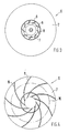
- Fig. 3 shows the impeller 6 from the suction side.
- the blades 8 on the lower part 7 can be seen through the opening 10 in the cover 2.
- Fig. 4 again shows that the blades are 8 circular sections.
- the base points of the radius of all circular sections lie on the circle 16.
- the diameter of the circle 16 is 98 mm.
Description
Die Erfindung betrifft eine Vorrichtung zum Fördern eines gasförmigen Mediums in einer Vorrichtung mit großem Strömungswiderstand.The invention relates to a device for conveying a gaseous medium in a device with high flow resistance.
Bei der Vorrichtung mit hohem Strömungswiderstand kann es sich beispielsweise um einen keramischen Flächenbrenner handeln, welche neuerdings in Gas-Heizkesseln verwendet werden. Diese Gas-Heizkessel mit keramischen Flächenbrennern sind bekannt (Zeitschrift: HLH, Heizung, Lüftung/Klima, Haustechnik; Zeitschrift des Vereins deutscher Ingenieure für technische Gebäudeausrüstung; Juni 1989, Seite 308). Sie weisen einen verhältnismäßig hohen Strömungswiderstand, welcher in der Größenordnung von 200 Pascal und mehr liegt, auf. Bei dem zu fördernden Medium kann es sich entweder um Luft oder ein brennbares Gasgemisch handeln.The device with high flow resistance can be, for example, a ceramic surface burner, which has recently been used in gas boilers. These gas boilers with ceramic surface burners are known (magazine: HLH, heating, ventilation / air conditioning, building services; magazine of the Association of German Engineers for Technical Building Equipment; June 1989, page 308). They have a relatively high flow resistance, which is on the order of 200 Pascal and more. The medium to be pumped can either be air or a combustible gas mixture.
Es ist ein Radialgebläse bekannt (CH-A-301 116), welches ein verbessertes Ventilator-Druckgehäuse zeigt. Dieses besteht aus zwei gepreßten, kalottenförmigen Gehäuseteilen, die mit ihren konkaven Seiten gegeneinandergekehrt und längs ihrer Umfangsfuge miteinander verschweißt sind. Das bekannte Gebläse besitzt ein geschlossenes Gebläserad, dessen Unterteil und Oberteil jeweils aus einer flachen tellerförmigen Platte bestehen.A radial fan is known (CH-A-301 116), which shows an improved fan pressure housing. This consists of two pressed, dome-shaped housing parts that face each other with their concave sides and are welded together along their circumferential joint. The known fan has a closed fan wheel, the lower part and upper part of which consist of a flat plate-shaped plate.
Dieses bekannte Gebläse ist - schon allein wegen seiner Abmessungen - für den Einsatz bei keramischen Flächenbrennern in Gas-Heizkesseln ungeeignet.This known fan is unsuitable - if only because of its dimensions - for use with ceramic surface burners in gas boilers.
Es ist auch ein Radialgebläse zur Förderung stark staubhaltiger Gase bekannt (DE-B-1, 204, 774), welches mit hohem Wirkungsgrad arbeiten soll. Bei diesem bekannten Radialgebläse besitzt das Gebläserad rückwärts gekrümmte Schaufeln, deren Schaufelwinkel am Laufradeintritt und am Laufradaustritt etwa gleich sind.A radial blower for conveying gases that are very dusty is also known (DE-B-1, 204, 774), which is said to work with high efficiency. In this known radial fan, the impeller has backward curved blades, the blade angles of which are approximately the same at the impeller inlet and at the impeller outlet.
Die Beschreibung dieses bekannten Radialgebläses enthält keinen Hinweis darauf, wie ein Gebläse zum Fördern eines gasförmigen Mediums in einer Vorrichtung mit großem Strömungswiderstand ausgebildet sein sollte.The description of this known radial fan contains no indication of how a fan for conveying a gaseous medium should be designed in a device with a high flow resistance.
Es ist ein weiteres Radialgebläse bekannt (FR-A-1, 396, 805), bei welchem eine Maßnahme zur Geräuschminderung durchgeführt worden ist. Sie besteht darin, daß der Spalt zwischen Gebläserad und Innenkontur des Gehäuses im Zungenbereich keilförmig ausgebildet ist. Auch der Beschreibung dieses bekannten Radialgebläses ist kein Hinweis auf die Lösung des anmeldungsgemäßen technischen Problems zu entnehmen.Another radial fan is known (FR-A-1, 396, 805), in which a measure for noise reduction has been carried out. It consists in that the gap between the impeller and the inner contour of the housing is wedge-shaped in the tongue area. In the description of this known radial fan, there is also no reference to the solution of the technical problem according to the application.
Der Erfindung liegt das technische Problem zugrunde, eine Vorrichtung zum Fördern eines gasförmigen Mediums in einer Vorrichtung mit großem Strömungswiderstand zu schaffen, d.h. bei welcher das geförderte Medium einen relativ hohen Gegendruck überwindet und welche eine steile Druck-Volumenstrom-Kennlinie aufweist, d.h. bei der Vorrichtung sollen größere Änderungen des erzeugten Drucks nur mit geringen Änderungen des Volumenstroms einhergehen. Der hohe Gegendruck soll etwa 400 bis 450 Pascal und der Volumenstrom soll etwa 7 bis 10 l/s bei einer Dichte des gasförmigen Mediums ρ = 1,2 kg/m³ betragen. Da die Geräte, in welchen die Vorrichtung verwendet wird, nicht allzu raumgreifend sein dürfen, darf die von der Vorrichtung beanspruchte Grundfläche (Höhe mal Breite) eine bestimmte Größe, beispielsweise 180 mal 180 mm, nicht überschreiten.The invention is based on the technical problem of providing a device for conveying a gaseous medium in a device with high flow resistance, i.e. at which the pumped medium overcomes a relatively high back pressure and which has a steep pressure-volume flow characteristic, i.e. in the device, major changes in the pressure generated should only be accompanied by minor changes in the volume flow. The high back pressure should be about 400 to 450 Pascal and the volume flow should be about 7 to 10 l / s with a density of the gaseous medium ρ = 1.2 kg / m³. Since the devices in which the device is used must not be too extensive, the base area (height times width) occupied by the device must not exceed a certain size, for example 180 times 180 mm.
Hinzu kommt, daß das Eigengeräusch der Vorrichtung das Eigengeräusch bekannter Vorrichtungen zum Fördern eines gasförmigen Mediums nicht überschreiten darf.In addition, the inherent noise of the device must not exceed the inherent noise of known devices for conveying a gaseous medium.
Dieses technische Problem ist erfindungsgemäß durch ein Radialgebläse mit folgenden Merkmalen gelöst:
- a) einem flachen topfförmigen Gehäuse mit einer spiralförmigen Innenkontur,
- b) einem im wesentlichen ebenen Deckel mit einer zentralen kreisförmigen Öffnung,
- c) einem geschlossenen Gebläserad, dessen Durchmesser mehr als das Zehnfache seiner Strömungsaustrittsbreite beträgt,
- d) das Gebläserad besteht aus einem im wesentlichen ebenen Unterteil, einer Mehrzahl von rückwärts gekrümmten, die Form eines Kreisabschnitts aufweisenden, Schaufeln, deren Breite am Umfang des Gebläserades geringer als an ihrem inneren Ende ist, und einem kreisförmigen, flach tellerförmigen Deckel mit einer zentralen kreisförmigen Öffnung,
- e) die Schaufeln sind derart im Gebläserad angeordnet, daß ihr Eintrittswinkel und ihr Austrittswinkel etwa den gleichen Wert aufweisen,
- f) einem keilförmig ausgebildeten Spalt im Zungenbereich zwischen Gebläserad und Innenkontur des Gehäuses.
- a) a flat pot-shaped housing with a spiral-shaped inner contour,
- b) a substantially flat lid with a central circular opening,
- c) a closed impeller, the diameter of which is more than ten times its flow outlet width,
- d) the impeller consists of a substantially flat lower part, a plurality of backward curved blades having the shape of a circular section, the width of which is less at the circumference of the impeller than at its inner end, and a circular, flat plate-shaped cover with a central one circular opening,
- e) the blades are arranged in the impeller in such a way that their entry angle and their exit angle have approximately the same value,
- f) a wedge-shaped gap in the tongue area between the impeller and the inner contour of the housing.
Bei dem erfindungsgemäßen Radialgebläse, von dem eine Ausführungsform kleiner als 170 mm im Quadrat (Höhe mal Breite) ist, weist das geförderte gasförmige Medium im vorgesehenen Betriebspunkt einen Druck von 415 Pascal und einen Volumenstrom von 6,9 l/s auf. Die Drehzahl des Gebläserades betrug etwa 3800 Umdrehungen pro Minute.In the radial fan according to the invention, one embodiment of which is smaller than 170 mm square (height times width), the pumped gaseous medium has a pressure of 415 Pascal and a volume flow of 6.9 l / s at the intended operating point. The speed of the fan wheel was about 3800 revolutions per minute.
Vorteilhafte Ausgestaltungen der Erfindung sind in den Ansprüchen 2 bis 5 enthalten. Sie ist nachstehend anhand eines in den Figuren 1 bis 4 gezeigten Ausführungsbeispieles erläutert. Es zeigen:
- Fig. 1
- den Längsschnitt durch ein Ausführungsbeispiel des erfindungsgemäßen Radialgebläses,
- Fig. 2
- die Seitenansicht des prinzipiellen Aufbaus des Radialgebläses gemäß Fig. 1,
- Fig. 3
- die Draufsicht auf die Stirnseite des Gebläserades und
- Fig. 4
- den prinzipiellen Aufbau des Gebläserades gemäß Fig. 3.
- Fig. 1
- the longitudinal section through an embodiment of the radial fan according to the invention,
- Fig. 2
- the side view of the basic structure of the radial fan according to FIG. 1,
- Fig. 3
- the top view of the front of the impeller and
- Fig. 4
- the basic structure of the impeller according to FIG. 3.
Wie in Fig. 1 zu erkennen, ist das Gehäuse 1 des Radialgebläses mit dem Deckel 2 verschlossen. Bei dem gezeigten Ausführungsbeispiel bestehen Gehäuse 1 und Deckel aus Aluminium-Spritzguß. Der Deckel 2 ist unter Zwischenschaltung einer Dichtung 3 am Rand mit dem Gehäuse 1 verschraubt. Auf der Rückseite des Gehäuses 1 ist der Antriebsmotor 4 angeflanscht, dessen Abtriebswelle 5 in das Gehäuse 1 hineinragt. Bei dem gezeigten Antriebsmotor 4 handelt es sich um einen elektronisch kommutierten Gleichstrommotor. Es kann aber auch ein Wechselstrommotor verwendet werden. Auf diesem in das Gehäuse 1 hinragenden Ende der Abtriebswelle 5 ist das Gebläserad 6 kraft- und/oder formschlüssig befestigt. Die Strömungsaustritts-Breite des Gebläserades 6 ist mit c bezeichnet. Das Gebläserad 6 besteht aus dem Unterteil 7 mit den einstückig daran befestigten Schaufeln 8 und dem Deckel 9. Bei dem gezeigten Ausführungsbeispiel ist die Länge der Schaufel 8 am unteren Ende, d.h. am Unterteil 7, größer als am oberen Ende, d.h. nahe dem Deckel 9. Das Gebläserad 6 kann aus Metall oder Kunststoff bestehen.As can be seen in FIG. 1, the housing 1 of the radial fan is closed with the
Bei dem gezeigten Radialgebläse wird das gasförmige Medium axial, d.h. durch Öffnung 10 im Deckel 2, angesaugt und radial (in Fig. 1 in die Bildebene hinein) ausgeblasen. Die Ausblasöffnung ist als rechteckige Blende in dem kreisförmigen Flansch 11 vorhanden.In the radial fan shown, the gaseous medium is sucked in axially, ie through opening 10 in the
In Fig. 2 ist die wirksame Gestalt des erfindungsgemäßen Radialgebläses verdeutlicht. Das Gehäuse 1 weist die spiralförmige Innenkontur 12 auf. In dieser Innenkontur ist das Gebläserad 6 mit den Schaufeln 8 derart angeordnet, daß sich zwischen den Punkten A und B der geringste und nahezu gleichmäßige Abstand zwischen Innenkontur 12 und Gebläserad 6 ergibt. Beim gezeigten Ausführungsbeispiel beträgt dieser Abstand 6% des Gebläseradhalbmessers (= 65 mm). Die Abmessungen a und b betragen bei dem gezeigten Ausführungsbeispiel 156 mm. Die Schaufeln 8 sind rückwärts gekrümmt, wie sich aus dem Vergleich mit der durch den Pfeil 13 verdeutlichten Drehrichtung des Gebläserades 6 ergibt.The effective shape of the radial fan according to the invention is illustrated in FIG. The housing 1 has the spiral-shaped
Die Gestalt der Schaufeln 8 entspricht im wesentlichen Kreisbögen. Sie sind in der Weise auf dem Unterteil 7 angeordnet, daß der Eintrittswinkel β₁ nahezu den gleichen Wert wie der Austrittswinkel β₂ aufweist. Bei dem gezeigten Ausführungsbeispiel haben sie den Wert von 47 Winkelgraden.The shape of the
Bei derartigen Radialgebläsen wird der Spalt zwischen Gebläserad 6 und Innenkontur 12 des Gehäuses nahe der Ausblasöffnung 14 als Zungenbereich 15 bezeichnet. Entgegen der sonst bei Radialgebläsen üblichen Ausgestaltung des Zungenbereiches ist im vorliegenden Fall der Zungenbereich keilförmig gestaltet.In the case of such radial fans, the gap between the
Fig. 3 zeigt das Gebläserad 6 von der Ansaugseite her. Durch die Öffnung 10 im Deckel 2 sind die Schaufeln 8 auf dem Unterteil 7 zu erkennen.Fig. 3 shows the
Fig. 4 verdeutlicht nochmals, daß die Schaufeln 8 Kreisabschnitte sind. Die Fußpunkte der Halbmesser aller Kreisabschnitte liegen auf dem Kreis 16. Bei einem Gebläserad 6 mit einem Außendruchmesser von 130 mm beträgt der Durchmesser des Kreises 16 98 mm.Fig. 4 again shows that the blades are 8 circular sections. The base points of the radius of all circular sections lie on the
Claims (5)
- A device for conveying a gaseous medium in a device having a high flow resistance,
characterized by a centrifugal fan with the following features:a) a flat, cup-shaped casing (1) having a spiral-shaped inner contour (12);b) an essentially plane cover (2) having a central, circular opening (10);c) a closed impeller (6) having a diameter more than ten times greater than its outlet width c);d) the impeller (6) consists of an essentially plane bottom part (7), a plurality of blades (8) which are curved backward in the form of the arc of a circle and whose width along the circumference of the impeller is less than that at their inner ends, and a circular, flat, plate-shaped cover (9) having a central, circular opening;e) the blades (8) are disposed in the impeller (6) to have an inlet angle (beta 1) and an outlet angle (beta 2) of approximately the same value;f) a wedge-shaped gap in the tongue region (15) between the impeller (6) and the inner contour (12) of the casing (1). - A centrifugal fan as claimed in claim 1,
characterized in that the length of the blades (8) at the bottom part (7) is greater than that at the cover (9). - A centrifugal fan as claimed in claims 1 and 2,
characterized in that the inlet and outlet angles (beta 1, beta 2) of the blades (8) preferably have a value between 45 and 50 degrees. - A centrifugal fan as claimed in claims 1 to 3,
characterized in that the region of the shortest distance between the impeller (6) and the inner contour (12) of the casing (1) is shifted from the tongue region (15) in the direction of rotation of the impeller (6) and extends over approximately one quarter of the circumference of the casing (between A and B). - A centrifugal fan as claimed in claims 1 to 7,
characterized in that the shortest distance between the circumference of the impeller and the inner contour (12) of the casing (1) is equal to between 4 and 8% of the impeller radius.
Applications Claiming Priority (2)
| Application Number | Priority Date | Filing Date | Title |
|---|---|---|---|
| DE3924281A DE3924281A1 (en) | 1989-07-22 | 1989-07-22 | DEVICE FOR CONVEYING A GASEOUS MEDIUM |
| DE3924281 | 1989-07-22 |
Publications (3)
| Publication Number | Publication Date |
|---|---|
| EP0410271A2 EP0410271A2 (en) | 1991-01-30 |
| EP0410271A3 EP0410271A3 (en) | 1991-08-07 |
| EP0410271B1 true EP0410271B1 (en) | 1994-09-21 |
Family
ID=6385604
Family Applications (1)
| Application Number | Title | Priority Date | Filing Date |
|---|---|---|---|
| EP90113649A Expired - Lifetime EP0410271B1 (en) | 1989-07-22 | 1990-07-17 | Feed device for gaseous medium |
Country Status (3)
| Country | Link |
|---|---|
| EP (1) | EP0410271B1 (en) |
| JP (1) | JPH0357899A (en) |
| DE (2) | DE3924281A1 (en) |
Cited By (1)
| Publication number | Priority date | Publication date | Assignee | Title |
|---|---|---|---|---|
| EP2196679A2 (en) | 2004-07-31 | 2010-06-16 | ebm-papst Landshut GmbH | Impeller for a radial fan |
Families Citing this family (13)
| Publication number | Priority date | Publication date | Assignee | Title |
|---|---|---|---|---|
| EP0516073A1 (en) * | 1991-05-29 | 1992-12-02 | Alcatel SEL Aktiengesellschaft | Apparatus for transporting a gaseous medium |
| DE4141359A1 (en) * | 1991-12-14 | 1993-06-17 | Sel Alcatel Ag | Impeller for radial-flow fan - Has numerous apertures in surface of impeller underside opposite to impeller suction aperture. |
| DE4141360A1 (en) * | 1991-12-14 | 1993-06-17 | Sel Alcatel Ag | RADIAL BLOWER FOR CONVEYING A COMBUSTIBLE GAS MIXTURE |
| DE4141362C2 (en) * | 1991-12-14 | 2002-10-24 | Motoren Ventilatoren Gmbh | Radial blower with throttle device |
| DE4242474A1 (en) * | 1992-12-16 | 1994-06-23 | Sel Alcatel Ag | Device for conveying a gaseous medium |
| DE4318580A1 (en) * | 1993-06-04 | 1994-12-08 | Sel Alcatel Ag | Radial fan |
| DE19516515A1 (en) * | 1995-05-05 | 1996-11-07 | Sel Alcatel Ag | Radial fan |
| DE19602368A1 (en) * | 1996-01-24 | 1997-07-31 | Sel Alcatel Ag | Radial fan |
| DE20012654U1 (en) * | 2000-07-19 | 2000-09-21 | Map Gmbh | Device for supplying a breathing gas |
| DE202005004180U1 (en) | 2005-03-14 | 2006-07-27 | Ebm-Papst Landshut Gmbh | centrifugal blower |
| US20110217182A1 (en) * | 2010-02-01 | 2011-09-08 | Brink Climate Systems B.V. | Air movement system |
| CN103711713B (en) * | 2012-09-28 | 2016-08-24 | 昆山广兴电子有限公司 | Centrifugal heat radiation fan |
| EP3530956B1 (en) * | 2018-02-26 | 2021-09-22 | Honeywell Technologies Sarl | Impeller for a radial fan and gas burner appliance |
Family Cites Families (5)
| Publication number | Priority date | Publication date | Assignee | Title |
|---|---|---|---|---|
| CH301116A (en) * | 1952-05-27 | 1954-08-31 | Ag Hch Bertrams | Fan pressure casing. |
| DE1204774B (en) * | 1954-01-27 | 1965-11-11 | Bruno Eck Dr Ing | Radial blower for conveying very dusty gases |
| FR1396805A (en) * | 1964-05-28 | 1965-04-23 | Svenska Flaektfabriken Ab | Housing for centrifugal fan |
| GB2055969B (en) * | 1979-07-19 | 1983-11-16 | Sgm Co Inc | Low noise centrifugal blower |
| DE3700230A1 (en) * | 1987-01-07 | 1988-07-21 | Hauni Werke Koerber & Co Kg | Fan impeller |
-
1989
- 1989-07-22 DE DE3924281A patent/DE3924281A1/en not_active Withdrawn
-
1990
- 1990-07-17 DE DE59007207T patent/DE59007207D1/en not_active Expired - Lifetime
- 1990-07-17 EP EP90113649A patent/EP0410271B1/en not_active Expired - Lifetime
- 1990-07-20 JP JP2190919A patent/JPH0357899A/en active Pending
Cited By (3)
| Publication number | Priority date | Publication date | Assignee | Title |
|---|---|---|---|---|
| EP2196679A2 (en) | 2004-07-31 | 2010-06-16 | ebm-papst Landshut GmbH | Impeller for a radial fan |
| US7794206B2 (en) | 2004-07-31 | 2010-09-14 | Emb-Papst Landshut Gmbh | Radial fan impeller |
| US8109731B2 (en) | 2004-07-31 | 2012-02-07 | Ebm-Papst Landshut Gmbh | Radial fan impeller |
Also Published As
| Publication number | Publication date |
|---|---|
| JPH0357899A (en) | 1991-03-13 |
| DE59007207D1 (en) | 1994-10-27 |
| EP0410271A2 (en) | 1991-01-30 |
| EP0410271A3 (en) | 1991-08-07 |
| DE3924281A1 (en) | 1991-01-31 |
Similar Documents
| Publication | Publication Date | Title |
|---|---|---|
| EP0410271B1 (en) | Feed device for gaseous medium | |
| EP0112932B1 (en) | Radial ventilator with backwards-curved profiled blades | |
| DE2940773C2 (en) | High-performance centrifugal fan | |
| DE2551614C2 (en) | Axial short axial fan | |
| DE2940650A1 (en) | AXIAL FAN | |
| DE2950060C2 (en) | ||
| DE4313617C2 (en) | Radial fan | |
| DE7136940U (en) | VACUUM CLEANER | |
| DE1503704C3 (en) | BLADE FOR A WHEEL AND OR GUIDE WHEEL OF A TURBOMOLECULAR PUMP | |
| EP0166174A1 (en) | Radial ventilator | |
| DE1403474A1 (en) | Centrifugal housing for fans | |
| DE3310376C2 (en) | ||
| DE4130901A1 (en) | FAN | |
| DE2136369A1 (en) | HEAT EXCHANGER UNIT, IN PARTICULAR FOR ROOM AIR CONDITIONING UNITS | |
| EP0074514B1 (en) | Arrangement of a cooler and a motor having a ventilator arranged on its shaft, especially for a screw compressor installation | |
| EP0177723B1 (en) | Radial ventilator | |
| DE2001395C3 (en) | ||
| EP0070423B1 (en) | Cooling of the electric motor of an axial ventilator | |
| DE3343752C2 (en) | ||
| DE3541787A1 (en) | FAN WITH AN ESSENTIALLY SQUARE SHAPED HOUSING | |
| DE20317171U1 (en) | Blower housing has the outer wall fitted with radial vanes to create radial inlet ducts to increase the inlet air flow and reduce noise | |
| DE900372C (en) | Impeller with adjustable blades for radial fan | |
| DE2015737C3 (en) | Device for agglomeration and precipitation of suspended matter from gases and vapors and / or for the absorption of gas components | |
| AT205410B (en) | Blower for material handling | |
| DE4412193C1 (en) | Drive motor unit for cooling fans |
Legal Events
| Date | Code | Title | Description |
|---|---|---|---|
| PUAI | Public reference made under article 153(3) epc to a published international application that has entered the european phase |
Free format text: ORIGINAL CODE: 0009012 |
|
| AK | Designated contracting states |
Kind code of ref document: A2 Designated state(s): DE FR GB IT NL |
|
| PUAL | Search report despatched |
Free format text: ORIGINAL CODE: 0009013 |
|
| AK | Designated contracting states |
Kind code of ref document: A3 Designated state(s): DE FR GB IT NL |
|
| 17P | Request for examination filed |
Effective date: 19911212 |
|
| RAP3 | Party data changed (applicant data changed or rights of an application transferred) |
Owner name: ALCATEL SEL AKTIENGESELLSCHAFT |
|
| 17Q | First examination report despatched |
Effective date: 19921216 |
|
| GRAA | (expected) grant |
Free format text: ORIGINAL CODE: 0009210 |
|
| AK | Designated contracting states |
Kind code of ref document: B1 Designated state(s): DE FR GB IT NL |
|
| REF | Corresponds to: |
Ref document number: 59007207 Country of ref document: DE Date of ref document: 19941027 |
|
| GBT | Gb: translation of ep patent filed (gb section 77(6)(a)/1977) |
Effective date: 19941018 |
|
| ITF | It: translation for a ep patent filed |
Owner name: DOTT. ANTONIO SERGI |
|
| ET | Fr: translation filed | ||
| PLBI | Opposition filed |
Free format text: ORIGINAL CODE: 0009260 |
|
| 26 | Opposition filed |
Opponent name: EBM ELEKTROBAU MULFINGEN GMBH & CO. Effective date: 19950617 |
|
| NLR1 | Nl: opposition has been filed with the epo |
Opponent name: EBM ELEKTROBAU MULFINGEN GMBH & CO. |
|
| PLBO | Opposition rejected |
Free format text: ORIGINAL CODE: EPIDOS REJO |
|
| PLBN | Opposition rejected |
Free format text: ORIGINAL CODE: 0009273 |
|
| STAA | Information on the status of an ep patent application or granted ep patent |
Free format text: STATUS: OPPOSITION REJECTED |
|
| 27O | Opposition rejected |
Effective date: 19971124 |
|
| NLR2 | Nl: decision of opposition | ||
| NLS | Nl: assignments of ep-patents |
Owner name: MOTOREN VENTILATOREN LANDSHUT GMBH |
|
| REG | Reference to a national code |
Ref country code: GB Ref legal event code: 732E |
|
| REG | Reference to a national code |
Ref country code: FR Ref legal event code: TP |
|
| REG | Reference to a national code |
Ref country code: GB Ref legal event code: IF02 |
|
| PGFP | Annual fee paid to national office [announced via postgrant information from national office to epo] |
Ref country code: FR Payment date: 20090716 Year of fee payment: 20 |
|
| PGFP | Annual fee paid to national office [announced via postgrant information from national office to epo] |
Ref country code: NL Payment date: 20090730 Year of fee payment: 20 Ref country code: GB Payment date: 20090720 Year of fee payment: 20 |
|
| PGFP | Annual fee paid to national office [announced via postgrant information from national office to epo] |
Ref country code: DE Payment date: 20090928 Year of fee payment: 20 |
|
| PGFP | Annual fee paid to national office [announced via postgrant information from national office to epo] |
Ref country code: IT Payment date: 20090723 Year of fee payment: 20 |
|
| REG | Reference to a national code |
Ref country code: NL Ref legal event code: V4 Effective date: 20100717 |
|
| REG | Reference to a national code |
Ref country code: GB Ref legal event code: PE20 Expiry date: 20100716 |
|
| PG25 | Lapsed in a contracting state [announced via postgrant information from national office to epo] |
Ref country code: NL Free format text: LAPSE BECAUSE OF EXPIRATION OF PROTECTION Effective date: 20100717 |
|
| PG25 | Lapsed in a contracting state [announced via postgrant information from national office to epo] |
Ref country code: GB Free format text: LAPSE BECAUSE OF EXPIRATION OF PROTECTION Effective date: 20100716 |
|
| PG25 | Lapsed in a contracting state [announced via postgrant information from national office to epo] |
Ref country code: DE Free format text: LAPSE BECAUSE OF EXPIRATION OF PROTECTION Effective date: 20100717 |