EP0409579B1 - Movement controlling strut - Google Patents
Movement controlling strut Download PDFInfo
- Publication number
- EP0409579B1 EP0409579B1 EP19900307824 EP90307824A EP0409579B1 EP 0409579 B1 EP0409579 B1 EP 0409579B1 EP 19900307824 EP19900307824 EP 19900307824 EP 90307824 A EP90307824 A EP 90307824A EP 0409579 B1 EP0409579 B1 EP 0409579B1
- Authority
- EP
- European Patent Office
- Prior art keywords
- chambers
- strut
- fluid pressure
- pair
- movement
- Prior art date
- Legal status (The legal status is an assumption and is not a legal conclusion. Google has not performed a legal analysis and makes no representation as to the accuracy of the status listed.)
- Expired - Lifetime
Links
- 239000012530 fluid Substances 0.000 claims description 44
- 238000004891 communication Methods 0.000 claims description 30
- 230000000903 blocking effect Effects 0.000 claims description 5
- 230000005540 biological transmission Effects 0.000 claims description 3
- 230000007423 decrease Effects 0.000 claims 1
- 238000013016 damping Methods 0.000 description 13
- 239000012528 membrane Substances 0.000 description 12
- 238000012546 transfer Methods 0.000 description 6
- 238000001914 filtration Methods 0.000 description 5
- 230000000694 effects Effects 0.000 description 4
- 230000036316 preload Effects 0.000 description 4
- 238000005266 casting Methods 0.000 description 2
- 230000004888 barrier function Effects 0.000 description 1
- 230000015572 biosynthetic process Effects 0.000 description 1
- 239000000872 buffer Substances 0.000 description 1
- 230000015556 catabolic process Effects 0.000 description 1
- 230000001413 cellular effect Effects 0.000 description 1
- 238000006731 degradation reaction Methods 0.000 description 1
- 238000013461 design Methods 0.000 description 1
- 239000007788 liquid Substances 0.000 description 1
- 238000005259 measurement Methods 0.000 description 1
- 239000002184 metal Substances 0.000 description 1
- 238000012986 modification Methods 0.000 description 1
- 230000004048 modification Effects 0.000 description 1
- 230000010363 phase shift Effects 0.000 description 1
Images



Classifications
-
- F—MECHANICAL ENGINEERING; LIGHTING; HEATING; WEAPONS; BLASTING
- F16—ENGINEERING ELEMENTS AND UNITS; GENERAL MEASURES FOR PRODUCING AND MAINTAINING EFFECTIVE FUNCTIONING OF MACHINES OR INSTALLATIONS; THERMAL INSULATION IN GENERAL
- F16F—SPRINGS; SHOCK-ABSORBERS; MEANS FOR DAMPING VIBRATION
- F16F13/00—Units comprising springs of the non-fluid type as well as vibration-dampers, shock-absorbers, or fluid springs
- F16F13/04—Units comprising springs of the non-fluid type as well as vibration-dampers, shock-absorbers, or fluid springs comprising both a plastics spring and a damper, e.g. a friction damper
- F16F13/06—Units comprising springs of the non-fluid type as well as vibration-dampers, shock-absorbers, or fluid springs comprising both a plastics spring and a damper, e.g. a friction damper the damper being a fluid damper, e.g. the plastics spring not forming a part of the wall of the fluid chamber of the damper
- F16F13/08—Units comprising springs of the non-fluid type as well as vibration-dampers, shock-absorbers, or fluid springs comprising both a plastics spring and a damper, e.g. a friction damper the damper being a fluid damper, e.g. the plastics spring not forming a part of the wall of the fluid chamber of the damper the plastics spring forming at least a part of the wall of the fluid chamber of the damper
- F16F13/14—Units of the bushing type, i.e. loaded predominantly radially
-
- B—PERFORMING OPERATIONS; TRANSPORTING
- B60—VEHICLES IN GENERAL
- B60K—ARRANGEMENT OR MOUNTING OF PROPULSION UNITS OR OF TRANSMISSIONS IN VEHICLES; ARRANGEMENT OR MOUNTING OF PLURAL DIVERSE PRIME-MOVERS IN VEHICLES; AUXILIARY DRIVES FOR VEHICLES; INSTRUMENTATION OR DASHBOARDS FOR VEHICLES; ARRANGEMENTS IN CONNECTION WITH COOLING, AIR INTAKE, GAS EXHAUST OR FUEL SUPPLY OF PROPULSION UNITS IN VEHICLES
- B60K5/00—Arrangement or mounting of internal-combustion or jet-propulsion units
- B60K5/12—Arrangement of engine supports
- B60K5/1241—Link-type support
-
- F—MECHANICAL ENGINEERING; LIGHTING; HEATING; WEAPONS; BLASTING
- F16—ENGINEERING ELEMENTS AND UNITS; GENERAL MEASURES FOR PRODUCING AND MAINTAINING EFFECTIVE FUNCTIONING OF MACHINES OR INSTALLATIONS; THERMAL INSULATION IN GENERAL
- F16F—SPRINGS; SHOCK-ABSORBERS; MEANS FOR DAMPING VIBRATION
- F16F13/00—Units comprising springs of the non-fluid type as well as vibration-dampers, shock-absorbers, or fluid springs
- F16F13/04—Units comprising springs of the non-fluid type as well as vibration-dampers, shock-absorbers, or fluid springs comprising both a plastics spring and a damper, e.g. a friction damper
- F16F13/26—Units comprising springs of the non-fluid type as well as vibration-dampers, shock-absorbers, or fluid springs comprising both a plastics spring and a damper, e.g. a friction damper characterised by adjusting or regulating devices responsive to exterior conditions
- F16F13/28—Units comprising springs of the non-fluid type as well as vibration-dampers, shock-absorbers, or fluid springs comprising both a plastics spring and a damper, e.g. a friction damper characterised by adjusting or regulating devices responsive to exterior conditions specially adapted for units of the bushing type
-
- F—MECHANICAL ENGINEERING; LIGHTING; HEATING; WEAPONS; BLASTING
- F16—ENGINEERING ELEMENTS AND UNITS; GENERAL MEASURES FOR PRODUCING AND MAINTAINING EFFECTIVE FUNCTIONING OF MACHINES OR INSTALLATIONS; THERMAL INSULATION IN GENERAL
- F16F—SPRINGS; SHOCK-ABSORBERS; MEANS FOR DAMPING VIBRATION
- F16F15/00—Suppression of vibrations in systems; Means or arrangements for avoiding or reducing out-of-balance forces, e.g. due to motion
- F16F15/02—Suppression of vibrations of non-rotating, e.g. reciprocating systems; Suppression of vibrations of rotating systems by use of members not moving with the rotating systems
- F16F15/023—Suppression of vibrations of non-rotating, e.g. reciprocating systems; Suppression of vibrations of rotating systems by use of members not moving with the rotating systems using fluid means
Definitions
- the invention relates to a strut for controlling movement between two bodies between which it extends in use, comprising a first support flexibly supported on the strut for receiving a first member connected to one body, a second support flexibly supported on the strut for receiving a second member connected to the other body, chambers containing hydraulic fluid and respectively associated with the first and second supports such that movement of each support relative to the strut changes the effective volumes of the chambers, and a fluid pressure communication arrangement placing the chambers respectively associated with the first and second supports in fluid pressure communication with each other, such that movement of each of the supports relative to the strut causes a corresponding pressure to be transmitted by the fluid flow communication arrangement to oppose any consequent movement of the other of the supports relative to the strut.
- Such a strut is shown in DE-A-3 529 199.
- a pipe continuously connects the chambers respectively associated with the first and second supports.
- the fluid pressure communication arrangement comprises separate fluid pressure communication channels connected, in parallel with each other, between the chambers respectively associated with the first and second supports.
- the strut as first set forth above is characterised in that at least one of the fluid pressure communication channels incorporates a control device selectively operable to switch that channel out of operation by blocking transmission of fluid pressure therealong, and at least one other of the fluid pressure communication channels providing continuous communication between the chambers respectively associated with the first and second supports.
- the struts to be described are used for limiting the amplitude of the movement of a motor vehicle engine and a vehicle body. Normally, such an engine is elastically carried by flexible supports such as made of rubber.
- a movement-limiting strut such as shown at 5 in Figures 1 and 2.
- the vehicle engine is shown at 6 and is supported by flexible supports 8, incorporating rubber, on chassis or body members 10.
- the strut 5 comprises pins 12 and 14 connected together by a rigid extension 16.
- Each pin is mounted within a respective end of the strut by means of a respective rubber sleeve or similar structure.
- the rubber sleeves or structures are made of cellular rubber ensuring relatively high flexibility and thus providing good filtering of high-frequency, low-amplitude vibrations of the engine.
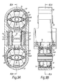
- the movement-limiting strut shown in Figures 3A and 3B (which illustrate the strut turned through a right angle as compared with Figure 2) has a central rigid arm arrangement 54,56 (to be described below) which is connected to two rigid open ended cylinders 50,52 in the form of castings.
- a rubber structure 24 mounted within each cylinder 50,52 is a rubber structure 24 in the form of a closed cylindrical rubber membrane integral with a rubber dividing wall 24B.
- the latter centrally support a metal sleeve 26.
- the rubber membranes thus define two closed and separate hollow chambers 28 and 30 at one end of the rod and two similar closed and separate chambers 32 and 34 at the other end.
- pins corresponding to pins 12 and 14 respectively pass through the two sleeves 26 and are secured to the engine and the body respectively.
- Chambers 28,30,32,34 are filled with hydraulic fluid.
- Chamber 28 is in fluid communication with chamber 34 via a connecting channel 58
- chamber 30 is in fluid communication with chamber 32 via a channel 60.
- Channels 58 and 60 are formed as helical passageways in the rigid members 54 and 56 which are secured to the castings 50 and 52 by means not shown.
- a hollow cylinder is formed between the two members 54 and 56 by means of a flexible cylindrical membrane 70. At one end, this cylinder is in fluid connection with chamber 30 and at its other end it is in fluid communication with chamber 34.
- a piston 72 is slidable within the cylindrical membrane 70.
- vibration of the engine relative to the body causes the connecting walls 24B between pairs of chambers at each end of the strut 20 to flex in a generally vertical direction as viewed in the Figures.
- fluid circulates between chamber 28 and chamber 34 through channel 58, and between chamber 30 and chamber 32 through channel 60.
- a transfer of fluid pressure between these chambers occurs as piston 72 slides within the cylindrical membrane 70. This transfer of fluid pressure takes place at the same time as the transfer of fluid through channels 58 and 60.
- the passageways 58,60 can be formed by helically arranged channels and a central barrier around which the fluid circulates.
- the helical formation of the passageways 58 and 60 enables their lengths to be adjusted to give the appropriate characteristics.
- the flow of hydraulic fluid along the channels produces a low frequency phase shift.
- Figure 4a shows two curves of the relationship between damping, plotted on the vertical axis, against frequency of vibration plotted along the horizontal axis - but assuming that the fluid communication between chambers 30 and 34 via the cylindrical membrane 70 is completely ineffective.
- damping is represented by loss factor L while in the lower curve, it is represented by dynamic stiffness D.
- the curves shown in Figure 4a were obtained by measurements based on a vibration amplitude of plus or minus one millimetre and it is assumed that there is no preload on the strut. As shown, the damping is very effective, reaching a maximum at a very low vibration frequency (about 3 Hz).
- Figure 4b shows the corresponding curves (again for vibration amplitudes of plus or minus 1mm) when a significant preload is applied to the strut, as by the permanent torque of the running engine.
- a comparison of Figures 4a and 4b shows that the effect of this preload is to reduce the maximum damping and to cause it to occur at a significantly higher frequency (about 34Hz). Obviously, it is desirable to limit the amount by which the maximum damping is reduced, and the frequency at which the maximum damping occurs is increased, when preload occurs.
- Figures 5A and 5B show an arrangement corresponding generally to that shown in Figures 3A and 3B.
- the chamber formed by cylindrical membrane 70A is in fluid communication at its respective ends with chambers 30 and 32, while the chamber formed by cylindrical membrane 70B is in fluid communication at its respective ends with chambers 28 and 34.
- Pistons 72A and 72B can be independently locked against movement by increasing the pressure within respective channels 74A and 74B.
- the arrangement in Figures 5A and 5B therefore provides additional control compared with that of Figures 3A and 3B.
Landscapes
- Engineering & Computer Science (AREA)
- General Engineering & Computer Science (AREA)
- Mechanical Engineering (AREA)
- Physics & Mathematics (AREA)
- Acoustics & Sound (AREA)
- Aviation & Aerospace Engineering (AREA)
- Chemical & Material Sciences (AREA)
- Combustion & Propulsion (AREA)
- Transportation (AREA)
- Combined Devices Of Dampers And Springs (AREA)
- Arrangement Or Mounting Of Propulsion Units For Vehicles (AREA)
- Vehicle Body Suspensions (AREA)
Description
- The invention relates to a strut for controlling movement between two bodies between which it extends in use, comprising a first support flexibly supported on the strut for receiving a first member connected to one body, a second support flexibly supported on the strut for receiving a second member connected to the other body, chambers containing hydraulic fluid and respectively associated with the first and second supports such that movement of each support relative to the strut changes the effective volumes of the chambers, and a fluid pressure communication arrangement placing the chambers respectively associated with the first and second supports in fluid pressure communication with each other, such that movement of each of the supports relative to the strut causes a corresponding pressure to be transmitted by the fluid flow communication arrangement to oppose any consequent movement of the other of the supports relative to the strut.
- Such a strut is shown in DE-A-3 529 199. In this arrangement, a pipe continuously connects the chambers respectively associated with the first and second supports. A similar arrangement is shown in EP-A1-0 192 380, where the fluid pressure communication arrangement comprises separate fluid pressure communication channels connected, in parallel with each other, between the chambers respectively associated with the first and second supports.
- However, although such arrangements may provide adequate damping and certain frequencies, the damping provided may not be satisfactory over the whole of the frequency range in which vibrations can occur. The invention aims to overcome this problem.
- Accordingly, the strut as first set forth above is characterised in that at least one of the fluid pressure communication channels incorporates a control device selectively operable to switch that channel out of operation by blocking transmission of fluid pressure therealong, and at least one other of the fluid pressure communication channels providing continuous communication between the chambers respectively associated with the first and second supports.
- Movement-controlling struts embodying the invention for damping movement of a motor vehicle engine relative to the body on which it is supported will now be described, by way of example only, with reference to the accompanying diagrammatic drawings in which:-
- Figure 1 is a diagrammatic perspective view showing an engine supported in a motor vehicle body and illustrating a known form of movement-limiting strut;
- Figure 2 is an end view of part of Figure 1, showing the known movement-limiting strut;
- Figure 3A is a cross-section on the line IIIA-IIIA of Figure 3B and showing one of the movement-limiting struts embodying the invention;
- Figure 3B is a partial section on the line IIIB-IIIB of Figure 3A;
- Figures 4a and 4b are curves illustrating the performance of the movement-limiting strut of Figures 3A and 3B but on the assumption that one of its fluid communication channels is ineffective; and
- Figures 5A and 5B correspond to Figures 3A and 3B respectively but showing a further modification.
- The struts to be described are used for limiting the amplitude of the movement of a motor vehicle engine and a vehicle body. Normally, such an engine is elastically carried by flexible supports such as made of rubber.
- These supports permit movement of the engine relative to the vehicle body under the influence of various stresses, and, in particular, under the influence of sudden variations of engine torque. In order to control such relative movement, it is known to use a movement-limiting strut such as shown at 5 in Figures 1 and 2. In these Figures, the vehicle engine is shown at 6 and is supported by
flexible supports 8, incorporating rubber, on chassis orbody members 10. As shown in Figure 2, thestrut 5 comprisespins rigid extension 16. Each pin is mounted within a respective end of the strut by means of a respective rubber sleeve or similar structure. In such known forms, the rubber sleeves or structures are made of cellular rubber ensuring relatively high flexibility and thus providing good filtering of high-frequency, low-amplitude vibrations of the engine. However, when the engine torque changes substantially (when a sudden load is applied to or by the engine for example), the cells of the rubber become deformed and closed. The effect of this is to increase the overall rigidity of the strut, thus preventing or severely limiting movement of the engine. Filtration of the engine's vibrations becomes very poor and they are transmitted to the body. If thepins - The movement-limiting strut shown in Figures 3A and 3B (which illustrate the strut turned through a right angle as compared with Figure 2) has a central
rigid arm arrangement 54,56 (to be described below) which is connected to two rigid openended cylinders cylinder rubber structure 24 in the form of a closed cylindrical rubber membrane integral with arubber dividing wall 24B. The latter centrally support ametal sleeve 26. The rubber membranes thus define two closed and separatehollow chambers separate chambers - In use, pins corresponding to
pins 12 and 14 (see Figure 2) respectively pass through the twosleeves 26 and are secured to the engine and the body respectively. - The
chambers Chamber 28 is in fluid communication withchamber 34 via a connectingchannel 58, whilechamber 30 is in fluid communication withchamber 32 via achannel 60.Channels rigid members castings - In addition, and as shown in Figure 3A, a hollow cylinder is formed between the two
members cylindrical membrane 70. At one end, this cylinder is in fluid connection withchamber 30 and at its other end it is in fluid communication withchamber 34. Apiston 72 is slidable within thecylindrical membrane 70. - In use, vibration of the engine relative to the body causes the connecting
walls 24B between pairs of chambers at each end of the strut 20 to flex in a generally vertical direction as viewed in the Figures. As such deformation takes place, fluid circulates betweenchamber 28 andchamber 34 throughchannel 58, and betweenchamber 30 andchamber 32 throughchannel 60. In addition, when the relative volumes ofchambers piston 72 slides within thecylindrical membrane 70. This transfer of fluid pressure takes place at the same time as the transfer of fluid throughchannels - By appropriately controlling the lengths of the
channels walls 24B and there will thus be a continuing difference between the effective volumes of the two chambers at each end of the strut while the engine is running. This is compensated for by the resulting transfer of hydraulic fluid through thechannels - The
passageways - The helical formation of the
passageways - Figure 4a shows two curves of the relationship between damping, plotted on the vertical axis, against frequency of vibration plotted along the horizontal axis - but assuming that the fluid communication between
chambers cylindrical membrane 70 is completely ineffective. - In the upper curve, damping is represented by loss factor L while in the lower curve, it is represented by dynamic stiffness D. The curves shown in Figure 4a were obtained by measurements based on a vibration amplitude of plus or minus one millimetre and it is assumed that there is no preload on the strut. As shown, the damping is very effective, reaching a maximum at a very low vibration frequency (about 3 Hz).
- Figure 4b shows the corresponding curves (again for vibration amplitudes of plus or minus 1mm) when a significant preload is applied to the strut, as by the permanent torque of the running engine. A comparison of Figures 4a and 4b shows that the effect of this preload is to reduce the maximum damping and to cause it to occur at a significantly higher frequency (about 34Hz). Obviously, it is desirable to limit the amount by which the maximum damping is reduced, and the frequency at which the maximum damping occurs is increased, when preload occurs.
- However, at certain frequencies, "hydraulic lock" will occur in the
communication channels cylindrical membrane 70 is concerned with overcoming this problem. - Normally, transfer of fluid pressure between
chambers cylindrical member 70. However, thepiston 72 can be locked against movement. This is achieved by arranging formembrane 70 to bridge over achamber 74 formed by a shallow channel which is cut in the connectingmembers chamber 74 can be varied such as by transferring a gas or liquid to or from this chamber. When the pressure in thechamber 74 is increased, themembrane 70 flexes and locks thepiston 72 against further movement. Transfer of fluid pressure betweenchambers - As shown in Figure 3A at 62, excessive movements of the
flexible walls 24B are prevented by rubber buffers. - Figures 5A and 5B show an arrangement corresponding generally to that shown in Figures 3A and 3B. However, in this case there are two
cylindrical membranes slidable piston cylindrical membrane 70A is in fluid communication at its respective ends withchambers cylindrical membrane 70B is in fluid communication at its respective ends withchambers Pistons respective channels
Claims (9)
- A strut for controlling movement between two bodies (6,10) between which it extends in use, comprising a first support (26) flexibly supported on the strut (5) for receiving a first member (12) connected to one body, a second support (26) flexibly supported on the strut (5) for receiving a second member (14) connected to the other body (10), chambers (28,30,32,34) containing hydraulic fluid and respectively associated with the first and second supports (26,26) such that movement of each support (26,26) relative to the strut (5) changes the effective volumes of the chambers (28,30,32,34), and a fluid pressure communication arrangement (58,60,70,70A,70B) placing the chambers (28 and 30;32 and 34) respectively associated with the first and second supports (26,26) in fluid pressure communication with each other, such that movement of each of the supports (26,26) relative to the strut (5) causes a corresponding pressure to be transmitted by the fluid flow communication arrangement (58,60,70,70A,70B) to oppose any consequent movement of the other of the supports (26,26) relative to the strut (5), the fluid pressure communication arrangement comprising separate fluid pressure communication channels (58,60;70;70A,70B) connected, in parallel with each other, between the chambers (28,30,32,34) respectively associated with the first and second supports (26,26), characterised in that at least one (70;70A;70B) of the fluid pressure communication channels incorporates a control device (72;72A;72B) selectively operable to switch that channel (70;70A,70B) out of operation by blocking transmission of fluid pressure therealong, and at least one other (58,60) of the fluid pressure communication channels providing continuous communication between the chambers (28,30,32,34) respectively associated with the first and second supports (26,26).
- A strut according to claim 2, characterised in that the said one other of the channels (58,60) providing the continuous communication is a helically shaped channel.
- A strut according to claim 1, characterised in that there is a respective pair of chambers (28 and 30; 32 and 34) associated with each support (26,26) such that movement of each support (26,26) relative to the strut (5) increases the volume of one of the pair of chambers (28 and 30; or 32 and 34) associated with that support (26) and decreases the volume of the other of that pair of chambers (28 and 30; or 32 and 34), and in that there are two said other fluid pressure communication channels, one being a first pipe (58) continuously connecting one (28) of one pair (28,30) of the chambers with the corresponding one (34) of the other pair (32,34) of the chambers, and the other being a second pipe (60) continuously connecting the other (30) of one pair (28,30) of the chambers with the corresponding other one (32) of the other pair (32,34) of chambers.
- A strut according to claim 3, characterised in that each of the pipes (58,60) is helical.
- A strut according to claim 3 or 4, characterised in that the chambers of each pair (28,30;32,34) are separated by respective flexible walls (24B,24B) carrying the respective supports (26,26) such that each flexible wall (24B,24B) flexes with respect to the strut (5) as the corresponding support (26,26) moves relative to the strut (5).
- A strut according to claim 5, characterised by stops (62,64,66) for limiting movement of the flexible walls (24B,24B) relative to the strut.
- A strut according to any preceding claim, characterised in that the said one fluid pressure communication channel (70;70A,70B) includes an open-ended flexible-walled cylinder for transmitting the said fluid pressure, and in that the control device comprises a piston (72;72A,72B) slidable within the flexible-walled cylinder and a device (74;74A,74B) for controllably distorting the flexible wall (70;70A,70B) for blocking movement of the piston (72;72A,72B).
- A strut according to any one of claims 4 to 6, characterised in that the fluid pressure communication channels include a further fluid pressure communication channel having a control device (72B) selectively operable to switch that channel (70B) out of operation by blocking transmission of fluid pressure therealong (70B), the said one (70A) channel connecting one of one pair of the chambers (28,30) with the corresponding one of the other pair of chambers (32,34), and the said further channel (70B) connecting the other of one pair of the chambers (28,30) with the corresponding other one of the other pair of chambers (32,34).
- A strut according to claim 8, characterised in that each of the said one (70A) and the said further (70B) fluid pressure communicating channels comprises a respective open-ended flexible-walled cylinder (70A,70B) for transmitting the said fluid pressure, and in that the control device of each such channel comprises a piston (72A,72B) slidable within each flexible-walled cylinder (70A,70B) and a device (74A,74B) for controllably distorting the flexible wall (70A,70B) for blocking movement of the piston (72A,72B).
Applications Claiming Priority (2)
| Application Number | Priority Date | Filing Date | Title |
|---|---|---|---|
| GB8916619A GB2234317B (en) | 1989-07-20 | 1989-07-20 | Movement controlling strut |
| GB8916619 | 1989-07-20 |
Publications (3)
| Publication Number | Publication Date |
|---|---|
| EP0409579A2 EP0409579A2 (en) | 1991-01-23 |
| EP0409579A3 EP0409579A3 (en) | 1991-02-06 |
| EP0409579B1 true EP0409579B1 (en) | 1994-03-09 |
Family
ID=10660347
Family Applications (1)
| Application Number | Title | Priority Date | Filing Date |
|---|---|---|---|
| EP19900307824 Expired - Lifetime EP0409579B1 (en) | 1989-07-20 | 1990-07-17 | Movement controlling strut |
Country Status (5)
| Country | Link |
|---|---|
| EP (1) | EP0409579B1 (en) |
| DE (1) | DE69007195T2 (en) |
| ES (1) | ES2052178T3 (en) |
| GB (1) | GB2234317B (en) |
| PT (1) | PT94763B (en) |
Families Citing this family (9)
| Publication number | Priority date | Publication date | Assignee | Title |
|---|---|---|---|---|
| US5413320A (en) * | 1993-06-17 | 1995-05-09 | Lord Corporation | Fluid mount for devices such as engines |
| GB2298260B (en) * | 1995-02-23 | 1998-04-08 | Draftex Ind Ltd | Vibration-damping link |
| RU2150621C1 (en) * | 1998-10-13 | 2000-06-10 | Василенко Николай Васильевич | Oscillation damper |
| RU2162175C2 (en) * | 1998-10-13 | 2001-01-20 | Российский Федеральный Ядерный Центр - Всероссийский Научно-Исследовательский Институт Экспериментальной Физики | Hydraulic stop |
| RU2166677C2 (en) * | 1999-01-05 | 2001-05-10 | Открытое акционерное общество "Авиадвигатель" | Elastic-damping support |
| RU2153611C1 (en) * | 1999-01-25 | 2000-07-27 | Открытое акционерное общество "Авиадвигатель" | Elastic-damper supporting unit of gas-turbine engine |
| DE10117587A1 (en) * | 2001-04-07 | 2002-10-10 | Volkswagen Ag | Pendulum support for an assembly in a motor vehicle |
| RU2215232C2 (en) * | 2001-08-09 | 2003-10-27 | Щенёв Борис Александрович | Adjustable hydraulic damper |
| DE102015219270A1 (en) * | 2015-10-06 | 2017-04-06 | Bayerische Motoren Werke Aktiengesellschaft | Storage of a drive unit in a motor vehicle |
Family Cites Families (3)
| Publication number | Priority date | Publication date | Assignee | Title |
|---|---|---|---|---|
| US4616846A (en) * | 1984-08-14 | 1986-10-14 | Honda Giken Kogyo Kabushiki Kaisha | Control device for a suspension |
| DE3529199A1 (en) * | 1984-08-16 | 1986-02-27 | Nissan Motor Co., Ltd., Yokohama, Kanagawa | VIBRATION DAMPING SYSTEM |
| GB8503144D0 (en) * | 1985-02-07 | 1985-03-13 | Avon Ind Polymers | Hydraulically damped mounting device |
-
1989
- 1989-07-20 GB GB8916619A patent/GB2234317B/en not_active Expired - Fee Related
-
1990
- 1990-07-17 EP EP19900307824 patent/EP0409579B1/en not_active Expired - Lifetime
- 1990-07-17 DE DE1990607195 patent/DE69007195T2/en not_active Expired - Fee Related
- 1990-07-17 ES ES90307824T patent/ES2052178T3/en not_active Expired - Lifetime
- 1990-07-19 PT PT9476390A patent/PT94763B/en not_active IP Right Cessation
Also Published As
| Publication number | Publication date |
|---|---|
| DE69007195T2 (en) | 1994-09-15 |
| GB2234317B (en) | 1993-03-24 |
| PT94763B (en) | 1997-12-31 |
| GB8916619D0 (en) | 1989-09-06 |
| GB2234317A (en) | 1991-01-30 |
| ES2052178T3 (en) | 1994-07-01 |
| PT94763A (en) | 1992-06-30 |
| EP0409579A3 (en) | 1991-02-06 |
| DE69007195D1 (en) | 1994-04-14 |
| EP0409579A2 (en) | 1991-01-23 |
Similar Documents
| Publication | Publication Date | Title |
|---|---|---|
| US5172893A (en) | Hydraulic antivibratory sleeves | |
| US7478708B2 (en) | Shock absorber | |
| US4784378A (en) | Vibrating body mounting assembly | |
| US4749173A (en) | Fluid-filled resilient bushing having damping means within fluid chambers | |
| US4420060A (en) | Engine mount arrangement | |
| EP0409579A2 (en) | Movement controlling strut | |
| US5320332A (en) | Vibration damper with axial caps and diaphragm-edge areas | |
| JP2583145B2 (en) | Fluid filled type vibration damping device | |
| US4813513A (en) | Suspension device for the body and the power unit of a motor vehicle | |
| EP0524665A2 (en) | Fluid filled elastomeric damping device | |
| JP3607893B2 (en) | Hydraulic bearing | |
| JP2532076B2 (en) | Inner / outer cylinder type fluid filled power unit mount | |
| EP0623197B1 (en) | Elasto-hydraulic vibration isolator | |
| JPH01153833A (en) | Sleeve type rubber shock absorber | |
| GB2239072A (en) | A hydraulic damper arrangement | |
| US6050554A (en) | Vibration damping assemblies | |
| EP0728959B1 (en) | Vibration-damping link | |
| JP4215221B2 (en) | Hydraulic insulator | |
| JPH04244630A (en) | Hydraulic shock absorbing support | |
| EP0822352A1 (en) | Vibration damping assemblies | |
| JPH0629637B2 (en) | Anti-vibration link device with fluid | |
| US5305991A (en) | Hydraulically damped sleeve bearing | |
| JPH0545810B2 (en) | ||
| GB2318168A (en) | Hydraulically damped mounting device | |
| US5356122A (en) | Hydraulically damped bearing for a piston engine having a relief valve for insulating engine idling vibrations |
Legal Events
| Date | Code | Title | Description |
|---|---|---|---|
| PUAI | Public reference made under article 153(3) epc to a published international application that has entered the european phase |
Free format text: ORIGINAL CODE: 0009012 |
|
| PUAL | Search report despatched |
Free format text: ORIGINAL CODE: 0009013 |
|
| AK | Designated contracting states |
Kind code of ref document: A2 Designated state(s): BE DE ES FR IT SE |
|
| AK | Designated contracting states |
Kind code of ref document: A3 Designated state(s): BE DE ES FR IT SE |
|
| 17P | Request for examination filed |
Effective date: 19910628 |
|
| 17Q | First examination report despatched |
Effective date: 19930202 |
|
| GRAA | (expected) grant |
Free format text: ORIGINAL CODE: 0009210 |
|
| AK | Designated contracting states |
Kind code of ref document: B1 Designated state(s): BE DE ES FR IT SE |
|
| PG25 | Lapsed in a contracting state [announced via postgrant information from national office to epo] |
Ref country code: IT Free format text: LAPSE BECAUSE OF FAILURE TO SUBMIT A TRANSLATION OF THE DESCRIPTION OR TO PAY THE FEE WITHIN THE PRESCRIBED TIME-LIMIT;WARNING: LAPSES OF ITALIAN PATENTS WITH EFFECTIVE DATE BEFORE 2007 MAY HAVE OCCURRED AT ANY TIME BEFORE 2007. THE CORRECT EFFECTIVE DATE MAY BE DIFFERENT FROM THE ONE RECORDED. Effective date: 19940309 Ref country code: SE Free format text: THE PATENT HAS BEEN ANNULLED BY A DECISION OF A NATIONAL AUTHORITY Effective date: 19940309 Ref country code: BE Effective date: 19940309 |
|
| REF | Corresponds to: |
Ref document number: 69007195 Country of ref document: DE Date of ref document: 19940414 |
|
| REG | Reference to a national code |
Ref country code: ES Ref legal event code: FG2A Ref document number: 2052178 Country of ref document: ES Kind code of ref document: T3 |
|
| ET | Fr: translation filed | ||
| PLBE | No opposition filed within time limit |
Free format text: ORIGINAL CODE: 0009261 |
|
| STAA | Information on the status of an ep patent application or granted ep patent |
Free format text: STATUS: NO OPPOSITION FILED WITHIN TIME LIMIT |
|
| 26N | No opposition filed | ||
| PGFP | Annual fee paid to national office [announced via postgrant information from national office to epo] |
Ref country code: DE Payment date: 19950710 Year of fee payment: 6 |
|
| PGFP | Annual fee paid to national office [announced via postgrant information from national office to epo] |
Ref country code: ES Payment date: 19950727 Year of fee payment: 6 |
|
| PG25 | Lapsed in a contracting state [announced via postgrant information from national office to epo] |
Ref country code: ES Free format text: LAPSE BECAUSE OF EXPIRATION OF PROTECTION Effective date: 19960718 |
|
| PG25 | Lapsed in a contracting state [announced via postgrant information from national office to epo] |
Ref country code: DE Effective date: 19970402 |
|
| REG | Reference to a national code |
Ref country code: FR Ref legal event code: CA |
|
| REG | Reference to a national code |
Ref country code: ES Ref legal event code: FD2A Effective date: 19990601 |
|
| PGFP | Annual fee paid to national office [announced via postgrant information from national office to epo] |
Ref country code: FR Payment date: 20030721 Year of fee payment: 14 |
|
| PG25 | Lapsed in a contracting state [announced via postgrant information from national office to epo] |
Ref country code: FR Free format text: LAPSE BECAUSE OF NON-PAYMENT OF DUE FEES Effective date: 20050331 |
|
| REG | Reference to a national code |
Ref country code: FR Ref legal event code: ST |