EP0409574A2 - Optical information recording and reproducing apparatus - Google Patents
Optical information recording and reproducing apparatus Download PDFInfo
- Publication number
- EP0409574A2 EP0409574A2 EP90307818A EP90307818A EP0409574A2 EP 0409574 A2 EP0409574 A2 EP 0409574A2 EP 90307818 A EP90307818 A EP 90307818A EP 90307818 A EP90307818 A EP 90307818A EP 0409574 A2 EP0409574 A2 EP 0409574A2
- Authority
- EP
- European Patent Office
- Prior art keywords
- error signal
- tracking
- servo control
- reproducing apparatus
- optical information
- Prior art date
- Legal status (The legal status is an assumption and is not a legal conclusion. Google has not performed a legal analysis and makes no representation as to the accuracy of the status listed.)
- Granted
Links
Images


Classifications
-
- G—PHYSICS
- G11—INFORMATION STORAGE
- G11B—INFORMATION STORAGE BASED ON RELATIVE MOVEMENT BETWEEN RECORD CARRIER AND TRANSDUCER
- G11B7/00—Recording or reproducing by optical means, e.g. recording using a thermal beam of optical radiation by modifying optical properties or the physical structure, reproducing using an optical beam at lower power by sensing optical properties; Record carriers therefor
- G11B7/08—Disposition or mounting of heads or light sources relatively to record carriers
- G11B7/09—Disposition or mounting of heads or light sources relatively to record carriers with provision for moving the light beam or focus plane for the purpose of maintaining alignment of the light beam relative to the record carrier during transducing operation, e.g. to compensate for surface irregularities of the latter or for track following
Definitions
- the present invention relates to a recording and reproducing apparatus for an optical recording medium, and more specifically, it relates to an optical information recording and reproducing apparatus having a function for correcting the abnormity and/or impossibility of detection of a servo error signal.
- optical discs have been known as an optical recording medium.
- the optical disc has concentric or spiral tracks and is divided into a plurality of sectors for permitting the recording of the data having variable lengths and the high speed access.
- the recording and reproducing of information regarding such optical disc is performed by illuminating a light beam spot emitted from an optical head onto a desired track of the disk while effecting the focusing and tracking servo control.
- the above servo control is generally divided into two groups, i.e., an analogue servo control and a digital servo control, on the basis of the difference of signals to be handled. Recently, an interest has been directed to the digital servo control, since it can provide a stable servo control operation.
- Fig. 1 shows an example of a conventional digital servo control apparatus.
- the reference numeral 1 denotes an optical disc as a recording medium
- 2 denotes an optical system for an optical head
- 3 denotes a tracking error detector for detecting a tracking error signal on the basis of an output from the optical system 2
- 4 denotes a focus error detector for detecting a focus error signal on the basis of an output from the optical system 2.
- a known detecting method used in the optical information recording and reproducing apparatus can be adopted. For example, a push-pull method can be adopted to the tracking error detection, and an astigmatism method can be adopted to the focus error detection.
- the reference numerals and 6 denote A/D converters for A/D converting the error signals outputted from the error detectors 3 and 4 into digital signals, respectively; 14 denotes a digital signal processing circuit; 11 and 12 denote D/A converters for converting the digital signals from the digital signal processing circuit 14 into analogue signals; and 13 and 15 denote a tracking actuator and a focus actuator, respectively, for driving the optical system 2 of the optical head to predetermined directions.
- the optical system 2 is servo-controlled by the focus actuator 13 and the tracking actuator 15. This is achieved by detecting the tracking error signal and the focus error signal on the basis of the reflected light from the optical disc 1, by calculating the detected signals using predetermined exchange equations by means of the digital signal processing circuit to obtain a desired control amount, and by activating the actuators 13, 15 on the basis of the control amount.
- the servo control mode can further be divided into a continuous servo control system and a sample servo control system.
- the former is a system for performing the servo control by detecting the tracking error signal and the focus error signal at all times during the recording and reproducing operation
- the latter is a system for performing the tracking servo control and focus servo control by detecting the tracking error signal and the focus error signal at time shared control with the use of servo bites provided on the fronts of the respective sectors as shown in Figs. 2A - 2C.
- Fig. 2A shows an arrangement of wobble pits and clock pits in the servo bite area used in the sample servo control system.
- the wobble pits serve to detect the tracking error
- the clock pits serve to generate a clock signal for reproducing the data.
- Fig. 28 In the servo bite area, when the light beam spot is in an on-track condition, outputs as shown in Fig. 28 can be obtained, as the light beam spot is moved.
- the tracking error singal is obtained as "0" by A/D converting the outputs and then by calculating them on the basis of the subtraction T A - T B by means of the digital signal processing circuit. If the light beam spot is slightly shifted toward the wobble pit A, as shown in Fig. 2C, the tracking error signal S is obtained by calculating the subtraction T A - T B If the light beam spot passes across the track, the value S of T A - T B will be changed as shown in Fig. 3.
- the focus error signal is detected at a mirror plane (not shown) provided behind the wobble pits.
- the control amount for the tracking and focus actuators is sought by performing the calculation on the basis of the predetermined exchange equations in the digital signal processing circuit, and the actuators are activated on the basis of the control amount.
- the control amount for the tracking and focus actuators obtained each servo bite area is held for a given time until a new control amount is sought in the next servo bite area.
- the control in a certain servo bite area is performed on the basis of the control amount held for said bite area.
- the desired control for the light beam spot can not be effected until the next error signals are obtained.
- the servo control was performed by using the error signal obtained just before the occurrence of the impossibility of detection.
- the present invention aims to eliminate the above-mentioned conventional drawbacks, and an object of the present invention is to provide an optical information recording and reproducing apparatus which can perform an accurate servo control for a light beam spot even if an error signal cannot be detected during the error signal detecting operation in a servo control system wherein the servo control is performed by detecting tracking error signal and/or a focus error signal at a time shared mode.
- the above object is achieved by providing an optical information recording and reproducing apparatus in which a light beam spot is properly illuminated onto a recording medium by detecting a tracking error signal and/or a focus error signal at a time shared mode and by activating a tracking actuator and/or a focus actuator, thereby performing the recording and reproducing of information, and wherein means is provided for estimating an error singal on the basis of a plurality of error signals previously detected, when any error signal cannot be detected during the error signal detecting operation.
- Fig. 4 is a block diagram showing an example of a construction of an optical information recording and reproducing apparatus according to the present invention.
- the reference numeral 7 denotes an input/output control unit (hereinafter, referred to as "I/O control unit"), and 9 and 10 denote memories.
- the reference numeral 8 denotes an external data input device.
- an optical system 2 tracking actuator 15, focus actuator 13, tracking error detector 3, focus error detector 4, A/D converters 5, 6, D/A converters 11, 12 and digital signal processing circuit 14 may be the same as those of the conventional apparatus shown in Fig. 1.
- Fig. 5 is a flow chart showing an operation in the servo control performed by means of the apparatus according to a first embodiment of the present invention.
- the reflected light beam spot from the servo bite area of the optical disc 1 is introduced into the optical system 2, where a tracking error signal is detected by the tracking error detector 3.
- the tracking error signal is converted into a digital signal by the A/D converter 5 and then is inputted to the digital signal processing circuit 14 through the I/O control unit 7 (step S1).
- step S4 a difference ⁇ S between the obtained Sn and the first previous error signal Sn in the previous servo bite area is sought, and these values Sn and ⁇ S are temporarily stored in the memory 9 (step S4).
- the digital signal processing circuit 14 seeks an control amount by calculating the value Sn on the basis of a predetermined exchange equation (step S5).
- the calculated result is outputted to the D/A converter 11 through the I/O control unit 7 (step S6).
- the control amount is converted into an analogue amount by the D/A converter 11 and is inputted to the tracking actuator 15, thus performing the tracking servo control.
- the tracking servo control is continued with the control amount until a new control amount is obtained in the next servo bite area.
- step S2 if the signal is judged as a normal one, the digital signal processing circuit 14 seeks a difference ⁇ S between the value Sn and the first previous error signal Sn-1, and these values Sn and ⁇ S are temporarily stored in the memory 9.
- FIG. 6 An example of a sample data of the error signal is schematically shown in Fig. 6.
- the sample data inputted to the digital signal processing circuit 14 is normally be inputted in the order of Sn-2, Sn-1, Sn.
- the value Sn-1 was used as the error signal Sn (shown by b in Fig. 6).
- Fig. 7 is a flow chart showing an operation in the servo control performed by means of an apparatus according to a second embodiment.
- the reflected light beam spot from the servo bite area of the optical disc 1 is introduced into the optical system 2, where a tracking error signal is detected by the tracking error detector 3.
- the tracking error signal is converted into a digital signal by the A/D converter 5 and then is inputted to the digital signal processing circuit 14 through the I/O control unit 7 (step S7).
- the digital signal processing circuit 14 judges whether the error signal is normal or abnormal (step S8).
- step S8 if the signal is judged as a normal one, the second previous tracking error signal Sn-2 detected in the previous servo bite area, the first previous tracking error signal Sn-1, and the present tracking error signal Sn are stored in the memory 9 at a time shared mode, as the third previous or three steps prior tracking error signal Sn-3, second previous or two steps prior tracking error signal Sn-2, and first previous tracking error signal Sn-1, respectively (step S10).
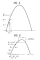
- FIG. 8 An example of the sample data of the error signal is schematically shown in Fig. 8, relating to the second embodiment.
- the sample data inputted to the digital signal processing circuit 14 is normally be inputted in the order Sn-3, Sn-2, Sn-1, Sn.
- the signal Sn is an abnormal signal and thus, the true value Sn can not be obtained, in the conventional method, the value Sn-1 was used as the error signal Sn (shown by ⁇ in Fig. 6).
- a value Sn′ (shown by a in Fig. 6) is sought from the quadratic approximation by using the values Sn-3 ⁇ Sn-1, and this value Sn′ is used as the error signal Sn.
- a key to the present invention is the accuracy of the approximation in a section A shown in Fig. 8. It is considered that an error signal available to quadratic or cubic approximation can be resembled to the true value. If the accuracy of the approximation can not be available, it is possible to improve it by the following method.
- an inclination is sought by the estimated values Sn′ and Sn-1, and, if the inclination is great, the polynominal approximation (in the illustrated embodiment, quadratic approximation) is used, whereas, if the inclination is small, the first previous or prior error signal is used as it is, as in the conventional technique.
- the present invention can be effectively applied to an apparatus which controls the tracking servo control, focus servo control as well as the sample servo control at the time shared mode.
- the digital servo control apparatus if the tracking servo control and the focus servo control are attempted to be effected simultaneously by the use of a single digital signal processing circuit, since it is impossible to perform two servo control simultaneously, the tracking servo control and the focus servo control should be performed alternately.
- the present invention is also useful in such case.
Landscapes
- Optical Recording Or Reproduction (AREA)
Abstract
Description
- The present invention relates to a recording and reproducing apparatus for an optical recording medium, and more specifically, it relates to an optical information recording and reproducing apparatus having a function for correcting the abnormity and/or impossibility of detection of a servo error signal.
- In the past, for example, optical discs have been known as an optical recording medium. The optical disc has concentric or spiral tracks and is divided into a plurality of sectors for permitting the recording of the data having variable lengths and the high speed access. The recording and reproducing of information regarding such optical disc is performed by illuminating a light beam spot emitted from an optical head onto a desired track of the disk while effecting the focusing and tracking servo control.
- The above servo control is generally divided into two groups, i.e., an analogue servo control and a digital servo control, on the basis of the difference of signals to be handled. Recently, an interest has been directed to the digital servo control, since it can provide a stable servo control operation.
- Fig. 1 shows an example of a conventional digital servo control apparatus. In Fig. 1, the
reference numeral 1 denotes an optical disc as a recording medium; 2 denotes an optical system for an optical head; 3 denotes a tracking error detector for detecting a tracking error signal on the basis of an output from theoptical system 2; 4 denotes a focus error detector for detecting a focus error signal on the basis of an output from theoptical system 2. With respect to thetracking error detector 3 and thefocus error detector 4, a known detecting method used in the optical information recording and reproducing apparatus can be adopted. For example, a push-pull method can be adopted to the tracking error detection, and an astigmatism method can be adopted to the focus error detection. Incidentally, the reference numerals and 6 denote A/D converters for A/D converting the error signals outputted from theerror detectors signal processing circuit 14 into analogue signals; and 13 and 15 denote a tracking actuator and a focus actuator, respectively, for driving theoptical system 2 of the optical head to predetermined directions. Next, the operation of the digital servo control apparatus having the above-mentioned arrangement will be explained. - First of all, when it is desired to record or reproduce information with respect to the
optical disk 1 by means of theoptical system 2, theoptical system 2 is servo-controlled by thefocus actuator 13 and thetracking actuator 15. This is achieved by detecting the tracking error signal and the focus error signal on the basis of the reflected light from theoptical disc 1, by calculating the detected signals using predetermined exchange equations by means of the digital signal processing circuit to obtain a desired control amount, and by activating theactuators - The servo control mode can further be divided into a continuous servo control system and a sample servo control system. The former is a system for performing the servo control by detecting the tracking error signal and the focus error signal at all times during the recording and reproducing operation, and the latter is a system for performing the tracking servo control and focus servo control by detecting the tracking error signal and the focus error signal at time shared control with the use of servo bites provided on the fronts of the respective sectors as shown in Figs. 2A - 2C.
- Next, the control with the sample servo control system by using the above-mentioned digital servo control apparatus will be explained.
- Fig. 2A shows an arrangement of wobble pits and clock pits in the servo bite area used in the sample servo control system. The wobble pits serve to detect the tracking error, and the clock pits serve to generate a clock signal for reproducing the data.
- In the servo bite area, when the light beam spot is in an on-track condition, outputs as shown in Fig. 28 can be obtained, as the light beam spot is moved. The tracking error singal is obtained as "0" by A/D converting the outputs and then by calculating them on the basis of the subtraction TA - TB by means of the digital signal processing circuit. If the light beam spot is slightly shifted toward the wobble pit A, as shown in Fig. 2C, the tracking error signal S is obtained by calculating the subtraction TA - TB If the light beam spot passes across the track, the value S of TA - TB will be changed as shown in Fig. 3. The focus error signal is detected at a mirror plane (not shown) provided behind the wobble pits. Thereafter, as is the conventional method, the control amount for the tracking and focus actuators is sought by performing the calculation on the basis of the predetermined exchange equations in the digital signal processing circuit, and the actuators are activated on the basis of the control amount. In this way, the control amount for the tracking and focus actuators obtained each servo bite area is held for a given time until a new control amount is sought in the next servo bite area. And, the control in a certain servo bite area is performed on the basis of the control amount held for said bite area.
- However, in the control system as the above-mentioned sample servo control system, wherein the control is performed by detecting the tracking error signal and the focus error signal at time, shared mode, the following problem arose.
- If during the error detecting operation the tracking error signal or the focus error signal is not obtained due to defect and/or damage of the disc or the presence of the dust, the desired control for the light beam spot can not be effected until the next error signals are obtained.
- In order to solve such problem, conventionally, if the error signal could not be obtained, the servo control was performed by using the error signal obtained just before the occurrence of the impossibility of detection.
- However, with this conventional method, the accurate control is not always obtained; particularly, if the error signal can not be obtained continuously for a long time, the conventional method worsens the control accuracy and can not provide an adequate counter-measure.
- The present invention aims to eliminate the above-mentioned conventional drawbacks, and an object of the present invention is to provide an optical information recording and reproducing apparatus which can perform an accurate servo control for a light beam spot even if an error signal cannot be detected during the error signal detecting operation in a servo control system wherein the servo control is performed by detecting tracking error signal and/or a focus error signal at a time shared mode.
- The above object is achieved by providing an optical information recording and reproducing apparatus in which a light beam spot is properly illuminated onto a recording medium by detecting a tracking error signal and/or a focus error signal at a time shared mode and by activating a tracking actuator and/or a focus actuator, thereby performing the recording and reproducing of information, and wherein means is provided for estimating an error singal on the basis of a plurality of error signals previously detected, when any error signal cannot be detected during the error signal detecting operation.
-
- Fig. 1 is a block diagram showing an example of a conventional digital servo control apparatus;
- Figs. 2A to 2C are views showing a control with a sample servo control system performed by using the digital servo control apparatus of Fig. 1;
- Fig. 3 is a graph showing the change in a value S of TA - TB obtained from Figs. 2A to 2C;
- Fig. 4 is a block diagram showing an example of a construction of an optical information recording and reproducing apparatus according to a first embodiment of the present invention;
- Fig. 5 is a flow chart showing an operation in the servo control by means of the apparatus according to the first embodiment of the present invention of Fig. 4;
- Fig. 6 is a graph showing an example of sample data of an error signal in the apparatus according to the first embodiment;
- Fig. 7 is a flow chart showing an operation in the servo control by means of an optical information recording and reproducing apparatus according to a second embodiment of the present invention; and
- Fig. 8 is a graph showing an example of sample data of an error signal in the apparatus according to the second embodiment.
- Fig. 4 is a block diagram showing an example of a construction of an optical information recording and reproducing apparatus according to the present invention.
- In Fig. 4, the
reference numeral 7 denotes an input/output control unit (hereinafter, referred to as "I/O control unit"), and 9 and 10 denote memories. The reference numeral 8 denotes an external data input device. Incidentally, anoptical system 2,tracking actuator 15,focus actuator 13,tracking error detector 3,focus error detector 4, A/D converters A converters signal processing circuit 14 may be the same as those of the conventional apparatus shown in Fig. 1. - Next, an operation of a servo control apparatus constructed as above will be explained.
- Fig. 5 is a flow chart showing an operation in the servo control performed by means of the apparatus according to a first embodiment of the present invention.
- Hereinafter, the operation of the servo control apparatus during the reproducing operation will be fully explained with reference to Figs. 4 and 5.
- Incidentally, the description is given here with respect to a tracking servo control, but the present invention can be similarly adapted to a focus servo control.
- The reflected light beam spot from the servo bite area of the
optical disc 1 is introduced into theoptical system 2, where a tracking error signal is detected by thetracking error detector 3. The tracking error signal is converted into a digital signal by the A/D converter 5 and then is inputted to the digitalsignal processing circuit 14 through the I/O control unit 7 (step S1). The digitalsignal processing circuit 14 judges whether the error signal is normal or abnormal on the basis of change in level of the signal (step S2). If the signal is abnormal one due to the defect and/or damage of the disc or the presence of the dust, an error signal Sn is sought by adding a first previous data Sn-1 to a difference bS between the second previous data Sn-2 and the first previous date Sn-1 (ΔS = Sn-1 - Sn-2) (step S3). And, a difference ΔS between the obtained Sn and the first previous error signal Sn in the previous servo bite area is sought, and these values Sn and ΔS are temporarily stored in the memory 9 (step S4). Next, the digitalsignal processing circuit 14 seeks an control amount by calculating the value Sn on the basis of a predetermined exchange equation (step S5). The calculated result is outputted to the D/A converter 11 through the I/O control unit 7 (step S6). The control amount is converted into an analogue amount by the D/A converter 11 and is inputted to the trackingactuator 15, thus performing the tracking servo control. The tracking servo control is continued with the control amount until a new control amount is obtained in the next servo bite area. On the other hand, in the step S2, if the signal is judged as a normal one, the digitalsignal processing circuit 14 seeks a difference ΔS between the value Sn and the first previous error signal Sn-1, and these values Sn and ΔS are temporarily stored in thememory 9. - An example of a sample data of the error signal is schematically shown in Fig. 6.
- The sample data inputted to the digital
signal processing circuit 14 is normally be inputted in the order of Sn-2, Sn-1, Sn. As mentioned above, if the signal Sn is an abnormal signal and thus, the true value Sn can not be obtained, in the conventional method, the value Sn-1 was used as the error signal Sn (shown by b in Fig. 6). However, in the present invention, the difference b S = Sn-1 - Sn-2 is sought, and a vlaue Sn′ = Sn-1 + ΔS is used as the error signal Sn (shown by □ in Fig. 6). - As shown in Fig. 6, it can be seen that the value Sn′ of the present invention closely resembles to the true error signal Sn.
- Next, a second embodiment of the present invention will be explained. Fig. 7 is a flow chart showing an operation in the servo control performed by means of an apparatus according to a second embodiment.
- Hereinafter, the operation of the servo control apparatus during the reproducing operation will be fully described in connection with the second embodiment with reference to Fig. 7. Incidentally, the arrangement of the apparatus itself is the same as that of the previous embodiment.
- The reflected light beam spot from the servo bite area of the
optical disc 1 is introduced into theoptical system 2, where a tracking error signal is detected by thetracking error detector 3. The tracking error signal is converted into a digital signal by the A/D converter 5 and then is inputted to the digitalsignal processing circuit 14 through the I/O control unit 7 (step S7). The digitalsignal processing circuit 14 judges whether the error signal is normal or abnormal (step S8). If the signal is the abnormal one due to the defect and/or damage of the disc or the presence of the dust, an error signal Sn is sought from the following equation by using the data stored in the memory 9 (step S9):
Sn = (Sn-3 + Sn-2 + Sn-1)/3 + (Sn-1 - Sn-3)
And, the digitalsignal processing circuit 14 seeks an control amount by calculating the value Sn on the basis of a predetermined exchange equation (step S11). The calculated result is outputted to the D/A converter 11 through the I/O control unit 7 (step S12). The control amount is converted into an analogue amount by the D/A converter 11 and is inputted to the trackingactuator 15, thus performing the tracking servo control. The tracking servo control is continued with the control amount until a new control amount is obtained in the next servo bite area. - On the other hand, in the step S8, if the signal is judged as a normal one, the second previous tracking error signal Sn-2 detected in the previous servo bite area, the first previous tracking error signal Sn-1, and the present tracking error signal Sn are stored in the
memory 9 at a time shared mode, as the third previous or three steps prior tracking error signal Sn-3, second previous or two steps prior tracking error signal Sn-2, and first previous tracking error signal Sn-1, respectively (step S10). - Incidentally, in this second embodiment, while an example that the contents in the
memory 9 are rewritten in order whenever a new tracking error signal Sn is obtained to store the data at the time shared mode was explained, for example, only the latest error signal Sn may be stored in an address next to the address of the just previously stored error signal in thememory 9. - An example of the sample data of the error signal is schematically shown in Fig. 8, relating to the second embodiment.
- The sample data inputted to the digital
signal processing circuit 14 is normally be inputted in the order Sn-3, Sn-2, Sn-1, Sn. As mentioned above, if the signal Sn is an abnormal signal and thus, the true value Sn can not be obtained, in the conventional method, the value Sn-1 was used as the error signal Sn (shown by Δ in Fig. 6). - However, in the present invention, a value Sn′ (shown by a in Fig. 6) is sought from the quadratic approximation by using the values Sn-3 ∼ Sn-1, and this value Sn′ is used as the error signal Sn.
- As shown in Fig. 8, it can be seen that the value Sn′ of the present invention closely resembles to the true error signal Sn.
- Further, if the signal Sn+1 is also judged as an abnormal signal, a value Sn+1′ is similarly sought by using the values Sn-2 ∼ Sn, and the servo control is continued by using this sought value.
- A key to the present invention is the accuracy of the approximation in a section A shown in Fig. 8. It is considered that an error signal available to quadratic or cubic approximation can be resembled to the true value. If the accuracy of the approximation can not be available, it is possible to improve it by the following method.
- In this method, an inclination is sought by the estimated values Sn′ and Sn-1, and, if the inclination is great, the polynominal approximation (in the illustrated embodiment, quadratic approximation) is used, whereas, if the inclination is small, the first previous or prior error signal is used as it is, as in the conventional technique.
- In the illustrated embodiment, while the servo control using the sample servo control was explained, the present invention can be effectively applied to an apparatus which controls the tracking servo control, focus servo control as well as the sample servo control at the time shared mode. For example, in the digital servo control apparatus, if the tracking servo control and the focus servo control are attempted to be effected simultaneously by the use of a single digital signal processing circuit, since it is impossible to perform two servo control simultaneously, the tracking servo control and the focus servo control should be performed alternately. The present invention is also useful in such case.
Claims (5)
means for supposing an error signal on the basis of a plurality of error signals previously detected, when any error signal can not be detected during an error signal detecting operation.
Sn = (Sn-1 - Sn-2) + Sn-1
where, Sn is an error signal to be supposed Sn-1 is an error signal obtained by the prior detection, and Sn-2 is an error signal obtained by two steps prior detection.
Sn = (Sn-3 + Sn-2 + Sn-1)/3 + (Sn-1 - Sn-3)
where, Sn is an error signal to be supposed, Sn-1 is an error signal obtained by the prior detection, Sn-2 is an error signal obtained by the two steps prior detection, and Sn-3 is an error signal obtained by three steps prior detection.
Applications Claiming Priority (4)
| Application Number | Priority Date | Filing Date | Title |
|---|---|---|---|
| JP18358189 | 1989-07-18 | ||
| JP183581/89 | 1989-07-18 | ||
| JP170067/90 | 1990-06-29 | ||
| JP2170067A JPH03130936A (en) | 1989-07-18 | 1990-06-29 | Optical information recording and reproducing device |
Publications (3)
| Publication Number | Publication Date |
|---|---|
| EP0409574A2 true EP0409574A2 (en) | 1991-01-23 |
| EP0409574A3 EP0409574A3 (en) | 1991-11-13 |
| EP0409574B1 EP0409574B1 (en) | 1996-10-23 |
Family
ID=26493187
Family Applications (1)
| Application Number | Title | Priority Date | Filing Date |
|---|---|---|---|
| EP19900307818 Expired - Lifetime EP0409574B1 (en) | 1989-07-18 | 1990-07-17 | Optical information recording and reproducing apparatus |
Country Status (2)
| Country | Link |
|---|---|
| EP (1) | EP0409574B1 (en) |
| DE (1) | DE69028954T2 (en) |
Cited By (4)
| Publication number | Priority date | Publication date | Assignee | Title |
|---|---|---|---|---|
| EP0443847A2 (en) * | 1990-02-22 | 1991-08-28 | Canon Kabushiki Kaisha | Information recording/reproducing apparatus |
| EP0566778A2 (en) * | 1991-11-06 | 1993-10-27 | Sony Corporation | Optical disk player with digital servo-control circuit |
| US5428590A (en) * | 1991-06-04 | 1995-06-27 | Canon Kabushiki Kaisha | Information recording and reproducing apparatus and method in which an information recording or reproducing head seeks a desired track on a recording medium |
| US5646915A (en) * | 1991-05-29 | 1997-07-08 | Canon Kabushiki Kaisha | Information recording/reproducing apparatus in which a control value for controlling a recording/reproducing head is generated on the basis of a corrected current moving velocity and a target moving velocity |
Citations (1)
| Publication number | Priority date | Publication date | Assignee | Title |
|---|---|---|---|---|
| EP0253328A2 (en) * | 1986-07-11 | 1988-01-20 | Hitachi, Ltd. | Light spot position control system and method by sampling servo |
-
1990
- 1990-07-17 EP EP19900307818 patent/EP0409574B1/en not_active Expired - Lifetime
- 1990-07-17 DE DE1990628954 patent/DE69028954T2/en not_active Expired - Fee Related
Patent Citations (1)
| Publication number | Priority date | Publication date | Assignee | Title |
|---|---|---|---|---|
| EP0253328A2 (en) * | 1986-07-11 | 1988-01-20 | Hitachi, Ltd. | Light spot position control system and method by sampling servo |
Cited By (10)
| Publication number | Priority date | Publication date | Assignee | Title |
|---|---|---|---|---|
| EP0443847A2 (en) * | 1990-02-22 | 1991-08-28 | Canon Kabushiki Kaisha | Information recording/reproducing apparatus |
| EP0443847A3 (en) * | 1990-02-22 | 1992-03-18 | Canon Kabushiki Kaisha | Information recording/reproducing apparatus |
| US5475663A (en) * | 1990-02-22 | 1995-12-12 | Canon Kabushiki Kaisha | Information recording/reproducing apparatus |
| US5646915A (en) * | 1991-05-29 | 1997-07-08 | Canon Kabushiki Kaisha | Information recording/reproducing apparatus in which a control value for controlling a recording/reproducing head is generated on the basis of a corrected current moving velocity and a target moving velocity |
| US5428590A (en) * | 1991-06-04 | 1995-06-27 | Canon Kabushiki Kaisha | Information recording and reproducing apparatus and method in which an information recording or reproducing head seeks a desired track on a recording medium |
| EP0566778A2 (en) * | 1991-11-06 | 1993-10-27 | Sony Corporation | Optical disk player with digital servo-control circuit |
| EP0566778A3 (en) * | 1991-11-06 | 1993-12-01 | Sony Corp | Optical disk player with digital servo-control circuit |
| EP0739002A1 (en) * | 1991-11-06 | 1996-10-23 | Sony Corporation | Optical disk player with digital servo-control circuit |
| US5623465A (en) * | 1991-11-06 | 1997-04-22 | Sony Corporation | Optical disk player with a digital servo-control circuit incorporating a time sharing multifunctional digital filter |
| US5682307A (en) * | 1991-11-06 | 1997-10-28 | Sony Corporation | Circuits and methods for controlling a tracking actuator of an optical disk player |
Also Published As
| Publication number | Publication date |
|---|---|
| DE69028954D1 (en) | 1996-11-28 |
| EP0409574B1 (en) | 1996-10-23 |
| DE69028954T2 (en) | 1997-03-06 |
| EP0409574A3 (en) | 1991-11-13 |
Similar Documents
| Publication | Publication Date | Title |
|---|---|---|
| EP0458319B1 (en) | Servo system for optical recording reproducing drive | |
| US5018124A (en) | Information recording method and apparatus for recording information on track positioned at least two tracks ahead when abnormality of tracking servo is detected | |
| US5235576A (en) | Optical disc apparatus | |
| US6160773A (en) | Optical disk device | |
| US5483510A (en) | Optical information recording and reproducing apparatus that approximates an error signal when one cannot be detected | |
| US4872152A (en) | Light spot position control system and method by sampled servo | |
| EP0409574A2 (en) | Optical information recording and reproducing apparatus | |
| JP3110856B2 (en) | Optical head access control device | |
| US5283776A (en) | Track-counting method for use in optical disk apparatus | |
| KR920006123B1 (en) | Magnetic disk operating device and magnetic head position setting method | |
| US5185730A (en) | Method for reading data from optical disk | |
| EP0607045B1 (en) | Information recording and/or reproducing apparatus and information recording and/or reproducing method | |
| JPH0430092B2 (en) | ||
| US5675560A (en) | Information recording/reproducing apparatus with function of seeking light beam to target position, and method therefor | |
| US4989196A (en) | Optical information recording apparatus | |
| EP0390467B1 (en) | Digital servo control apparatus | |
| US5109370A (en) | Information reading device for information recording medium having track structure | |
| EP0403224A2 (en) | Method of reading recorded information from information storage medium with tracks | |
| EP0840298B1 (en) | Reproduction apparatus and methods for recording media | |
| EP0683488B1 (en) | Method of measuring linear velocity of disk | |
| US20050041542A1 (en) | Optical display device | |
| EP1627381B1 (en) | Extended focus control | |
| JP2611731B2 (en) | Track width inspection device | |
| JP3341540B2 (en) | Track direction positioning device | |
| JPH0627028Y2 (en) | Servo device for rotating recording media |
Legal Events
| Date | Code | Title | Description |
|---|---|---|---|
| PUAI | Public reference made under article 153(3) epc to a published international application that has entered the european phase |
Free format text: ORIGINAL CODE: 0009012 |
|
| AK | Designated contracting states |
Kind code of ref document: A2 Designated state(s): DE FR GB IT NL |
|
| 17P | Request for examination filed |
Effective date: 19901231 |
|
| PUAL | Search report despatched |
Free format text: ORIGINAL CODE: 0009013 |
|
| AK | Designated contracting states |
Kind code of ref document: A3 Designated state(s): DE FR GB IT NL |
|
| 17Q | First examination report despatched |
Effective date: 19940211 |
|
| GRAH | Despatch of communication of intention to grant a patent |
Free format text: ORIGINAL CODE: EPIDOS IGRA |
|
| GRAH | Despatch of communication of intention to grant a patent |
Free format text: ORIGINAL CODE: EPIDOS IGRA |
|
| GRAA | (expected) grant |
Free format text: ORIGINAL CODE: 0009210 |
|
| AK | Designated contracting states |
Kind code of ref document: B1 Designated state(s): DE FR GB IT NL |
|
| REF | Corresponds to: |
Ref document number: 69028954 Country of ref document: DE Date of ref document: 19961128 |
|
| ET | Fr: translation filed | ||
| ITF | It: translation for a ep patent filed |
Owner name: SOCIETA' ITALIANA BREVETTI S.P.A. |
|
| PLBE | No opposition filed within time limit |
Free format text: ORIGINAL CODE: 0009261 |
|
| STAA | Information on the status of an ep patent application or granted ep patent |
Free format text: STATUS: NO OPPOSITION FILED WITHIN TIME LIMIT |
|
| 26N | No opposition filed | ||
| REG | Reference to a national code |
Ref country code: GB Ref legal event code: IF02 |
|
| PGFP | Annual fee paid to national office [announced via postgrant information from national office to epo] |
Ref country code: NL Payment date: 20060616 Year of fee payment: 17 |
|
| PGFP | Annual fee paid to national office [announced via postgrant information from national office to epo] |
Ref country code: GB Payment date: 20060717 Year of fee payment: 17 |
|
| PGFP | Annual fee paid to national office [announced via postgrant information from national office to epo] |
Ref country code: FR Payment date: 20060721 Year of fee payment: 17 |
|
| PGFP | Annual fee paid to national office [announced via postgrant information from national office to epo] |
Ref country code: IT Payment date: 20060731 Year of fee payment: 17 |
|
| PGFP | Annual fee paid to national office [announced via postgrant information from national office to epo] |
Ref country code: DE Payment date: 20060918 Year of fee payment: 17 |
|
| GBPC | Gb: european patent ceased through non-payment of renewal fee |
Effective date: 20070717 |
|
| NLV4 | Nl: lapsed or anulled due to non-payment of the annual fee |
Effective date: 20080201 |
|
| PG25 | Lapsed in a contracting state [announced via postgrant information from national office to epo] |
Ref country code: NL Free format text: LAPSE BECAUSE OF NON-PAYMENT OF DUE FEES Effective date: 20080201 Ref country code: DE Free format text: LAPSE BECAUSE OF NON-PAYMENT OF DUE FEES Effective date: 20080201 |
|
| PG25 | Lapsed in a contracting state [announced via postgrant information from national office to epo] |
Ref country code: GB Free format text: LAPSE BECAUSE OF NON-PAYMENT OF DUE FEES Effective date: 20070717 |
|
| REG | Reference to a national code |
Ref country code: FR Ref legal event code: ST Effective date: 20080331 |
|
| PG25 | Lapsed in a contracting state [announced via postgrant information from national office to epo] |
Ref country code: FR Free format text: LAPSE BECAUSE OF NON-PAYMENT OF DUE FEES Effective date: 20070731 |
|
| PG25 | Lapsed in a contracting state [announced via postgrant information from national office to epo] |
Ref country code: IT Free format text: LAPSE BECAUSE OF NON-PAYMENT OF DUE FEES Effective date: 20070717 |