EP0409518A2 - Motorcycle tyre - Google Patents
Motorcycle tyre Download PDFInfo
- Publication number
- EP0409518A2 EP0409518A2 EP90307732A EP90307732A EP0409518A2 EP 0409518 A2 EP0409518 A2 EP 0409518A2 EP 90307732 A EP90307732 A EP 90307732A EP 90307732 A EP90307732 A EP 90307732A EP 0409518 A2 EP0409518 A2 EP 0409518A2
- Authority
- EP
- European Patent Office
- Prior art keywords
- point
- tyre
- carcass
- bead
- section width
- Prior art date
- Legal status (The legal status is an assumption and is not a legal conclusion. Google has not performed a legal analysis and makes no representation as to the accuracy of the status listed.)
- Granted
Links
- 239000011324 bead Substances 0.000 claims abstract description 36
- 229920000728 polyester Polymers 0.000 description 6
- 230000003247 decreasing effect Effects 0.000 description 3
- 230000007423 decrease Effects 0.000 description 2
- 230000008961 swelling Effects 0.000 description 2
- 101150004367 Il4i1 gene Proteins 0.000 description 1
- 239000004677 Nylon Substances 0.000 description 1
- 229920000297 Rayon Polymers 0.000 description 1
- 229910000831 Steel Inorganic materials 0.000 description 1
- 238000005452 bending Methods 0.000 description 1
- 239000000835 fiber Substances 0.000 description 1
- 239000000463 material Substances 0.000 description 1
- 229920001778 nylon Polymers 0.000 description 1
- FFNMBRCFFADNAO-UHFFFAOYSA-N pirenzepine hydrochloride Chemical compound [H+].[H+].[Cl-].[Cl-].C1CN(C)CCN1CC(=O)N1C2=NC=CC=C2NC(=O)C2=CC=CC=C21 FFNMBRCFFADNAO-UHFFFAOYSA-N 0.000 description 1
- 239000002964 rayon Substances 0.000 description 1
- 238000011084 recovery Methods 0.000 description 1
- 239000010959 steel Substances 0.000 description 1
Images

Classifications
-
- B—PERFORMING OPERATIONS; TRANSPORTING
- B60—VEHICLES IN GENERAL
- B60C—VEHICLE TYRES; TYRE INFLATION; TYRE CHANGING; CONNECTING VALVES TO INFLATABLE ELASTIC BODIES IN GENERAL; DEVICES OR ARRANGEMENTS RELATED TO TYRES
- B60C3/00—Tyres characterised by the transverse section
- B60C3/04—Tyres characterised by the transverse section characterised by the relative dimensions of the section, e.g. low profile
-
- B—PERFORMING OPERATIONS; TRANSPORTING
- B60—VEHICLES IN GENERAL
- B60C—VEHICLE TYRES; TYRE INFLATION; TYRE CHANGING; CONNECTING VALVES TO INFLATABLE ELASTIC BODIES IN GENERAL; DEVICES OR ARRANGEMENTS RELATED TO TYRES
- B60C9/00—Reinforcements or ply arrangement of pneumatic tyres
- B60C9/02—Carcasses
- B60C9/0292—Carcass ply curvature
-
- Y—GENERAL TAGGING OF NEW TECHNOLOGICAL DEVELOPMENTS; GENERAL TAGGING OF CROSS-SECTIONAL TECHNOLOGIES SPANNING OVER SEVERAL SECTIONS OF THE IPC; TECHNICAL SUBJECTS COVERED BY FORMER USPC CROSS-REFERENCE ART COLLECTIONS [XRACs] AND DIGESTS
- Y10—TECHNICAL SUBJECTS COVERED BY FORMER USPC
- Y10T—TECHNICAL SUBJECTS COVERED BY FORMER US CLASSIFICATION
- Y10T152/00—Resilient tires and wheels
- Y10T152/10—Tires, resilient
- Y10T152/10495—Pneumatic tire or inner tube
- Y10T152/10819—Characterized by the structure of the bead portion of the tire
-
- Y—GENERAL TAGGING OF NEW TECHNOLOGICAL DEVELOPMENTS; GENERAL TAGGING OF CROSS-SECTIONAL TECHNOLOGIES SPANNING OVER SEVERAL SECTIONS OF THE IPC; TECHNICAL SUBJECTS COVERED BY FORMER USPC CROSS-REFERENCE ART COLLECTIONS [XRACs] AND DIGESTS
- Y10—TECHNICAL SUBJECTS COVERED BY FORMER USPC
- Y10T—TECHNICAL SUBJECTS COVERED BY FORMER US CLASSIFICATION
- Y10T152/00—Resilient tires and wheels
- Y10T152/10—Tires, resilient
- Y10T152/10495—Pneumatic tire or inner tube
- Y10T152/10855—Characterized by the carcass, carcass material, or physical arrangement of the carcass materials
Definitions
- the present invention relates to a pneumatic tyre for motorcycles, in which running stability under low pressure service conditions is improved.
- Such a conventional motor cycle tyre is shown in Fig.2 where the carcass has a round profile under the low pressure conditions, which shape is almost the same as that for ordinary use on the road at a higher pressure (normal pressure). Therefore, when loaded, the sidewall portions m are deformed such that the whole of the sidewall portion m is curved outwards of the tyre in an arc. However, the deformation is liable to occur unstably and alternatively on the sidewall portions, which greatly deteriorates running stability.
- the suppleness of the tread portion is apt to be lost.
- the deformation occurs all over the tyre as mentioned above, and accordingly it takes a long time to recover from the deformed state to its normal state since the air pressure is low, which also deteriorates running stability.
- an object of the present invention to provide a low pressure motorcycle tyre in which running stability is improved by arranging specially the tyre shape.
- a low pressure motor cycle tyre has a pair of bead portions, a tread portion, and a pair of sidewall portions, and the tyre comprises a bead core disposed in each bead portion, and a carcass extending between the bead portions and secured to the bead cores characterised in that the ratio (A/B) of the tyre section width (A) to the bead width (B) when the tyre is mounted on its regular rim and inflated to 15% of the maximum pressure is not less than 1.90 and not more than 2.20 where the tyre section width (A) is measured at the same radial height as the carcass maximum section width point (p) in the tyre sidewall portions at which the section width of the carcass is maximum.
- the A/B ratio is more than 2.20, the amount of swelling is excessive and the vertical stiffness has a tendency to decrease, and further, tyre performance at normal pressure such as wear resistance and cut resistance of the tread are sacrificed.
- the A/B ratio is less than 1.90, the lateral stiffness is decreased and running stability is lost.
- a middle portion (C) of the carcass profile defined between a point (W1) and a point (W2) is formed by an arc (Sc) having a curvature of a single radius (Rc) and having a centre (o1) inside the tyre;
- the point (W1) is located radially outside the above mentioned carcass maximum section width point (p);
- the point (W2) is located radially inside the carcass maximum section width point (p);
- the radial distance (L2) between the points (W2) and (p) is more than 1.0 times and not more than 1.2 time the radial distance (11) between the points (W1) and (P);
- the radial distance (L) between the points (W1) and (W2) is not less than 0.4 times and not more than 0.6 times the radial height (H) of the carcass measured from the bead base (b) to a point (a) on the tyre equator; and the radial distance (L3) measured from
- the curved middle portions of the carcass induce stable bending deformation in the sidewall portions and restrict the deformation to a narrow region so that the recovery time is shortened. Further, the middle portions help increase the vertical stiffness of the tyre under both low pressure and normal pressure operation.
- a radially inner portion (U) of the carcass profile defined as the portion extending from the radially inner point (W2) to the bead base region, is preferably formed by an arc (Su) having a centre (o2) outside the tyre and having a curvature of a single radius (Ru) smoothly connected to the above mentioned arc (Sc) of the middle portion (C) at the point (W2) as a point of inflection therebetween. Therefore, the inner portion of the carcass promotes the occurrence of the above mentioned stable deformation of the sidewall and increases the lateral stiffness of the tyre.
- a low pressure motorcycle tyre 1 according to the present invention is 4.00R18 4PR in size, and is shown mounted on a regular rim 9 of size 2.15x18 and inflated to 15% of the maximum pressure.
- the maximum air pressure for this tyre size is 2.25 kgf/sg.cm. the carcass profile at the 15% pressure is different from the fully inflated profile but is almost the same as the moulded profile of the tyre.
- the tyre 1 has a tread portion 5, a pair of bead portions 3 and sidewalls.
- Each bead includes a bead core 2 and a carcass 6 extending between the bead portions 3 through the sidewalls 4 and the tread portions 5.
- the rim 9 is a drop centre rim having a tyre mounting well in the centre thereof, and a pair of bead seats 21 for the tyre bead portions 3 are formed one on each side of the, and from the axially outer edge of each bead seat a rim flange 7 extends radially outwardly along the outside of the tyre bead portion 3.
- the carcass 6 comprises at least one ply 23 of cords laid at an angle of 30 to 90 degrees to the tyre equator CO and turned up around the bead cores 2 from the axially inside to the outside thereof to be secured thereto.
- organic fibre cords such as nylon, polyester, rayon and the like are preferably used, but steel cords may be used.
- the carcass 6 is composed of two radial plies 23 in which the cords are laid at about 80 degrees to the tyre equator in the same direction in each ply but in opposite directions with respect to the tyre equator between the adjacent plies.
- the tread portion 5 is provided with no belt structure so as not to increase the rigidity of the tread portion.
- the tyre 1 in this embodiment is a beltless radial tyre.
- the ratio A/B of the maximum tyre section width A when the tyre is mounted on the regular rim 9 and inflated to 15% of the maximum pressure, to the bead width must be set to be not less than 1.90 and not more than 2.20.
- the maximum tyre section width A is measured in the tyre sidewall region at the same radial height as the maximum carcass section width point p at which the carcass section width is maximum and the bead width B is corresponding to the rim 9 measured between the rim flanges 7.
- the carcass shape or profile when the tyre is mounted on the regular rim 9 and inflated to 15% of the maximum pressure is arranged as follows: a middle portion (C) of the carcass profile defined between a radially outward point (W1) and an inward point (W2) is formed by an arc (Sc), where the outward point (W1) is located radially outside the above mentioned carcass maximum section width point (p), and the inward point (W2) is located inside the carcass maximum section width point (p); the arc (Sc) has a curvature of a single radius (Rc) and the centre (o1) thereof is positioned inside the tyre and radially outward of the carcass maximum section width point (p) and further on the same side of the tyre equator (CO); the radial distance (L2) between the inward point (W2) and the carcass maximum section width point (p) is set in the range of from 1.0 to 1.2 times the radial distance (L1) between
- a radially inner portion (U) of the above mentioned carcass profile extending from the inward point (W2) to the bead base region is formed by an arc (Us) having a centre (o2) which is positioned outside the tyre and radially inward of the bead base (d).
- the arc (Su) has a curvature of a single radius (Ru) and the arc is smoothly connected to the above mentioned arc (Sc) of the middle portion (C) at the inward point (W2) as a point of inflection, and the radius (Ru) is not larger than the radius (Rc).
- Test tyres of size 4.00R18 4PR including working example tyres (Ex.1 & 2) and reference tyres (Ref.1 & 2) each having the structure shown in Fig.1 but partly modified in size and reference tyre 3 according to the prior art shown in Fig.2 were made to allow comparison tests to be considered.
- the vertical spring coefficients and lateral spring coefficient s were measured for each tyre and further in order to evaluate the running stability of each tyre, tests by a skilled test driver were made.
- test results together with the specifications of the test tyres, are given Table 1.
- Table 1 the test results and the spring coefficients are indicated by an index based on the assumption that the reference tyre 3 is 100, where the larger index is better.
- the carcass profile which at low pressure is similar to the moulded profile is formed in this specific shade to reduce the difference from the loaded shape. Therefore, the amount of sidewall deformation when loaded under low pressure conditions is decreased in both the vertical and lateral directions, and as a result, the vertical and lateral stiffnesses of the tyre as improved while keeping suppleness in the tread portion.
Landscapes
- Engineering & Computer Science (AREA)
- Mechanical Engineering (AREA)
- Tires In General (AREA)
Abstract
Description
- The present invention relates to a pneumatic tyre for motorcycles, in which running stability under low pressure service conditions is improved.
- In general, when running off the road, motorcycle tyres designed for use both on the road and off the road, are inflated to a lower air pressure than the normal road use air pressure, for example 0.5 to 0.25 kgf/sg.cm (which is about 10 to 20% of the road use air pressure). Thus the stiffness of the tread portion is reduced, and the contact area of the tread surface with the ground is increased, and as a result a large ground gripping force is obtained.
- However, in a conventional motor cycle tyre decreasing the air pressure in this way decreases the stiffness of the tyre in the sidewall portions as well as in the tread portion, and as a result running stability is lost under such low pressure service conditions.
- Such a conventional motor cycle tyre is shown in Fig.2 where the carcass has a round profile under the low pressure conditions, which shape is almost the same as that for ordinary use on the road at a higher pressure (normal pressure). Therefore, when loaded, the sidewall portions m are deformed such that the whole of the sidewall portion m is curved outwards of the tyre in an arc. However, the deformation is liable to occur unstably and alternatively on the sidewall portions, which greatly deteriorates running stability.
- Further, as the deformation of the sidewall portions flattens the tread portion n, the suppleness of the tread portion is apt to be lost.
- Furthermore, the deformation occurs all over the tyre as mentioned above, and accordingly it takes a long time to recover from the deformed state to its normal state since the air pressure is low, which also deteriorates running stability.
- It is therefore, an object of the present invention to provide a low pressure motorcycle tyre in which running stability is improved by arranging specially the tyre shape.
- According to one aspect of the present invention, a low pressure motor cycle tyre has a pair of bead portions, a tread portion, and a pair of sidewall portions, and the tyre comprises a bead core disposed in each bead portion, and a carcass extending between the bead portions and secured to the bead cores characterised in that the ratio (A/B) of the tyre section width (A) to the bead width (B) when the tyre is mounted on its regular rim and inflated to 15% of the maximum pressure is not less than 1.90 and not more than 2.20 where the tyre section width (A) is measured at the same radial height as the carcass maximum section width point (p) in the tyre sidewall portions at which the section width of the carcass is maximum.
- As a result axially outward swelling of the sidewall portions is increased more than in a conventional tyre sidewall, and the sidewall shape under low pressure conditions becomes similar to its loaded shape, that is, the difference between the loaded shape and free shape become small. Thus deformation occurs with more stability in both the sidewall portions, and the amount of deformation is less. As a result, running stability is improved while maintaining the tyre stiffness in both the vertical and lateral directions.
- However, if the A/B ratio is more than 2.20, the amount of swelling is excessive and the vertical stiffness has a tendency to decrease, and further, tyre performance at normal pressure such as wear resistance and cut resistance of the tread are sacrificed. On the other hand, when the A/B ratio is less than 1.90, the lateral stiffness is decreased and running stability is lost.
- Further the carcass profile is preferably arranged as follows:
a middle portion (C) of the carcass profile defined between a point (W1) and a point (W2) is formed by an arc (Sc) having a curvature of a single radius (Rc) and having a centre (o1) inside the tyre;
the point (W1) is located radially outside the above mentioned carcass maximum section width point (p);
the point (W2) is located radially inside the carcass maximum section width point (p);
the radial distance (L2) between the points (W2) and (p) is more than 1.0 times and not more than 1.2 time the radial distance (11) between the points (W1) and (P);
the radial distance (L) between the points (W1) and (W2) is not less than 0.4 times and not more than 0.6 times the radial height (H) of the carcass measured from the bead base (b) to a point (a) on the tyre equator; and
the radial distance (L3) measured from the bead base (b) to the above mentioned radially inner point (W2) is not less than 0.15 and not more than 0.35 times the above mentioned radial height (H) of the carcass. - Accordingly, the curved middle portions of the carcass induce stable bending deformation in the sidewall portions and restrict the deformation to a narrow region so that the recovery time is shortened. Further, the middle portions help increase the vertical stiffness of the tyre under both low pressure and normal pressure operation.
- Furthermore, a radially inner portion (U) of the carcass profile, defined as the portion extending from the radially inner point (W2) to the bead base region, is preferably formed by an arc (Su) having a centre (o2) outside the tyre and having a curvature of a single radius (Ru) smoothly connected to the above mentioned arc (Sc) of the middle portion (C) at the point (W2) as a point of inflection therebetween. Therefore, the inner portion of the carcass promotes the occurrence of the above mentioned stable deformation of the sidewall and increases the lateral stiffness of the tyre.
- An embodiment of the present invention will now be described, by way of example only, with reference to the drawings, in which:
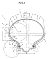
- Fig. 1. is a cross sectional view showing an embodiment of the present invention, and
- Fig. 2. is a cross sectional view showing a conventional tyre.
- In Fig1. a low pressure motorcycle tyre 1 according to the present invention is 4.00R18 4PR in size, and is shown mounted on a
regular rim 9 of size 2.15x18 and inflated to 15% of the maximum pressure. The maximum air pressure for this tyre size is 2.25 kgf/sg.cm. the carcass profile at the 15% pressure is different from the fully inflated profile but is almost the same as the moulded profile of the tyre. - The tyre 1 has a
tread portion 5, a pair ofbead portions 3 and sidewalls. Each bead includes abead core 2 and acarcass 6 extending between thebead portions 3 through the sidewalls 4 and thetread portions 5. - The
rim 9 is a drop centre rim having a tyre mounting well in the centre thereof, and a pair ofbead seats 21 for thetyre bead portions 3 are formed one on each side of the, and from the axially outer edge of each bead seat arim flange 7 extends radially outwardly along the outside of thetyre bead portion 3. - The
carcass 6 comprises at least oneply 23 of cords laid at an angle of 30 to 90 degrees to the tyre equator CO and turned up around thebead cores 2 from the axially inside to the outside thereof to be secured thereto. - For the carcass ply cord, organic fibre cords such as nylon, polyester, rayon and the like are preferably used, but steel cords may be used.
- In this example, the
carcass 6 is composed of tworadial plies 23 in which the cords are laid at about 80 degrees to the tyre equator in the same direction in each ply but in opposite directions with respect to the tyre equator between the adjacent plies. - Further, the
tread portion 5 is provided with no belt structure so as not to increase the rigidity of the tread portion. - Thus, the tyre 1 in this embodiment is a beltless radial tyre.
- According to the present invention, the ratio A/B of the maximum tyre section width A when the tyre is mounted on the
regular rim 9 and inflated to 15% of the maximum pressure, to the bead width must be set to be not less than 1.90 and not more than 2.20. - Here, the maximum tyre section width A is measured in the tyre sidewall region at the same radial height as the maximum carcass section width point p at which the carcass section width is maximum and the bead width B is corresponding to the
rim 9 measured between therim flanges 7. - Further, in this embodiment, the carcass shape or profile when the tyre is mounted on the
regular rim 9 and inflated to 15% of the maximum pressure, is arranged as follows:
a middle portion (C) of the carcass profile defined between a radially outward point (W1) and an inward point (W2) is formed by an arc (Sc), where
the outward point (W1) is located radially outside the above mentioned carcass maximum section width point (p), and the inward point (W2) is located inside the carcass maximum section width point (p);
the arc (Sc) has a curvature of a single radius (Rc) and the centre (o1) thereof is positioned inside the tyre and radially outward of the carcass maximum section width point (p) and further on the same side of the tyre equator (CO);
the radial distance (L2) between the inward point (W2) and the carcass maximum section width point (p) is set in the range of from 1.0 to 1.2 times the radial distance (L1) between the outward point (W1) and the point (p);
the radial distance (L) between the outward and inward points (W1) and (W2) is set in the range of from 0.4 to 0.6 times the radial height (H) of the carcass measured from the bead base (b) to a point (a) on the tyre equator; and
the radial distance (L3) measured from the bead base (0) to the inward point (W2) is set in the range of from 0.15 to 0.35 times the above mentioned radial height (H) of the carcass. - Furthermore, a radially inner portion (U) of the above mentioned carcass profile extending from the inward point (W2) to the bead base region is formed by an arc (Us) having a centre (o2) which is positioned outside the tyre and radially inward of the bead base (d).
- The arc (Su) has a curvature of a single radius (Ru) and the arc is smoothly connected to the above mentioned arc (Sc) of the middle portion (C) at the inward point (W2) as a point of inflection, and the radius (Ru) is not larger than the radius (Rc).
- Test tyres of size 4.00R18 4PR including working example tyres (Ex.1 & 2) and reference tyres (Ref.1 & 2) each having the structure shown in Fig.1 but partly modified in size and
reference tyre 3 according to the prior art shown in Fig.2 were made to allow comparison tests to be considered. The vertical spring coefficients and lateral spring coefficient s were measured for each tyre and further in order to evaluate the running stability of each tyre, tests by a skilled test driver were made. - The test results, together with the specifications of the test tyres, are given Table 1. In Table 1, the test results and the spring coefficients are indicated by an index based on the assumption that the
reference tyre 3 is 100, where the larger index is better. - As described above, in a motorcycle tyre according to the present invention, the carcass profile which at low pressure is similar to the moulded profile is formed in this specific shade to reduce the difference from the loaded shape. Therefore, the amount of sidewall deformation when loaded under low pressure conditions is decreased in both the vertical and lateral directions, and as a result, the vertical and lateral stiffnesses of the tyre as improved while keeping suppleness in the tread portion.
TABE 1 Tire Ex.1 Ex.2 Ref.1 Ref.2 Ref.3 TEST RESULTS ** Running stability (110)* 120 120 110 108 100 Vertical Spring Coefficient (120)* 120 122 108 110 100 Lateral Spring Coefficient (105)* 110 108 103 103 100 Section width A (mm) 121 105 100 127 102 Bead width B (mm) 55 55 55 55 82 Ratio A/B 2.20 1.9 1.8 2.3 1.24 Carcass 2 plies 2 plies 2 plies 2 plies 2 plies Cord material Polyester Polyester Polyester Polyester Polyester 1000d/2 1000d/2 1000d/2 1000d/2 1000d/2 Cord angle (deg) 78 78 78 78 78 Height H (mm) 88 88 88 88 97 Distance L1 (mm) 18 18 18 18 L2 (mm) 22 18 23 22 L3 (mm) 23 21 22 23 L=L1+L2 (mm) 40 36 41 40 Ratio L/H 0.46 0.41 0.47 0.46 L3/H 0.26 0.24 0.25 0.26 Radius Rc (mm) 27 27 27 27 Ru (mm) 27 20 25 25 Belt non non non non non Tire thickness (mm) *** l1 tread center 18.0 18.0 18.0 18.0 18.0 l2 tread shoulder 19.5 19.5 19.5 19.5 19.5 l3 tread edge 20.0 20.0 20.0 20.0 20.0 l4 7.0 7.0 7.0 7.0 7.0 l5 max. width point 5.0 5.0 5.0 5.0 5.0 l6 7.5 7.5 7.5 7.5 7.5 l7 bead base 7.5 7.5 7.5 7.5 7.5 * The numbers in parentheses show the standards. ** Air pressure: 0.3 Kg.sq.cm *** References, l1-l7 correspond to those in Figs.1 & 2.
Claims (3)
Applications Claiming Priority (2)
| Application Number | Priority Date | Filing Date | Title |
|---|---|---|---|
| JP189231/89 | 1989-07-20 | ||
| JP1189231A JPH0354002A (en) | 1989-07-20 | 1989-07-20 | Low internal pressure tire for motorcycle |
Publications (3)
| Publication Number | Publication Date |
|---|---|
| EP0409518A2 true EP0409518A2 (en) | 1991-01-23 |
| EP0409518A3 EP0409518A3 (en) | 1991-07-10 |
| EP0409518B1 EP0409518B1 (en) | 1994-03-30 |
Family
ID=16237791
Family Applications (1)
| Application Number | Title | Priority Date | Filing Date |
|---|---|---|---|
| EP90307732A Expired - Lifetime EP0409518B1 (en) | 1989-07-20 | 1990-07-16 | Motorcycle tyre |
Country Status (3)
| Country | Link |
|---|---|
| US (1) | US5129973A (en) |
| EP (1) | EP0409518B1 (en) |
| JP (1) | JPH0354002A (en) |
Cited By (2)
| Publication number | Priority date | Publication date | Assignee | Title |
|---|---|---|---|---|
| WO1995003945A1 (en) * | 1993-07-30 | 1995-02-09 | Continental Aktiengesellschaft | Vehicle tyre |
| EP3357715A1 (en) * | 2017-02-06 | 2018-08-08 | Sumitomo Rubber Industries, Ltd. | Pneumatic tire |
Families Citing this family (9)
| Publication number | Priority date | Publication date | Assignee | Title |
|---|---|---|---|---|
| JPH0516609A (en) * | 1991-07-12 | 1993-01-26 | Sumitomo Rubber Ind Ltd | Radial tires for motorcycles |
| JP3227402B2 (en) * | 1997-03-07 | 2001-11-12 | 住友ゴム工業株式会社 | Motorcycle tire, method of manufacturing the same, and vulcanizing mold used for the manufacture |
| GB2348481A (en) * | 1999-03-27 | 2000-10-04 | Chart Marston Limited | Heat exchanger and/or fluid mixing means with perforated plates |
| JP4705284B2 (en) * | 2001-09-07 | 2011-06-22 | 住友ゴム工業株式会社 | Radial tire for ATV |
| US7862633B2 (en) * | 2007-04-13 | 2011-01-04 | Battelle Memorial Institute | Method and system for introducing fuel oil into a steam reformer with reduced carbon deposition |
| JP6607045B2 (en) * | 2016-01-07 | 2019-11-20 | 住友ゴム工業株式会社 | Pneumatic tire |
| JP6672892B2 (en) * | 2016-03-03 | 2020-03-25 | 住友ゴム工業株式会社 | Pneumatic tire |
| KR101909682B1 (en) * | 2018-05-14 | 2018-10-18 | 이영기 | Tire structure and combining structure thereof |
| US10780747B2 (en) * | 2018-05-14 | 2020-09-22 | Young Gi Lee | Tire structure and combining structure thereof |
Family Cites Families (9)
| Publication number | Priority date | Publication date | Assignee | Title |
|---|---|---|---|---|
| GB1438288A (en) * | 1972-09-01 | 1976-06-03 | ||
| JPS506681A (en) * | 1973-05-21 | 1975-01-23 | ||
| FR2440278A2 (en) * | 1978-09-28 | 1980-05-30 | Gazuit Georges | ISOSTABLE TIRE |
| JPS55110605A (en) * | 1979-02-19 | 1980-08-26 | Bridgestone Corp | Pneumatic bicycle tire having good high-speed stability |
| JPS58145508A (en) * | 1981-10-07 | 1983-08-30 | Sumitomo Rubber Ind Ltd | Tire-rim assembly for motorcycle |
| JPS58185304A (en) * | 1982-04-23 | 1983-10-29 | Bridgestone Corp | Pneumatic tire for motorcycle |
| JPS62128804A (en) * | 1985-11-30 | 1987-06-11 | Sumitomo Rubber Ind Ltd | Tire for all-ground vehicle |
| JP2554499B2 (en) * | 1987-07-06 | 1996-11-13 | 住友ゴム工業 株式会社 | Flat radial tires |
| JP2574816B2 (en) * | 1987-10-27 | 1997-01-22 | 住友ゴム工業 株式会社 | Safety tire |
-
1989
- 1989-07-20 JP JP1189231A patent/JPH0354002A/en active Pending
-
1990
- 1990-07-13 US US07/552,094 patent/US5129973A/en not_active Expired - Fee Related
- 1990-07-16 EP EP90307732A patent/EP0409518B1/en not_active Expired - Lifetime
Cited By (2)
| Publication number | Priority date | Publication date | Assignee | Title |
|---|---|---|---|---|
| WO1995003945A1 (en) * | 1993-07-30 | 1995-02-09 | Continental Aktiengesellschaft | Vehicle tyre |
| EP3357715A1 (en) * | 2017-02-06 | 2018-08-08 | Sumitomo Rubber Industries, Ltd. | Pneumatic tire |
Also Published As
| Publication number | Publication date |
|---|---|
| JPH0354002A (en) | 1991-03-08 |
| EP0409518A3 (en) | 1991-07-10 |
| EP0409518B1 (en) | 1994-03-30 |
| US5129973A (en) | 1992-07-14 |
Similar Documents
| Publication | Publication Date | Title |
|---|---|---|
| EP0638445B1 (en) | Pneumatic radial tyre | |
| EP0371755B1 (en) | Pneumatic safety tyre | |
| EP1481822B1 (en) | Pneumatic radial tire | |
| EP1428691B1 (en) | Self-supporting pneumatic tire with several innerliners | |
| EP0314445A2 (en) | Safety tyre | |
| EP0346106A1 (en) | Pneumatic tyre | |
| EP0850788B1 (en) | Pneumatic radial tyre | |
| EP0298673A2 (en) | Radial tyre | |
| US6478064B1 (en) | Heavy duty radial tire with chafer height greater than bead apex height | |
| US5435370A (en) | Pneumatic tire having discontinuous outer carcass ply | |
| EP1201464B1 (en) | Pneumatic radial tires | |
| EP1683654B1 (en) | Runflat tire | |
| EP0736400A1 (en) | Heavy duty pneumatic radial tires | |
| EP0635383B1 (en) | Pneumatic tire | |
| EP0409518A2 (en) | Motorcycle tyre | |
| EP0368553A2 (en) | Motorcycle tyre | |
| EP1580038B1 (en) | Run-flat tire | |
| EP0297889A2 (en) | Pneumatic tyre | |
| EP1930186B1 (en) | Runflat tire | |
| EP0321730B1 (en) | Low profile radial tyre | |
| EP0413574A2 (en) | High speed radial tyre | |
| JP2002002216A (en) | Pneumatic tire | |
| EP1580036B1 (en) | Pneumatic tire | |
| EP0755811A2 (en) | Pneumatic tire for two-wheeled vehicle | |
| US5151139A (en) | Heavy duty radial tire having durable buttress portion |
Legal Events
| Date | Code | Title | Description |
|---|---|---|---|
| PUAI | Public reference made under article 153(3) epc to a published international application that has entered the european phase |
Free format text: ORIGINAL CODE: 0009012 |
|
| AK | Designated contracting states |
Kind code of ref document: A2 Designated state(s): FR GB IT |
|
| 17P | Request for examination filed |
Effective date: 19901221 |
|
| PUAL | Search report despatched |
Free format text: ORIGINAL CODE: 0009013 |
|
| AK | Designated contracting states |
Kind code of ref document: A3 Designated state(s): FR GB IT |
|
| 17Q | First examination report despatched |
Effective date: 19930818 |
|
| GRAA | (expected) grant |
Free format text: ORIGINAL CODE: 0009210 |
|
| AK | Designated contracting states |
Kind code of ref document: B1 Designated state(s): FR GB IT |
|
| ITF | It: translation for a ep patent filed | ||
| ET | Fr: translation filed | ||
| PLBE | No opposition filed within time limit |
Free format text: ORIGINAL CODE: 0009261 |
|
| STAA | Information on the status of an ep patent application or granted ep patent |
Free format text: STATUS: NO OPPOSITION FILED WITHIN TIME LIMIT |
|
| 26N | No opposition filed | ||
| PGFP | Annual fee paid to national office [announced via postgrant information from national office to epo] |
Ref country code: FR Payment date: 19990709 Year of fee payment: 10 |
|
| PGFP | Annual fee paid to national office [announced via postgrant information from national office to epo] |
Ref country code: GB Payment date: 19990714 Year of fee payment: 10 |
|
| PG25 | Lapsed in a contracting state [announced via postgrant information from national office to epo] |
Ref country code: GB Free format text: LAPSE BECAUSE OF NON-PAYMENT OF DUE FEES Effective date: 20000716 |
|
| GBPC | Gb: european patent ceased through non-payment of renewal fee |
Effective date: 20000716 |
|
| PG25 | Lapsed in a contracting state [announced via postgrant information from national office to epo] |
Ref country code: FR Free format text: LAPSE BECAUSE OF NON-PAYMENT OF DUE FEES Effective date: 20010330 |
|
| REG | Reference to a national code |
Ref country code: FR Ref legal event code: ST |
|
| PG25 | Lapsed in a contracting state [announced via postgrant information from national office to epo] |
Ref country code: IT Free format text: LAPSE BECAUSE OF NON-PAYMENT OF DUE FEES Effective date: 20050716 |