EP0409498A2 - Pulverizer having rotatable grinding table with replaceable air port segments - Google Patents
Pulverizer having rotatable grinding table with replaceable air port segments Download PDFInfo
- Publication number
- EP0409498A2 EP0409498A2 EP90307681A EP90307681A EP0409498A2 EP 0409498 A2 EP0409498 A2 EP 0409498A2 EP 90307681 A EP90307681 A EP 90307681A EP 90307681 A EP90307681 A EP 90307681A EP 0409498 A2 EP0409498 A2 EP 0409498A2
- Authority
- EP
- European Patent Office
- Prior art keywords
- ring
- grinding table
- segments
- pulverizer
- segmented
- Prior art date
- Legal status (The legal status is an assumption and is not a legal conclusion. Google has not performed a legal analysis and makes no representation as to the accuracy of the status listed.)
- Granted
Links
Images


Classifications
-
- B—PERFORMING OPERATIONS; TRANSPORTING
- B02—CRUSHING, PULVERISING, OR DISINTEGRATING; PREPARATORY TREATMENT OF GRAIN FOR MILLING
- B02C—CRUSHING, PULVERISING, OR DISINTEGRATING IN GENERAL; MILLING GRAIN
- B02C15/00—Disintegrating by milling members in the form of rollers or balls co-operating with rings or discs
- B02C15/001—Air flow directing means positioned on the periphery of the horizontally rotating milling surface
Definitions
- This invention pertains to pulverizers of the roll and race type which have a rotatable grinding table containing air port flow passages. It pertains particularly to such pulverizers for coal having a grinding table with multiple replaceable air port segments provided at the table periphery adajcent an outer segmented ring.
- Pulverizers for coal having a centrally located coal feed conduit and a rotary grinding table and rolls provided in the pulverizer lower portion for pulverizing coal and pneumatically conveying it upwardly to boilers for combustion therein are well known.
- such pulverizers for coal are disclosed by U.S. Patent No.4,264,041 to Kitto, Jr. et al and U.S. 4,687,145 to Dougan et al.
- the carrier air passes upwardly from a plenum through air ports containing a plurality of vanes and entrains pulverized coal upwardly from the outer edge of the rotatable grinding ring.
- This invention provides an improved pulverizer containing a rotatable grinding table having an improved air port configuration, for passing primary air to pulverized material and pneumatically conveying the material such as coal upwardly to a boiler for combustion therein.
- the air port unit is attached rigidly to the grinding table outer periphery, and includes multiple removable ring segments.
- Each ring segment of the air port unit consists of a lower part and an upper part, with each part being removably attached to the outer periphery of the grinding table.
- the ring segments each have air flow passageways provided therein, which are each angled radially inwardly by an angle of 10-20° relative to a vertical plane.
- the flow passages are also each angled forwardly relative to the grinding table direction of rotation at an angle of 40-60° and preferably at about 45° angle with the horizontal plane.
- the use of a 40-60° forward angle as compared to a smaller angle of about 30° results in less direct impingement of the entrained coal stream against the housing, which reduces housing erosion.
- a stationary outer segmented ring is rigidly attached to the inner wall of the pulverizer housing, with a radial gap of 0.100 - 0.190 inches preferably about 0.125 inches being provided between the outer ring wall and the air port rotatable inner ring segments.
- the outer ring includes multiple segments, with each segment having a lower part rigidly attached to the housing wall as by welding, and an upper part removably attached to the outer ring segment lower part such as by bolting.
- air port ring multiple segments having replaceable lower and upper parts provides an improved means for matching of the pulverized air port air flow requirements to a particular pulverizer installation.
- this configuration permits the air port lower segments to be sized to accommodate the larged volumetric air flow for a given pulverizer housing size, and permits the segments upper parts to be sized to provide a desired smaller air flow rate as required to attain the proper air velocity for upward coal transport desired for the particular pulverizer installation.
- the air port ring segment upper parts openings have flow passages which have betwee about 50-100% of the cross-sectional area of the ring segment lower parts.
- This invention advtangeously provides a pulverizer having an air port unit for which the ring segments upper parts, which receive the most erosion wear, can be replaced easily and economically without requiring replacement of the entire air port assembly.
- the air port configuration also advantageously provides for changes in air flow requirements as needed to meet changes in pulverizer operations.
- a coal pulverizer assembly 10 includes an outer casing 12 which encloses a rotary grinding table 14.
- the grinding table 14 is usually supported by rollers in a stationary base structure 16, and is rotatable by a pulverizer gear reducer and drive motor 18 within the base 16.
- Triple equally spaced rollers 20 are pivotably attached to the housing 12 above the rotary grinding table 14. Rollers 20 can each rotate about their own shafts 21 which are pivoted at 22 to housing 12, so that the rollers 20 are each rotated in race 15 and on the coal therein by the rotation of the grinding table 14.
- the coal feed enters the pulverizer via a central downcomer unit 24 and falls onto a central portion 14a of the rotatable grinding table 14.
- the three rotatable grinding roller units 20, which each rest on the grinding table race 15 and the coal therein, progressively crushes the coal particles as they are passed radially outwardly across the grinding table 14 towards a plurality of air ports 30 attached to the periphery of the table 14. Air provided from inlet conduit 26 and plenum 27 flows uniformly upwardly through air ports 30 to carry the pulverized coal particles upwardly to the pulverizer classifier vanes 28 and upper exits 29 to a combustion zone.
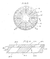
- FIG. 2 A plan view of the pulverizer rotatable grinding table 14 and multiple air ports 30 is shown by Fig. 2. It is seen that the multiple peripheral air ports 30 are provided by a segmented ring 32, which is rigidly attached to the periphery of the grinding table 14. The multiple air ports 30 are provided circumferentially spaced apart in the segmented ring 32, which is removably attached to the periphery of grinding table 14 such as by bolting.
- the segmented ring 32 contains multiple segments 31, with at least 8 arcuate segments and usually not exceeding 20 segments being provided.
- each ring segment 31 consists of an upper piece 31a and a lower piece 31b.
- a multi-piece segmented retainer ring 34 is bolted to the periphery 14b of the grinding table 14 by bolts 35. Both the upper piece 31a and the lower piece 31b are bolted to the segmented retainer ring 34 using a staggered bolting arrangement of bolts 37a and 37b.
- a plurality of passageways 33 are provided through the ring segments 31, with the passageway walls being oriented radially inwardly by an angle A of 10-20° related to a vertical plane, and preferably at an angle of about 15°.
- a refractory cement material 39 can be provided in any gap between upper part 31a and rotatable table 14.
- An outer stationary ring 40 has a plurality of segments rigidly attached to the pulverizer housing 12 such as by welding, so as to provide a radial gap 42 between the outer ring 40 and the air port segmented ring 32.
- the radial gap 42 should be 0.100 - 0.190 inches wide and is preferably about 0.125 inches wide.
- a plurality of upper wear segments 41 are removably attached by bolts 43 onto the upper surface of the outer ring segments 40.
- the outer ring segments 40 consist of a vertically oriented plate 40b and cover 40a which are both welded together and also welded to the pulverizer housing wall 12.
- the segmented upper parts 41 are bolted onto the lower part cover 40a by at least three spaced apart bolts 43 per segment.
- the outer stationary ring 40 includes at least 8 segments and usually not exceeding 20 segments. If desired, a refractory cement material 44 may be provided between the cover 40a and vertical plate 40b and housing 12. Also, a refractory cement material 45 may be provided between upper wear segments 41 and housing 12.
- the orientation and size of the air port flow passages 33 in ring 32 is further shown by Fig. 4.
- the flow passages 33 are all angled forwardly, i.e. in the direction of rotation of the grinding ring 14, by an angle B of 40-60° relative to a horizontal plane, and preferably by about 45° angle.
- the passages in the segmented ring lower pieces 31b are sized to accommodate the largest volumetric flow for a particular pulverizer frame size.
- the passages in the ring upper pieces 31a are sized to provide the proper air velocity for particulate coal transport based on the actual volumetric flow required for a particular pulverizer installation. As a result, the opening area in the upper pieces 31a are always equivalent to or smaller than the opening area in lower pieces 31b.
- the total cross-sectional area of the flow passages 33 in the upper pieces 31a should be made 50-100% of the cross-sectional area of the flow passages in lower pieces 31b.
- portions of the upper pieces 31a may overlap portions of the flow passageways in the lower pieces 31b, as is shown by Fig.4.
- a pulverizer for coal having a configuration generally as shown in Fig. 1 was constructed having a segmented air port configuration.
- the air port included a segmented inner ring bolted onto the periphery of the grinding table and having a plurality of air passageways which are angled both inwardly and forwardly.
- the segmented inner ring included upper and lower parts each separately bolted onto a segmented retainer ring which is bolted onto the periphery of the grinding table.
- the air port also included a segmented outer ring, which had lower parts welded onto the pulverizer housing walls and upper parts bolted onto the lower parts.
- the air port segments had the following characteristics: Grinding table outer diameter, in.
Abstract
Description
- This invention pertains to pulverizers of the roll and race type which have a rotatable grinding table containing air port flow passages. It pertains particularly to such pulverizers for coal having a grinding table with multiple replaceable air port segments provided at the table periphery adajcent an outer segmented ring.
- Pulverizers for coal having a centrally located coal feed conduit and a rotary grinding table and rolls provided in the pulverizer lower portion for pulverizing coal and pneumatically conveying it upwardly to boilers for combustion therein are well known. For example, such pulverizers for coal are disclosed by U.S. Patent No.4,264,041 to Kitto, Jr. et al and U.S. 4,687,145 to Dougan et al. In these pulverizers, the carrier air passes upwardly from a plenum through air ports containing a plurality of vanes and entrains pulverized coal upwardly from the outer edge of the rotatable grinding ring. However, problems have been experienced with excessive wear in the pulverizer rotatable grinding table outer air port region near the pulverizer housing wall, requiring frequent replacement of large and expensive grinding table parts. Such excessive wear has occurred in the area between the rotating grinding table and the stationary airports, which has required frequent replacement of the airports. Also, the prior stationary air port designs promoted areas of excessive wear on the pulverizer housing and other internal components. Such wear problems due to erosion by the coal in the grinding table air port region of the pulverizer have now been advantageously overcome by the present invention.
- This invention provides an improved pulverizer containing a rotatable grinding table having an improved air port configuration, for passing primary air to pulverized material and pneumatically conveying the material such as coal upwardly to a boiler for combustion therein. The air port unit is attached rigidly to the grinding table outer periphery, and includes multiple removable ring segments. Each ring segment of the air port unit consists of a lower part and an upper part, with each part being removably attached to the outer periphery of the grinding table. The ring segments each have air flow passageways provided therein, which are each angled radially inwardly by an angle of 10-20° relative to a vertical plane. The flow passages are also each angled forwardly relative to the grinding table direction of rotation at an angle of 40-60° and preferably at about 45° angle with the horizontal plane. The use of a 40-60° forward angle as compared to a smaller angle of about 30° results in less direct impingement of the entrained coal stream against the housing, which reduces housing erosion.
- Also, a stationary outer segmented ring is rigidly attached to the inner wall of the pulverizer housing, with a radial gap of 0.100 - 0.190 inches preferably about 0.125 inches being provided between the outer ring wall and the air port rotatable inner ring segments. The outer ring includes multiple segments, with each segment having a lower part rigidly attached to the housing wall as by welding, and an upper part removably attached to the outer ring segment lower part such as by bolting. By utilizing this improved air throat configuration, whenever excessive wear occurs to the air port segment upper parts and to the upper parts of the outer ring segments, these upper parts can be conveniently removed and replaced without requiring replacement of the segmented lower parts which are larger and more expensive. Also, use of the separate segment upper parts allow these parts to be easily adjusted to maintain the desired 0.]00 - 0.190 inch radial gap between the air port rotating and stationary parts.
- The use of air port ring multiple segments having replaceable lower and upper parts according to the invention provides an improved means for matching of the pulverized air port air flow requirements to a particular pulverizer installation. Specifically, this configuration permits the air port lower segments to be sized to accommodate the larged volumetric air flow for a given pulverizer housing size, and permits the segments upper parts to be sized to provide a desired smaller air flow rate as required to attain the proper air velocity for upward coal transport desired for the particular pulverizer installation. As a result, if the coal properties change, only the upper parts of the air port segments would need to be replaced to maintain optimum coal transport air velocity, rather than replacing the entire airport assembly. Thus, the air port ring segment upper parts openings have flow passages which have betwee about 50-100% of the cross-sectional area of the ring segment lower parts.
- This invention advtangeously provides a pulverizer having an air port unit for which the ring segments upper parts, which receive the most erosion wear, can be replaced easily and economically without requiring replacement of the entire air port assembly. The air port configuration also advantageously provides for changes in air flow requirements as needed to meet changes in pulverizer operations.
- An embodiment of the invention will now be described by way of example only and with reference to the accompanying drawings wherein:
- Fig. 1 shows an elevational sectional view of a coal pulverizer, including a rotary grinding table provided in the pulverizer housing lower portion;
- Fig. 2 is a sectional plan view taken at line 2-2 of Fig. 1 and showing a plan view of the grinding table;
- Fig. 3 shows a vertical sectional view taken at line 3-3 of Fig. 2; and
- Fig. 4 shows a vertical sectional view taken at line 4-4 of Fig. 2 and showing the air port flow passages.
- As is generally shown in Fig. 1, a
coal pulverizer assembly 10 includes anouter casing 12 which encloses a rotary grinding table 14. The grinding table 14 is usually supported by rollers in astationary base structure 16, and is rotatable by a pulverizer gear reducer and drivemotor 18 within thebase 16. - Triple equally spaced
rollers 20 are pivotably attached to thehousing 12 above the rotary grinding table 14.Rollers 20 can each rotate about theirown shafts 21 which are pivoted at 22 to housing 12, so that therollers 20 are each rotated inrace 15 and on the coal therein by the rotation of the grinding table 14. The coal feed enters the pulverizer via acentral downcomer unit 24 and falls onto a central portion 14a of the rotatable grinding table 14. The three rotatablegrinding roller units 20, which each rest on thegrinding table race 15 and the coal therein, progressively crushes the coal particles as they are passed radially outwardly across the grinding table 14 towards a plurality ofair ports 30 attached to the periphery of the table 14. Air provided frominlet conduit 26 andplenum 27 flows uniformly upwardly throughair ports 30 to carry the pulverized coal particles upwardly to the pulverizer classifier vanes 28 andupper exits 29 to a combustion zone. - A plan view of the pulverizer rotatable grinding table 14 and
multiple air ports 30 is shown by Fig. 2. It is seen that the multipleperipheral air ports 30 are provided by a segmentedring 32, which is rigidly attached to the periphery of the grinding table 14. Themultiple air ports 30 are provided circumferentially spaced apart in the segmentedring 32, which is removably attached to the periphery of grinding table 14 such as by bolting. The segmentedring 32 containsmultiple segments 31, with at least 8 arcuate segments and usually not exceeding 20 segments being provided. - As shown in greater detail by Fig. 3, the
multiple segments 31 ofring 32 are rigidly attached onto the outer periphery 14b of pulverizer grinding table 14. Eachring segment 31 consists of an upper piece 31a and a lower piece 31b. A multi-piece segmented retainer ring 34 is bolted to the periphery 14b of the grinding table 14 bybolts 35. Both the upper piece 31a and the lower piece 31b are bolted to the segmented retainer ring 34 using a staggered bolting arrangement of bolts 37a and 37b. A plurality ofpassageways 33 are provided through thering segments 31, with the passageway walls being oriented radially inwardly by an angle A of 10-20° related to a vertical plane, and preferably at an angle of about 15°. If desired, a refractory cement material 39 can be provided in any gap between upper part 31a and rotatable table 14. - An outer
stationary ring 40 has a plurality of segments rigidly attached to thepulverizer housing 12 such as by welding, so as to provide aradial gap 42 between theouter ring 40 and the air port segmentedring 32. Theradial gap 42 should be 0.100 - 0.190 inches wide and is preferably about 0.125 inches wide. A plurality ofupper wear segments 41 are removably attached bybolts 43 onto the upper surface of theouter ring segments 40. Theouter ring segments 40 consist of a vertically oriented plate 40b and cover 40a which are both welded together and also welded to thepulverizer housing wall 12. The segmentedupper parts 41 are bolted onto the lower part cover 40a by at least three spaced apartbolts 43 per segment. The outerstationary ring 40 includes at least 8 segments and usually not exceeding 20 segments. If desired, arefractory cement material 44 may be provided between the cover 40a and vertical plate 40b andhousing 12. Also, arefractory cement material 45 may be provided betweenupper wear segments 41 andhousing 12. - The orientation and size of the air
port flow passages 33 inring 32 is further shown by Fig. 4. Theflow passages 33 are all angled forwardly, i.e. in the direction of rotation of thegrinding ring 14, by an angle B of 40-60° relative to a horizontal plane, and preferably by about 45° angle. The passages in the segmented ring lower pieces 31b are sized to accommodate the largest volumetric flow for a particular pulverizer frame size. The passages in the ring upper pieces 31a are sized to provide the proper air velocity for particulate coal transport based on the actual volumetric flow required for a particular pulverizer installation. As a result, the opening area in the upper pieces 31a are always equivalent to or smaller than the opening area in lower pieces 31b. It has been found that the total cross-sectional area of theflow passages 33 in the upper pieces 31a should be made 50-100% of the cross-sectional area of the flow passages in lower pieces 31b. Thus, portions of the upper pieces 31a may overlap portions of the flow passageways in the lower pieces 31b, as is shown by Fig.4. By the arrangement, if fuel properties change and as a result the required volumetric air flow through the pulverizer also changes, the upper pieces 31a can be conveniently replaced to maintain optimum coal transport air velocity, rather than replacing the entire air port assembly. - As the air port ring upper surfaces wear away due to erosion by the coal, only the top piece or plug 31a and outer
upper wear segment 41 need to be replaced. With the prior art designs, the entire air port casting needed to be replaced, even though the erosion wear occurs only on the top surface of the ring. Pulverizer maintenance costs are thereby appreciably decreased because only the top wearing parts need to be replaced. Because theair port ring 32 is rotated with the grinding table 14, the air port housing wear is evened out and not confined to a few locations. Housing wear is further decreased by the use of a larger forward angle of inclination for theflow passages 33 of 40-60° and preferably about 45°, rather than a previously utilized 30° angle of inclination. Use of a two piece design for airport ring segments 31 also allows replacement of only the top pieces 31a of segmentedring 32 to maintain proper coal transport velocities in the event of a change in fuel properties. But with the prior art designs, the entire air port casting would need to be replaced in order to provide revised flow area forpassageways 33 so as to maintain proper upward transport velocities for the crushed coal particles. - This invention will be further described with the aid of the following Example, which should not be construed as limiting the scope of the invention.
- A pulverizer for coal having a configuration generally as shown in Fig. 1 was constructed having a segmented air port configuration. The air port included a segmented inner ring bolted onto the periphery of the grinding table and having a plurality of air passageways which are angled both inwardly and forwardly. The segmented inner ring included upper and lower parts each separately bolted onto a segmented retainer ring which is bolted onto the periphery of the grinding table. The air port also included a segmented outer ring, which had lower parts welded onto the pulverizer housing walls and upper parts bolted onto the lower parts. The air port segments had the following characteristics:
Grinding table outer diameter, in. 120
Number ofinner ring segments 15
Number ofouter ring segments 12
Radial gap between inner and outer rings, in. 0.125
Radial width of flow passages, in. 4
Radial inward angle of flow passages, deg. 15
Forward angle of flow passage, deg. 45
Number ofports 30 - Whenever after extended service handling pulverized coal the upper parts of the air port ring segments become considerably worn, the upper parts only are removed from the grinding table inner ring and from the non-rotatable outer ring and are replaced with new parts.
Claims (9)
Applications Claiming Priority (2)
| Application Number | Priority Date | Filing Date | Title |
|---|---|---|---|
| US38237489A | 1989-07-20 | 1989-07-20 | |
| US382374 | 1989-07-20 |
Publications (3)
| Publication Number | Publication Date |
|---|---|
| EP0409498A2 true EP0409498A2 (en) | 1991-01-23 |
| EP0409498A3 EP0409498A3 (en) | 1991-04-17 |
| EP0409498B1 EP0409498B1 (en) | 1994-05-18 |
Family
ID=23508682
Family Applications (1)
| Application Number | Title | Priority Date | Filing Date |
|---|---|---|---|
| EP19900307681 Expired - Lifetime EP0409498B1 (en) | 1989-07-20 | 1990-07-13 | Pulverizer having rotatable grinding table with replaceable air port segments |
Country Status (4)
| Country | Link |
|---|---|
| EP (1) | EP0409498B1 (en) |
| JP (1) | JPH0783839B2 (en) |
| CA (1) | CA1311232C (en) |
| ES (1) | ES2053114T3 (en) |
Cited By (4)
| Publication number | Priority date | Publication date | Assignee | Title |
|---|---|---|---|---|
| EP0507983A1 (en) * | 1991-04-09 | 1992-10-14 | March-Southwestern Corporation | A pulverizer mill with a rotating throat/air port ring assembly |
| DE4340195A1 (en) * | 1992-11-25 | 1994-06-09 | Babcock & Wilcox Co | Welded, rotary, annular duct segment for coal pulverising mill - has fixed housing defining air inlet collector for mill, and pulverising zone |
| EP0804964A2 (en) * | 1995-09-06 | 1997-11-05 | Joe H. Bunton | Pulverizer mill high performance classifier system |
| US7926755B2 (en) * | 2008-11-17 | 2011-04-19 | Ihi Corporation | Biomass mill |
Families Citing this family (3)
| Publication number | Priority date | Publication date | Assignee | Title |
|---|---|---|---|---|
| JP5030430B2 (en) * | 2006-02-07 | 2012-09-19 | 三菱重工業株式会社 | Vertical roller mill |
| JP4814127B2 (en) * | 2007-03-13 | 2011-11-16 | 象印ベビー株式会社 | Walking aid |
| GB2458354B (en) * | 2008-03-20 | 2010-03-24 | Paul Andrew Comer | Pulveriser mill with port ring |
Citations (4)
| Publication number | Priority date | Publication date | Assignee | Title |
|---|---|---|---|---|
| US4264041A (en) * | 1979-09-28 | 1981-04-28 | The Babcock & Wilcox Co. | Low pressure drop pulverizer throat |
| US4687145A (en) * | 1985-12-12 | 1987-08-18 | The Babcock & Wilcox Company | Roll-and-race pulverizer with rotating throat |
| US4752037A (en) * | 1987-04-01 | 1988-06-21 | Combustion Engineering, Inc. | Vane wheel assembly for rb mills |
| EP0348659A2 (en) * | 1988-07-01 | 1990-01-03 | Deutsche Babcock Energie- und Umwelttechnik Aktiengesellschaft | Roller bowl mill |
Family Cites Families (3)
| Publication number | Priority date | Publication date | Assignee | Title |
|---|---|---|---|---|
| US4523721A (en) * | 1982-12-08 | 1985-06-18 | Combustion Engineering, Inc. | Bowl mill with primary classifier assembly |
| JPS62160148A (en) * | 1986-01-06 | 1987-07-16 | 株式会社神戸製鋼所 | Nozzle structure of roller mill |
| JPS62266147A (en) * | 1986-05-13 | 1987-11-18 | 株式会社神戸製鋼所 | Nozzle apparatus of roller mill |
-
1989
- 1989-09-27 CA CA000613409A patent/CA1311232C/en not_active Expired - Fee Related
-
1990
- 1990-07-13 EP EP19900307681 patent/EP0409498B1/en not_active Expired - Lifetime
- 1990-07-13 ES ES90307681T patent/ES2053114T3/en not_active Expired - Lifetime
- 1990-07-19 JP JP2189579A patent/JPH0783839B2/en not_active Expired - Fee Related
Patent Citations (4)
| Publication number | Priority date | Publication date | Assignee | Title |
|---|---|---|---|---|
| US4264041A (en) * | 1979-09-28 | 1981-04-28 | The Babcock & Wilcox Co. | Low pressure drop pulverizer throat |
| US4687145A (en) * | 1985-12-12 | 1987-08-18 | The Babcock & Wilcox Company | Roll-and-race pulverizer with rotating throat |
| US4752037A (en) * | 1987-04-01 | 1988-06-21 | Combustion Engineering, Inc. | Vane wheel assembly for rb mills |
| EP0348659A2 (en) * | 1988-07-01 | 1990-01-03 | Deutsche Babcock Energie- und Umwelttechnik Aktiengesellschaft | Roller bowl mill |
Non-Patent Citations (1)
| Title |
|---|
| AUFBEREITUNGS-TECHNIK, vol. 12, September 1971, Wiesbaden G. SCHNEIDER "Die WalzenschÙsselmÙhle MPS fÙr Vermahlung von Steinkohle" pages 537-549- Page 543, paragraph 3.2; fig. 17. * |
Cited By (6)
| Publication number | Priority date | Publication date | Assignee | Title |
|---|---|---|---|---|
| EP0507983A1 (en) * | 1991-04-09 | 1992-10-14 | March-Southwestern Corporation | A pulverizer mill with a rotating throat/air port ring assembly |
| DE4340195A1 (en) * | 1992-11-25 | 1994-06-09 | Babcock & Wilcox Co | Welded, rotary, annular duct segment for coal pulverising mill - has fixed housing defining air inlet collector for mill, and pulverising zone |
| EP0804964A2 (en) * | 1995-09-06 | 1997-11-05 | Joe H. Bunton | Pulverizer mill high performance classifier system |
| EP0804964A3 (en) * | 1995-09-06 | 1997-12-10 | Joe H. Bunton | Pulverizer mill high performance classifier system |
| EP0812623A1 (en) * | 1995-09-06 | 1997-12-17 | Joe H. Bunton | Pulverizer mill high performance classifier system |
| US7926755B2 (en) * | 2008-11-17 | 2011-04-19 | Ihi Corporation | Biomass mill |
Also Published As
| Publication number | Publication date |
|---|---|
| EP0409498A3 (en) | 1991-04-17 |
| CA1311232C (en) | 1992-12-08 |
| ES2053114T3 (en) | 1994-07-16 |
| JPH0783839B2 (en) | 1995-09-13 |
| EP0409498B1 (en) | 1994-05-18 |
| JPH0380943A (en) | 1991-04-05 |
Similar Documents
| Publication | Publication Date | Title |
|---|---|---|
| US5020734A (en) | Pulverizer having rotatable table with replaceable air port segments | |
| US7448565B2 (en) | Low profile primary classifier | |
| US4907751A (en) | Rotating throat for coal pulverizer | |
| US4721258A (en) | Roll-and-race pulverizer with rotating throat | |
| US8308093B2 (en) | Coal pulverizer/classifier deflector | |
| EP0022152B1 (en) | Bowl mill with air deflector means | |
| US20230338961A1 (en) | Planetary roller mill for processing high moisture feed material | |
| US4687145A (en) | Roll-and-race pulverizer with rotating throat | |
| JPH04110140U (en) | Primary classifier device | |
| KR850000378B1 (en) | Low pressure drop pulverizer throat | |
| US5340041A (en) | Welded rotating annular passage segment for coal pulverizers with replaceable vanes and adjustable passage port area | |
| EP0409498B1 (en) | Pulverizer having rotatable grinding table with replaceable air port segments | |
| US20120085849A1 (en) | Bowl mill deflector | |
| AU626758B2 (en) | Pulverizer | |
| CA2751051A1 (en) | Coal pulverizer/classifier deflector | |
| US4923131A (en) | Rotary impact crusher rotor | |
| US5549251A (en) | Pulverizer throat assembly | |
| US2361278A (en) | Pulverizing mill | |
| US5054697A (en) | Removable mill throat and wear ring for pulverizer | |
| JP2764612B2 (en) | Roller mill | |
| US2698142A (en) | Bowl mill with novel bowl and air flow directing means | |
| US4844364A (en) | Rotary impact crusher | |
| US4844365A (en) | Rotary impact crusher | |
| US4577806A (en) | Impeller assembly for an impact crusher | |
| US4877192A (en) | Rotary impact crusher main wear tip |
Legal Events
| Date | Code | Title | Description |
|---|---|---|---|
| PUAI | Public reference made under article 153(3) epc to a published international application that has entered the european phase |
Free format text: ORIGINAL CODE: 0009012 |
|
| AK | Designated contracting states |
Kind code of ref document: A2 Designated state(s): ES GB IT |
|
| PUAL | Search report despatched |
Free format text: ORIGINAL CODE: 0009013 |
|
| AK | Designated contracting states |
Kind code of ref document: A3 Designated state(s): ES GB IT |
|
| 17P | Request for examination filed |
Effective date: 19911016 |
|
| 17Q | First examination report despatched |
Effective date: 19921201 |
|
| GRAA | (expected) grant |
Free format text: ORIGINAL CODE: 0009210 |
|
| AK | Designated contracting states |
Kind code of ref document: B1 Designated state(s): ES GB IT |
|
| ITF | It: translation for a ep patent filed |
Owner name: ING. C. GREGORJ S.P.A. |
|
| REG | Reference to a national code |
Ref country code: ES Ref legal event code: FG2A Ref document number: 2053114 Country of ref document: ES Kind code of ref document: T3 |
|
| PLBE | No opposition filed within time limit |
Free format text: ORIGINAL CODE: 0009261 |
|
| STAA | Information on the status of an ep patent application or granted ep patent |
Free format text: STATUS: NO OPPOSITION FILED WITHIN TIME LIMIT |
|
| 26N | No opposition filed | ||
| REG | Reference to a national code |
Ref country code: GB Ref legal event code: IF02 |
|
| PGFP | Annual fee paid to national office [announced via postgrant information from national office to epo] |
Ref country code: GB Payment date: 20050615 Year of fee payment: 16 |
|
| PGFP | Annual fee paid to national office [announced via postgrant information from national office to epo] |
Ref country code: ES Payment date: 20050705 Year of fee payment: 16 |
|
| PG25 | Lapsed in a contracting state [announced via postgrant information from national office to epo] |
Ref country code: GB Free format text: LAPSE BECAUSE OF NON-PAYMENT OF DUE FEES Effective date: 20060713 |
|
| PGFP | Annual fee paid to national office [announced via postgrant information from national office to epo] |
Ref country code: IT Payment date: 20060731 Year of fee payment: 17 |
|
| GBPC | Gb: european patent ceased through non-payment of renewal fee |
Effective date: 20060713 |
|
| REG | Reference to a national code |
Ref country code: ES Ref legal event code: FD2A Effective date: 20060714 |
|
| PG25 | Lapsed in a contracting state [announced via postgrant information from national office to epo] |
Ref country code: ES Free format text: LAPSE BECAUSE OF NON-PAYMENT OF DUE FEES Effective date: 20060714 |
|
| PG25 | Lapsed in a contracting state [announced via postgrant information from national office to epo] |
Ref country code: IT Free format text: LAPSE BECAUSE OF NON-PAYMENT OF DUE FEES Effective date: 20070713 |