EP0409084A2 - Bent axis type variable displacement hydraulic machine - Google Patents
Bent axis type variable displacement hydraulic machine Download PDFInfo
- Publication number
- EP0409084A2 EP0409084A2 EP90113359A EP90113359A EP0409084A2 EP 0409084 A2 EP0409084 A2 EP 0409084A2 EP 90113359 A EP90113359 A EP 90113359A EP 90113359 A EP90113359 A EP 90113359A EP 0409084 A2 EP0409084 A2 EP 0409084A2
- Authority
- EP
- European Patent Office
- Prior art keywords
- hydrostatic
- axis
- radial bearing
- resultant force
- acting point
- Prior art date
- Legal status (The legal status is an assumption and is not a legal conclusion. Google has not performed a legal analysis and makes no representation as to the accuracy of the status listed.)
- Granted
Links
Images


Classifications
-
- F—MECHANICAL ENGINEERING; LIGHTING; HEATING; WEAPONS; BLASTING
- F04—POSITIVE - DISPLACEMENT MACHINES FOR LIQUIDS; PUMPS FOR LIQUIDS OR ELASTIC FLUIDS
- F04B—POSITIVE-DISPLACEMENT MACHINES FOR LIQUIDS; PUMPS
- F04B1/00—Multi-cylinder machines or pumps characterised by number or arrangement of cylinders
- F04B1/12—Multi-cylinder machines or pumps characterised by number or arrangement of cylinders having cylinder axes coaxial with, or parallel or inclined to, main shaft axis
- F04B1/20—Multi-cylinder machines or pumps characterised by number or arrangement of cylinders having cylinder axes coaxial with, or parallel or inclined to, main shaft axis having rotary cylinder block
- F04B1/2014—Details or component parts
- F04B1/2078—Swash plates
- F04B1/2085—Bearings for swash plates or driving axles
-
- F—MECHANICAL ENGINEERING; LIGHTING; HEATING; WEAPONS; BLASTING
- F04—POSITIVE - DISPLACEMENT MACHINES FOR LIQUIDS; PUMPS FOR LIQUIDS OR ELASTIC FLUIDS
- F04B—POSITIVE-DISPLACEMENT MACHINES FOR LIQUIDS; PUMPS
- F04B25/00—Multi-stage pumps
- F04B25/04—Multi-stage pumps having cylinders coaxial with, or parallel or inclined to, main shaft axis
-
- F—MECHANICAL ENGINEERING; LIGHTING; HEATING; WEAPONS; BLASTING
- F01—MACHINES OR ENGINES IN GENERAL; ENGINE PLANTS IN GENERAL; STEAM ENGINES
- F01B—MACHINES OR ENGINES, IN GENERAL OR OF POSITIVE-DISPLACEMENT TYPE, e.g. STEAM ENGINES
- F01B3/00—Reciprocating-piston machines or engines with cylinder axes coaxial with, or parallel or inclined to, main shaft axis
- F01B3/0032—Reciprocating-piston machines or engines with cylinder axes coaxial with, or parallel or inclined to, main shaft axis having rotary cylinder block
-
- F—MECHANICAL ENGINEERING; LIGHTING; HEATING; WEAPONS; BLASTING
- F01—MACHINES OR ENGINES IN GENERAL; ENGINE PLANTS IN GENERAL; STEAM ENGINES
- F01B—MACHINES OR ENGINES, IN GENERAL OR OF POSITIVE-DISPLACEMENT TYPE, e.g. STEAM ENGINES
- F01B3/00—Reciprocating-piston machines or engines with cylinder axes coaxial with, or parallel or inclined to, main shaft axis
- F01B3/02—Reciprocating-piston machines or engines with cylinder axes coaxial with, or parallel or inclined to, main shaft axis with wobble-plate
-
- F—MECHANICAL ENGINEERING; LIGHTING; HEATING; WEAPONS; BLASTING
- F04—POSITIVE - DISPLACEMENT MACHINES FOR LIQUIDS; PUMPS FOR LIQUIDS OR ELASTIC FLUIDS
- F04B—POSITIVE-DISPLACEMENT MACHINES FOR LIQUIDS; PUMPS
- F04B1/00—Multi-cylinder machines or pumps characterised by number or arrangement of cylinders
- F04B1/12—Multi-cylinder machines or pumps characterised by number or arrangement of cylinders having cylinder axes coaxial with, or parallel or inclined to, main shaft axis
- F04B1/20—Multi-cylinder machines or pumps characterised by number or arrangement of cylinders having cylinder axes coaxial with, or parallel or inclined to, main shaft axis having rotary cylinder block
- F04B1/22—Multi-cylinder machines or pumps characterised by number or arrangement of cylinders having cylinder axes coaxial with, or parallel or inclined to, main shaft axis having rotary cylinder block having two or more sets of cylinders or pistons
- F04B1/24—Multi-cylinder machines or pumps characterised by number or arrangement of cylinders having cylinder axes coaxial with, or parallel or inclined to, main shaft axis having rotary cylinder block having two or more sets of cylinders or pistons inclined to the main shaft axis
-
- F—MECHANICAL ENGINEERING; LIGHTING; HEATING; WEAPONS; BLASTING
- F16—ENGINEERING ELEMENTS AND UNITS; GENERAL MEASURES FOR PRODUCING AND MAINTAINING EFFECTIVE FUNCTIONING OF MACHINES OR INSTALLATIONS; THERMAL INSULATION IN GENERAL
- F16C—SHAFTS; FLEXIBLE SHAFTS; ELEMENTS OR CRANKSHAFT MECHANISMS; ROTARY BODIES OTHER THAN GEARING ELEMENTS; BEARINGS
- F16C2360/00—Engines or pumps
Definitions
- This invention relates to a bent axis type variable displacement hydraulic machine which is suitable for use as a hydraulic pump, hydraulic motor or the like, and more particularly to a bent axis type variable displacement hydraulic machine of the type which is adapted to support a rotational shaft by partial- and/or total-hydrostatic bearings.
- a bent axis type hydraulic pump has a drive disc on a rotational shaft coupled with a cylinder block through pistons which are reciprocably received in the cylinder block. Therefore, in a case where the bent axis type hydraulic machine is applied as a hydraulic pump, the hydraulic reaction forces which act on pistons on the high pressure side in a discharge stroke are supported by the rotational shaft through the drive disc. Similarly, when applied as a hydraulic motor, the hydraulic reactions forces which act on pistons on the high pressure side in a suction (feeding) stroke are suppcorted by the rotational shaft through the drive disc.
- the rotational shaft is subject to radial and thrust loads of the hydraulic reaction forces, and therefore it is necessary to mount the rotational shaft in a suitable condition for supporting these loads.
- a hydraulic machine employing a shaft support of the partial hydrostatic type bearing is described, for example, in Japanese Laid Open Patent Application 60-224981, wherein a rotational shaft is supported by a hydrostatic thrust bearing composed of a stationary bearing and a movable bearing, which movable bearing being provided with springs in an outer ring to counteract the thrust load which acts on the rotational shaft, along with pistons which are located on the side of the outer ring to generate a pressure in the same direction as the springs and to which oil pressure is applied from the high pressure area in the cylinder block.
- a plural number of pressure chambers which constitute a hydrostatic radial bearing are defined between the outer peripheral surface of the drive flange and the bearing sleeve, and a plural number of drive shoes which constitute a hydrostatic thrust bearing are provided on one end face of the drive flange.
- the afore-mentioned pistons and drive flanges have oil passages bored therein for supplying high pressure oil independently to the hydrostatic radial and thrust bearings from the corresponding cylinders, thereby to hydrostatically support the radial and thrust loads.
- the hydraulic reaction forces acting on the pistons in the high pressure area in the discharge stroke are supported by the rotational shaft through the drive disc.
- the point of exertion or the acting point of the resultant force of such hydraulic reaction forces is located in an eccentric position with respect to the axis of the rotational shaft.
- the positions and the number of pistons in the high pressure area changes with the rotation of the cylinder block, so that the location of the acting point of the resultant force of hydraulic reaction forces also changes with the rotation of the cylinder block, generally drawing a locus in the shape of " ⁇ ".
- the center of the locus of the resultant force of hydraulic reaction forces is usually referred to as the acting point of mean hydraulic reaction force.
- the acting point of mean hydraulic reaction force When the bent axis type hydraulic machine is applied as a hydraulic motor, the acting point of the resultant force of hydraulic reaction force also has a varying location off the axis of the rotational shaft.
- the drive disc is subject not only to the radial and thrust load components but also to moment components which are induced bV the radial and thrust load components.
- a hydrostatic radial bearing is constituted by supplying high pressure oil from pistons to corresponding pressure chambers which are formed in 90° shifted positions between the drive flange and bearing sleeve according to the total number of the pistons
- a hydrosratic thrust bearing is constituted by supplying high pressure oil from pistons to corresponding drive shoes with pressure chambers provided on the drive flange according to the total number of the pistons, thereby supporting the radial and thrust loads and the moment load abour the rotational shaft.
- the conventional hydrostatic radial and thrust bearings have a load supporting capacity only in the areas on the side of the acting point of the resultant force of hydraulic reaction force where high pressure oil is supplied from the pistons, and not in the areas away from the acting point or in the areas where high oil pressure is not supplied.
- the sliding surfaces of the hydrostatic radial bearing such as the outer peripheral surfaces of the drive flange serving as a drive disc or the inner peripheral surfaces of the bearing sleeve, are abraded during use over a long time period, the gaps between these surfaces are broadened to promote instable radial vibrations of the drive flange as well as the vibrations of contact between the piston and cylinder block.
- the increased fletching abrasion at the contacting portions will bring about an increased degree of contacting stress of the pistons.
- the present invention contemplates to solve the above-mentioned problems of the prior art, and has as its object the provision of a bent axis type variable displacement hydraulic machine employing a partial- and/or total-hydrostatic bearing support which can ensure operations of high stability and reliability by suppressing abrasive wears in the radial direction and leak flow rate during use over a long time period.
- a bent axis type variable displacement hydraulic machine including: a cylindrical casing having a head casing with suction and discharge passages; a rotational shaft rotatably inserted into the casing and having a drive disc at the inner distal end received in the casing; a cylinder block located in the casing and having a plural number of axial cylinder bores; a plural number of pistons reciprocably received in the cylinder bores in the cylinder block and each pivotally supported at one end by the drive disc; a valve plate having a pair of suction and discharge ports and having on one end face in sliding contact with the cylinder block and on the other end face tiltably in sliding contact with a tilting sliding surface on head casing; a tilting mechanism for tilting the valve plate together with the cylinder block; a hydrostatic radial bearing provided between the drive disc and casing for supporting radial loads of hydraulic reaction forces acting on the drive disc in the radial and thrust directions; and oil passage
- the hydraulic machine may be provided with: a drive disc of U-shape in section having a disc portion for tiltably supporting the pistons and a hollow cylindrical portion extending from the disc portion in a direction away from the cylinder block; a support member for rotatably supporting the afore-mentioned rotational shaft, located in a position adjacent one end of the casing and in a space defined between the journal portion of the rotational shaft and the sectionally U-shaped drive disc; and a hydrostatic radial bearing provided between the outer periphery of the just-mentioned support member and the inner periphery on the hollow cylindrical portion of the drive disc.
- the hydraulic machine may be constituted by a drive disc of a circular disc-like shape for tiltably supporting the pistons, and a hydrostatic radial bearing located between the outer periphery of the drive disc and the inner periphery of the casing.
- hydrostatic radial bearings located relative to x- and y-axes which perpendicularly intersect the axis of the rotational shaft, including a first hydrostatic radial bearing located on the side of the acting point of the resultant force of mean hydraulic reaction force and beneath the x-axis and outside the shifting range of the acting point of the resultant force of the mean hydraulic reaction force, a second hydrostatic radial bearing located on the side away from the acting point of the resultant force of the mean hydraulic reaction force relative to the y-axis and on the lowerside of the x-axis, a third hydrostatic radial bearing located on the side away from the acting point of the resultant force of mean hydraulic reaction force and on or in the vicinity of the x-axis, and a fourth hydrostatic radial bearing located above the x-axis and on or in the vicinity of the y-axis.
- a first hydrostatic radial bearing located beneath the x-axis and on the side of the acting point of the resultant force of mean hydraulic reaction force at the same distance as the acting point in the direction of the x-axis; a second hydrostatic radial bearing located on the side away from the acting point of the resultant force of mean hydraulic reaction force and on or in the vicinity of the x-axis; and a third hydrostatic radial bearing located on the side of the acting point of the resultant force of mean hydraulic reaction force and in a position of point symmetry with the first hydrostatic radial bearing relative to the x-axis.
- the bent axis type variable displacement hydraulic machine of the present invention is applicable as a pump of main hydraulic pressure source or as a drive motor in various hydraulic systems for construction machines.
- the hydrostatic radial bearing is so located as to hold such moment loads about the rotational shaft constantly in balanced state, ensuring formation of an oil film of uniform thickness on the sliding surfaces to prevent abnormal abrasive wear of the sliding surfaces while reducing the leak flow rate to a minimum.
- a casing which is constituted by a cylindrical casing body with a small-diameter portion 2A and a large-diameter tilted portion 2B, and a head casing 3 closing the outer end of the tilted portion 2B of the casing body 2.
- a bearing sleeve which is provided as a support member within the small-diameter portion 2A of the casing 2, the bearing sleeve 4 being constituted by a sleeve portion 4A which is located in a space between an end portion 5A of a rotational shaft 5, which will be described hereinafter, and a cylindrical portion 6B of a drive disc 6, and a flange portion 4B which is located around the outer periphery of the sleeve portion 4A and abuttingly supported by an inner stepped portion 2C of the small-diameter portion 2A.
- the rotational shaft which is extended into the casing 1 through the bearing sleeve 4 and provided with a drive disc 6 of sectionally U-shape integrally at its distal end in the casing 1.
- the drive disc 6 is constituted by a disc portion 6A of a larger diameter, and a cylindrical portion 6B which is extended toward the flange portion 4B of the bearing sleeve 4 from the outer periphery of the disc portion 6A.
- the rotational shaft 5 is rotatably supported in the bearing sleeve 4 through a bearing 7, and the drive disc 6 is arranged to support hydraulic reactions forces of pistons 10 through hydrostatic radial and thrust bearings 20 and 26 which will be described hereinafter.
- the reference 8 designates a cylinder block which is provided within the casing 1 and rotatable integrally with the rotational shaft 5, the cylinder block 8 having a plural number of pistons 10 reciprocably received in cylinders 9 which are bored axially in the cylinder block 8.
- the pistons 10 are each provided with a spherical portion 10A at the fore end and thereby pivotally connected to the disc portion 6A of the drive disc 6.
- Indicated at 11 is a square valve plate which has one end face thereof in sliding contact with the opposing end face of the cylinder block 8, and the other end face in sliding contact with a concave tilting sliding surface 12 which is formed on the head casing 3.
- the valve plate 11 has a through hole 11A bored at the center thereof to receive from the opposite sides the tip ends of a center shaft 13 and a rocking pin 19 which will be described hereinafter.
- the valve plate 11 is further provided with a pair of suction and discharge ports (not shown) which are intermittently communicated with the cylinders 9 during rotation of the cylinder block 8. Irrespective of the tilted position of the valve plate 11, the suction and discharge ports are communicated respectively with a pair of suction and discharge passages (not shown) which are provided in the head casing 3 and opened to the tilting sliding surface 12.
- Denoted at 13 is a center shaft which tiltably supports the cylinder block 8 between the drive disc 6 and the valve plate 11, and has at one end a spherical portion 13A which is pivotally supported in a center position of the drive disc 6.
- the other end of the center shaft 13, which is protruded through the cylinder block 8, is slidably received in a through hole 11A which is bored at the center of the valve plate 11 for centering the cylinder block 8 and the valve plate 11.
- the reference 14 denotes a compression spring which serves to apply a predetermined pressure to the sliding surfaces of the cylinder block 8 and valve plate 11.
- the tilting mechanism 15 is constituted by a stepped cylinder bore 16 formed in the head casing 3 and having oil passages 19A and 19B at the opposite ends thereof, a servo piston 18 slidably fitted in the cylinder bore 16 and defining oil chambers 17A and 17B on the outer side of its opposite end portions, and a rocking pin 19 fitted in the servo piston 18 and having a spherical portion at its distal end pivotally fitted in the valve plate 11.
- the oil pressure which is received from an auxiliary pump through a tilting control valve (both not shown) is supplied to the oil chamber 17A or 17B through the oil passage 16A or 16B, thereby driving the servo piston 18 to tilt the valve plate 11 and cylinder block 8.
- the reference numerals 20A to 20D indicate first to fourth hydrostatic radial bearings, respectively, which support the radial load components of mean hydraulic reaction force acting on the drive disc 6.
- these hydrostatic radial bearings 20A to 20D are constituted by: radial cylinder bores 21A to 21D which are formed on the outer periphery of the sleeve portion 4A of the bearing sleeve 4 in a particular relationship as will be explained hereinafter; hydrostatic pads 22A to 22D having small-diameter rod portions slidably fitted in the cylinder bores 21A to 21D and large-diameter pad portions positioned outside the cylinder bores 21A to 21D and held in sliding contact with the inner peripheral surface (hydrostatic bearing guide surface) of the cylindrical portion 6B of the drive disc; groove-like pressure chambers 23A to 23D formed on the outer surfaces of the pad portions of the hydrostatic pads 22A to 22D which are in sliding contact with the drive disc; and axial throttle passages 24A to
- hydrostatic radial bearings 20A to 20D, cylinder bores 21A to 21D, hydrostatic pads 22A to 22D, pressure chambers 23A to 23D and throttle passages 24A to 24D are hereafter collectively referred to as hydrostatic radial bearing 20, cylinder bore 21, hydrostatic pad 22, pressure chamber 23 and throttle passage 24, respectively.
- Indicated at 25 are oil passages which are formed in the casing 1 and bearing sleeve 4 to supply a bearing control pressure constantly to the hydrostatic radial bearings 20A to 20D.
- the oil passages 25 are opened at one end to the suction or discharge port whichever is on the higher pressure side, to the suction or discharge passage of the head casing 3 whichever is on the higher pressure side, or to a high pressure piping outside the casing 1, and at the other end to the cylinder bores 21A to 21D of the hydrostatic radial bearings 20A to 20D to supply a bearing control pressure to the respective pressure chambers 23A to 23D.
- the oil passages 25 may be substituted with external pipings which run outside the casing 1.
- the hydrostatic radial bearings 20A to 20D are located in a particular positional relationship as follows.
- the resultant force of mean hydraulic reaction force of pistons 10 in the high pressure area has its acting point at 0 which is spaced from the point of intersection of the x- and y-axes by a distance e o in the direction of the x-axis.
- the point 0 is referred to as an acting point of the resultant force of mean hydraulic reaction force, because the hydraulic reaction force F varies in the fashion of the symbol " ⁇ " according to the number of pistons in the high pressure area.
- the first hydrostatic radial bearing 20A is located on the side of the acting point 0 of the resultant hydraulic reaction force and outside the shifting range of the acting point 0 of the resultant force which shifts in the shape of " ⁇ " (on the left side of the acting point 0 in Fig. 2).
- the second hydrostatic radial bearing 20B is located on one side of the y-axis away from the acting point 0 of the resultant force (to the right of the y-axis in Fig. 2) and beneath the x-axis, in a particular positional relationship with the first hydrostaric bearing 20A as will be explained hereinafter.
- the third hydrostatic radial bearing 20C is located on the side away from the acting point of the resultant force to the right of the y-axis) and on or in the vicinity of the x-axis.
- the fourth hydrostatic radial bearing 20D is located above the x-axis and on or in the vicinity of the y-axis.
- tbe radial load f L which is exerted at the point of intersection O L , where the axis of the hydrostatic pad 22A intersects the inner peripheral surface of the cylindrical portion 6B of the drive disc 6, has a component f LX of the x-axis direction and a component f LY of the y-axis direction, and that the acting point O of the resultant force is spaced from the point of intersection O L by a distance e L in the direction of the x-axis.
- the radial load f R which is exerted at the point of intersection O R , where the axis of the hydrostatic pad 22B intersects the inner peripheral surface of the cylindrical portion 6B, has a component f RX of the x-axis direction and a component f RY of the y-axis direction, and that the acting point O of the resultant force is spaced from the point of intersection O R by a distance e R .
- the reference numeral 26 denotes hydrostatic thrust bearings which are each constituted, similarly to the above-described hydrostatic radial bearing 20, by an axial cylinder bore 27 formed into the inner end face of the sleeve portion 4A of the bearing sleeve 4, a hydrostatic pad 28 having a small-diameter rod portion slidably fitted in the cylinder bore 27 and a large-diameter pad portion held in sliding contact with the inner end face (hydrostatic bearing guide surface) of the sleeve portion 4A, a groove-like pressure chamber 29 formed on the pad portion of the hydrostatic pad 29, and a throttle passage 30 bored in the hydrostatic pad 28 in such a manner as to communicate a chamber in the cylinder bore 27 with the pressure chamber 29.
- the chamber in the cylinder bore 27 of the hydrostatic thrust bearing 26 is constantly supplied with high pressure oil through the afore-mentioned passages 25.
- a plural number of thrust bearings of the same construction may be provided around the sleeve portion 4A of the bearing sleeve 4 to balance the moment loads about the x- and y-axes in a manner similar to the above-described hydrostatic radial bearings 20.
- bent axis type variable displacement hydraulic machine of this embodiment When applied as a hydraulic pumps the bent axis type variable displacement hydraulic machine of this embodiment operates in the following manner.
- valve plate 11 is tilted to the maximum tilted position of Fig. 1 together with the cylinder block 8 by operation of the tilting mechanism 15.
- the servo piston 18 is displaced by supplying oil pressure from the auxiliary pump to the oil chamber 17A in the cylinder bore 16.
- the pivoting pin 19 is displaced together with the servo piston 18, tilting the valve plate 11 under guidance of the tilting guide surface 12. Consequently, the cylinder block 8 is tilted integrally with the center shaft 13 into the position shown in Fig. 1, with its rotational axis inclined relative to the axis of the rotational shaft 5.
- the rotational shaft 5 is rotated by an engine, electric motor or other suitable drive source, whereupon the cylinder block 8 is rotated integrally with the rotational shaft 5 since the drive disc 6 of the rotational shaft 5 is connected to the pistons 10 in the respective cylinders 9 of the cylinder block 8. Consequently, the pistons 10 are reciprocated in the respective cylinders 9 during rotation of the cylinder block 8.
- the load of hydraulic reaction force is exerted on the drive disc 6 in synchronism with the rotational speed of the rotational shaft 5.
- the load which is exerted on the drive disc 6 is diffused at the support surface of the spherical portion 10A into radial load F R with radial components and thrust load F T with axial components.
- the radial component load F R of the overall hydraulic reaction force F of pistons is shifted in the fashion of " ⁇ " about the acting point O of the resultant force of mean hydraulic reaction force according to the number of pistons in high pressure areas on the side of the acting point O.
- the radial load F R varies in synchronism with the number of pistons in the high pressure area, the load becoming zero at a tilt angle ⁇ of 0° and becoming maximum at the maximum tilt angle.
- hydrostatic radial bearings 20A to 20D are located around the outer periphery of the sleeve portion 4A of the bearing sleeve 4 in the particular positional relations as shown in Fig. 2.
- the moment load M z about the axis z of the rotational shaft 5 is supported by these hydrostatic radial bearings 20A to 20D.
- the moment load M z about the z-axis is turned into a moment relevant to the acting point O of the resultant force when the radial load F R is exerted on the acting point O.
- the first hydrostatic radial bearing 20A is located on the side of the acting point O of the resultant force of mean hydraulic reaction force
- the second hydrostatic radial bearing 20B is located on the side away from the acting point of the resultant force, in the particular positional relationship of the Equation (2) given hereinbefore, so that they can support the moment load M z about the z-axis, relevant to the acting point of the resultant force, in balanced state.
- the resultant force of the hydraulic reaction force F of pistons varies depending upon the number of pistons in the high pressure area, with variations in the direction of the y-axis (in the upward and downward directions).
- the fourth hydrostatic radial bearing 20D is located above the x-axis and on the y-axis, so that the variations in the resultant force of the hydraulic reaction forces, which are caused by variations in the number of pistons in the high pressure area, can be suitably supported by the fourth hydrostatic radial bearing 20D.
- the radial load F R exerted on the acting point of the resultant force is satisfactorily supported by the first to fourth hydrostatic radial bearings 20A to 20D in the above-described manner.
- the first and second hydrostatic radial bearings 20A and 20B which are located to satisfy the relationship of Equation (2) are capable of balancing the moment load M z about the z-axis, relevant to the acting point O of the resultant force, while supporting the side force F v and variations in the resultant force of hydraulic reaction forces by the third and fourth hydrostatic radial bearings 20C and 20D, respectively.
- the first to fourth hydrostatic radial bearings 20A to 20D can maintain the respective hydrostatic pads 22A to 22D constantly in an appropriate posture to impart a suitable surface pressure to the sliding surfaces of the respective pads 22A to 22D, thereby precluding extremely inclined support.
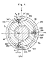
- FIG. 4 there is shown a second embodiment of the invention, in which the component parts common with the first embodiment are designated by common reference numerals, and their explanations are omitted to avoid unnecessary repetitions.
- a feature of this embodiment resides in that three hydrostatic radial bearings are used to support the radial load F R , side force F v and moment load M z about the z-axis.
- hydrostatic radial bearings 31A to 31C are constituted by: radial cylinder bores 32A to 32C which are formed on the outer periphery of the sleeve portion 4A of the bearing sleeve 4 in particular positional relations with each other similarly to the first embodiment; hydrostatic pads 33A to 33C having small-diameter rod portions slidably fitted in the cylinder bores 32A to 32C and large-diameter pad portions held in sliding contact with the inner peripheral surface of the cylindrical portion 6B of the drive disc 6; groove-like pressure chambers 34A to 34C formed on the pad surfaces in sliding contact with the drive disc; and axial throttle passages 35A to 35C formed in the pads 33A to 33C to communicate chambers in the cylinder bores 32A to 32C with the pressure chambers 34A to 34C.
- hydrostatic radial bearings 32A to 32C, hydrostatic pads 33A to 33C, pressure chambers 34A to 34C and throttle passages 35A to 35C are referred to collectively as hydrostatic radial bearing 31, cylinder bore 32, hydrostatic pad 33, pressure chamber 34 and throttle passage 35, respectively.
- hydrostatic radial bearings 31A to 31C are located in the following positional relations with each other.
- the first hydrostatic radial bearing 31A is located below the x-axis on the side of the acting point O of the resultant force of mean hydraulic reaction forces at a distance e o coinciding with the acting point O of the resultant force in distance on the x-axis; the second hydrostatic radial bearing 31B is located on the side away from the acting point O and on or in the x-axis; and the third hydrostatic radial bearing 31C is located on the side of the acting point O of the resultant force and in point symmetry with the first hydrostatic radial bearing 31A relative to the x-axis.
- the present embodiment When applied as a hydraulic pump, the present embodiment with the above-described arrangement operates in the same manner as the first embodiment.
- the three hydrostatic radial bearings 31A to 31C are located around the outer periphery of the sleeve portion 4A of the bearing sleeve 4 in the particular positional relations described above thereby to support the radial load F R , side force F v and moment load Mz.
- first and third hydrostatic radial bearings 31A and 31C are located in off-axis positions at a distance of e o from the x-axis and in point-symmetrical positions above and below the x-axis relative to the acting point O of the resultant force of mean hydraulic reaction forces. As a result the point of intersection O D .
- the y-axis components f DY and f SY can be supported in balanced state. Consequently, even if a moment M z about the z-axis is generated by a radial load F R exerted on the acting point O of the resultant force of mean hydraulic reaction forces, it can be supported in balanced state.
- the second hydrostatic radial bearing 31B is located on the x-axis on the side away from the acting point of the resultant force, it can balance the side force F v which would be exerted on the drive disc 6.
- the resultant force of the total hydraulic reaction force of pistons varies depending upon the number of pistons in the high pressure area, such variations in the resultant force can be suitably supported by the third hydrostatic radial bearing 31C.
- the second embodiment is capable of maintaining the hydrostatic pads 33A to 33C of the first to third radial bearings 31A to 31c in appropriate posture for imparting a surface pressure to the sliding surfaces of the respective pads 33A to 33C, preventing extremely inclined support thereof.
- This prevents localized abrasive wear of the hydrostatic pads 33A to 33C, and permits to maintain an oil film of uniform thickness between the sliding surfaces of the hydrostatic pads 33A to 33C and the hydrostatic bearing guide surface of the drive disc. Accordingly, it becomes possible to suppress the leaks from the sliding surfaces of the hydrostatic pads 33A to 33C to a minimum and to reduce the power losses which would result from such leaks.
- Fig. 5 Shown in Fig. 5 is a third embodiment of the invention, in which the component parts common with the first embodiment are designated by common reference numerals, and their explanations are omitted to avoid repetitions.
- a feature of this embodiment resides in that hydrostatic radial bearings are located in particular positions on the part of the casing, with the respective hydrostatic pads held in sliding contact with the outer periphery of the drive disc.
- casing 41 is constituted by a cylindrical casing body 42 having a small-diameter portion 42A and an inclined large-diameter portion 42B, and an end casing 43 closing the outer open end of the inclined portion 42B similarly to the casing of the first embodiment except that the inclined portion 42B has a greater thickness to provide hydrostatic radial bearings 47 as will be described hereinafter.
- Denoted at 44 is a bearing sleeve which is provided as a support member in the small-diameter portion 42A of the casing body 42, and which is formed substantially in a hollow cylindrical shape different from the counterpart in the first embodiment.
- the bearing sleeve 44 has one end thereof abutted against and supported by a stepped portion 42C on the inner periphery of the small-diameter portion 42A, in this case the bearing sleeve 44 incorporating only hydrostatic thrust bearings 26 of the same construction as in the first embodiment
- the reference 45 designates a rotational shaft which has an end portion 45 extended through the bearing sleeve 44 and which is provided with a drive disc 46 at the inner end of the shaft portion 45 in the casing 41.
- the drive disc 46 is formed in a circular disc-like shape.
- the rotational shaft 45 is rotatably supported by the bearing sleeve 44 through a bearing 7, and the drive disc 46 is arranged to support hydraulic reaction forces of pistons through hydrostatic thrust bearings 26 in the same manner as in the first embodiment.
- Indicated at 47 is one of hydrostatic radial bearings which are provided on the inner periphery of the inclined portion 42B of the casing 42 in four spaced positions which are in the particular positional relations as shown in Fig. 2 or in three spaced positions which are in the particular positional relations as shown in Fig. 4.
- Fig. 5 shows only one of these hydrostatic radial bearings as a representative.
- the hydrostatic radial bearing 47 is constituted by; a cylinder bore 48 formed on the inner periphery of the inclined portion 42B of the casing 42 in a position opposing the outer periphery of the drive disc 46; a hydrostatic pad 49 having a small-diameter rod portion slidably fitted in the cylinder bore 48 and a large-diameter pad portion held in sliding contact with the outer peripheral surface of the drive disc 46; a pressure chamber 50 formed in the surface of the pad 49 in sliding contact with the drive disc 46; and a throttle passage 51 for supplying a bearing control pressure to the pressure chamber 50.
- the cylinder bore 48 is supplied with high oil pressure through an oil conduit 25.
- FIG. 6 there is shown a hydraulic circuit diagram of a hydraulic system for a construction machine like power shovel, employing the bent axis type variable displacement hydraulic machine of the invention.
- Fig. 6 indicated at 101 is an engine as a drive source, at 102 and 103 are hydraulic pumps with the hydrostatic radial bearing support according to the invention, at 104 are a group of control valves for controlling distribution of fluid power from the pumps 102 and 103, at 105 is a rotating motor, at 106 is a center joint for relaying the power from the group of control valves 104, at 107 and 108 are vehicle drive hydraulic motors which are mounted on a lower vehicle body, at 109 is a bucket operating hydraulic cylinder, at 110 is an arm operating hydraulic cylinder, at 111 and 111 are a boom operating hydraulic cylinders, at 112 to 120 are conduits interconnecting the afore-mentioned hydraulic components or elements.
- the high fluid pressures which are discharged from the hydraulic pumps 102 and 103 driven from the engine 101, are fed through the control valves 104 to the rotating hydraulic motor 105 which drives the rotating mechanism, the travelling hydraulic motors 107 and 108 which drive the travelling mechanism, or the boom, bucket and arm hydraulic cylinders 109 to 111 to perform an excavating operation.
- hydraulic machines 102 and 103 for construction machine
- hydraulic pumps which can operate with high stability and reliability and with less oil leaks even when the tilt angles of the pumps 102 and 103 are increased for the purpose of enhancing the travelling and excavating powers for a higher performance. Similar effects can be produced when the invention is applied to the rotating motor 105 or to the hydraulic vehicle drive motors 107 and 108.
- the invention has been described by way of total hydrostatic support type hydraulic pumps, it is to be understood that the invention can be realized as partial hydrostatic support type machines employing the radial hydrostatic bearing 20 (31, 47) in combination with a mechanical anti-friction bearing (e.g., a roller bearing) in place of the hydrostatic thrust bearing 26.
- a mechanical anti-friction bearing e.g., a roller bearing
- the present invention is applicable to hydraulic machines which include at least a hydrostatic radial bearing
- the paired suction and discharge ports formed in the valve plate as well as the paired suction and discharge passages formed in the head casing become a high pressure port, so that it is advisable to provide a shuttle valve between the suction and discharge ports or between the suction and discharge passages, drawing out high oil pressure through the shuttle valve and supplying same as a bearing control pressure to the hydrostatic radial bearings.
- tilting mechanism 15 has been shown as being provided in the head casing 3 in the foregoing embodiments, it may be substituted with a tilting mechanism which is located on a side wall of the casing body 2 (42) and which is arranged to tilt the cylinder block and valve plate through a yoke with one end thereof supported on a trunnion within the casing.
- the hydraulic machine according to the present invention is applicable to hydraulic screw-down mechanisms for rolling mills, hydraulic systems of powder molding machines, injection molding machines, high speed foregoing machines operating in a high temperature environment. tunnel excavating machines and other hydraulically operated machines.
- the hydraulic machine of the invention is provided with a plural number of hydrostatic radial bearings in such a manner as to balance constantly the moment loads about the rotational shaft, relevant to the acting point on the drive disc of the hydraulic reaction forces varying according to the number of pistons in the high pressure area.
- This arrangement has a number of advantages as follows.
Abstract
Description
- This invention relates to a bent axis type variable displacement hydraulic machine which is suitable for use as a hydraulic pump, hydraulic motor or the like, and more particularly to a bent axis type variable displacement hydraulic machine of the type which is adapted to support a rotational shaft by partial- and/or total-hydrostatic bearings.
- Generally, a bent axis type hydraulic pump has a drive disc on a rotational shaft coupled with a cylinder block through pistons which are reciprocably received in the cylinder block. Therefore, in a case where the bent axis type hydraulic machine is applied as a hydraulic pump, the hydraulic reaction forces which act on pistons on the high pressure side in a discharge stroke are supported by the rotational shaft through the drive disc. Similarly, when applied as a hydraulic motor, the hydraulic reactions forces which act on pistons on the high pressure side in a suction (feeding) stroke are suppcorted by the rotational shaft through the drive disc.
- Accordingly, in a bent axis type hydraulic machine of this sort, the rotational shaft is subject to radial and thrust loads of the hydraulic reaction forces, and therefore it is necessary to mount the rotational shaft in a suitable condition for supporting these loads.
- In this connection, it has been the general practice in the prior art to resort to the so-called mechanical type support which mechanically supports the rotational shaft rotatably by means of ball or roller bearings capable of supporting the radial and thrust loads, the partial hydrostatic type support which mechanically supports the either the radial or thrust loads by a roller or ball bearing while supporting the other load by a hydrostatic bearing, or the total hydrostatic type support which supports the entire loads hydraulically by means of hydrostatic bearings.
- Of these various types of shaft support, a hydraulic machine employing a shaft support of the partial hydrostatic type bearing is described, for example, in Japanese Laid Open Patent Application 60-224981, wherein a rotational shaft is supported by a hydrostatic thrust bearing composed of a stationary bearing and a movable bearing, which movable bearing being provided with springs in an outer ring to counteract the thrust load which acts on the rotational shaft, along with pistons which are located on the side of the outer ring to generate a pressure in the same direction as the springs and to which oil pressure is applied from the high pressure area in the cylinder block.
- On the other hand, a hydraulic machine supporting a shaft totally with hydrostatic bearings is described in Japanese Laid-Open Patent Application 59-131776, which is provided with a radial load bearing sleeve and a thrust load bearing plate within a casing, in combination with a drive flange whioh is provided movably between the bearing sleeve and the bearing plate to serve also as a drive disc. The drive flange has one end face thereof securely connected to a rotational shaft and the other end face coupled with pistons. Further, a plural number of pressure chambers which constitute a hydrostatic radial bearing are defined between the outer peripheral surface of the drive flange and the bearing sleeve, and a plural number of drive shoes which constitute a hydrostatic thrust bearing are provided on one end face of the drive flange. The afore-mentioned pistons and drive flanges have oil passages bored therein for supplying high pressure oil independently to the hydrostatic radial and thrust bearings from the corresponding cylinders, thereby to hydrostatically support the radial and thrust loads.
- When the bent axis type variable displacement hydraulic machine is applied as a hydraulic pump, the hydraulic reaction forces acting on the pistons in the high pressure area in the discharge stroke are supported by the rotational shaft through the drive disc. In such a case, the point of exertion or the acting point of the resultant force of such hydraulic reaction forces is located in an eccentric position with respect to the axis of the rotational shaft. Besides, the positions and the number of pistons in the high pressure area changes with the rotation of the cylinder block, so that the location of the acting point of the resultant force of hydraulic reaction forces also changes with the rotation of the cylinder block, generally drawing a locus in the shape of "∞". Therefore, the center of the locus of the resultant force of hydraulic reaction forces is usually referred to as the acting point of mean hydraulic reaction force. When the bent axis type hydraulic machine is applied as a hydraulic motor, the acting point of the resultant force of hydraulic reaction force also has a varying location off the axis of the rotational shaft.
- As a result of the off-axis location of the acting point of the resultant force of hydraulic reaction force relative to the axis of the rotational shaft, the drive disc is subject not only to the radial and thrust load components but also to moment components which are induced bV the radial and thrust load components.
- However, in the prior art bent axis type hydraulic machine, especially in case of the hydraulic machine of afore-mentioned Japanese Laid-Open Patent Application 59-131776, a hydrostatic radial bearing is constituted by supplying high pressure oil from pistons to corresponding pressure chambers which are formed in 90° shifted positions between the drive flange and bearing sleeve according to the total number of the pistons, and a hydrosratic thrust bearing is constituted by supplying high pressure oil from pistons to corresponding drive shoes with pressure chambers provided on the drive flange according to the total number of the pistons, thereby supporting the radial and thrust loads and the moment load abour the rotational shaft. Namely, the conventional hydrostatic radial and thrust bearings have a load supporting capacity only in the areas on the side of the acting point of the resultant force of hydraulic reaction force where high pressure oil is supplied from the pistons, and not in the areas away from the acting point or in the areas where high oil pressure is not supplied.
- Nevertheless, the above-mentioned prior art hydraulic machine is required to support the imposed radial and thrust loads and the moment load about the rotational shaft not only by the hydrostatic bearing in the areas on the side of the acting point but also by the hydrostatic bearing in the areas away from the acting point.
- Consequently, there occurs an imbalance between the hydrostatic bearing with a load supporting capacity, which is located on the side of the acting point, and the hydrostatic bearing without a load supporting capacity, which is located on the side away from the acting point, resulting in non-uniform thickness of oil films which are formed on the sliding surfaces of the drive flange and drive shoes. This will induce metal contact of the sliding surfaces in the areas away from the acting point, accelerating localized abrasive wear of the sliding surfaces and increasing the leak flows.
- Especially, in a case where the sliding surfaces of the hydrostatic radial bearing, such as the outer peripheral surfaces of the drive flange serving as a drive disc or the inner peripheral surfaces of the bearing sleeve, are abraded during use over a long time period, the gaps between these surfaces are broadened to promote instable radial vibrations of the drive flange as well as the vibrations of contact between the piston and cylinder block. As a result, there arises a problem that the increased fletching abrasion at the contacting portions will bring about an increased degree of contacting stress of the pistons.
- The present invention contemplates to solve the above-mentioned problems of the prior art, and has as its object the provision of a bent axis type variable displacement hydraulic machine employing a partial- and/or total-hydrostatic bearing support which can ensure operations of high stability and reliability by suppressing abrasive wears in the radial direction and leak flow rate during use over a long time period.
- In accordance with the present invention, the above-stated objective is achieved by the provision of a bent axis type variable displacement hydraulic machine including: a cylindrical casing having a head casing with suction and discharge passages; a rotational shaft rotatably inserted into the casing and having a drive disc at the inner distal end received in the casing; a cylinder block located in the casing and having a plural number of axial cylinder bores; a plural number of pistons reciprocably received in the cylinder bores in the cylinder block and each pivotally supported at one end by the drive disc; a valve plate having a pair of suction and discharge ports and having on one end face in sliding contact with the cylinder block and on the other end face tiltably in sliding contact with a tilting sliding surface on head casing; a tilting mechanism for tilting the valve plate together with the cylinder block; a hydrostatic radial bearing provided between the drive disc and casing for supporting radial loads of hydraulic reaction forces acting on the drive disc in the radial and thrust directions; and oil passage for conducting oil pressure to and from the hydrostatic radial bearing through one of the paired suction and discharge ports whichever is on the high pressure side; characterized in that the hydrostatic radial bearing is located in a position for balancing a moment occurring about the rotational shaft in relation with the acting point of the resultant force of mean hydraulic reaction force acting on the drive disc in the radial direction.
- The hydraulic machine may be provided with: a drive disc of U-shape in section having a disc portion for tiltably supporting the pistons and a hollow cylindrical portion extending from the disc portion in a direction away from the cylinder block; a support member for rotatably supporting the afore-mentioned rotational shaft, located in a position adjacent one end of the casing and in a space defined between the journal portion of the rotational shaft and the sectionally U-shaped drive disc; and a hydrostatic radial bearing provided between the outer periphery of the just-mentioned support member and the inner periphery on the hollow cylindrical portion of the drive disc.
- Alternatively, the hydraulic machine may be constituted by a drive disc of a circular disc-like shape for tiltably supporting the pistons, and a hydrostatic radial bearing located between the outer periphery of the drive disc and the inner periphery of the casing.
- Further, there may be provided a number of hydrostatic radial bearings located relative to x- and y-axes which perpendicularly intersect the axis of the rotational shaft, including a first hydrostatic radial bearing located on the side of the acting point of the resultant force of mean hydraulic reaction force and beneath the x-axis and outside the shifting range of the acting point of the resultant force of the mean hydraulic reaction force, a second hydrostatic radial bearing located on the side away from the acting point of the resultant force of the mean hydraulic reaction force relative to the y-axis and on the lowerside of the x-axis, a third hydrostatic radial bearing located on the side away from the acting point of the resultant force of mean hydraulic reaction force and on or in the vicinity of the x-axis, and a fourth hydrostatic radial bearing located above the x-axis and on or in the vicinity of the y-axis.
- In this case, preferablv, the first and second hydrostatic radial bearings are located in positions satisfying the condition of
fLY x eL = fRY x eR
wherein eL is the distance along the x-axes spacing apart the center of sliding movements of rhe hydrostatic pad of the first bearing and the acting point of the resultant force of mean hydraulic reaction force, fLY is the load components acting on the first hydrostatic pad in the y-axis direction, eR is the distance along the x-axis spacing apart the center of sliding movements of the hydrostatic pad of the second bearing and the acting point ot the resultant force of mean hydraulic reaction force, and fRY is the load components acting on the second hydrostatic pad in the y-axis direction. - Further, with respect to the x- and y-axis which perpendicularly intersect the axis of the rotational shaft, there may be provided: a first hydrostatic radial bearing located beneath the x-axis and on the side of the acting point of the resultant force of mean hydraulic reaction force at the same distance as the acting point in the direction of the x-axis; a second hydrostatic radial bearing located on the side away from the acting point of the resultant force of mean hydraulic reaction force and on or in the vicinity of the x-axis; and a third hydrostatic radial bearing located on the side of the acting point of the resultant force of mean hydraulic reaction force and in a position of point symmetry with the first hydrostatic radial bearing relative to the x-axis.
- The bent axis type variable displacement hydraulic machine of the present invention is applicable as a pump of main hydraulic pressure source or as a drive motor in various hydraulic systems for construction machines.
- With the above-described arrangements, although varying hydraulic reaction forces acting on the drive disc tend to produce moments about the rotational shaft in relation with the acting point of the resultant force of mean hydraulic reaction force, the hydrostatic radial bearing is so located as to hold such moment loads about the rotational shaft constantly in balanced state, ensuring formation of an oil film of uniform thickness on the sliding surfaces to prevent abnormal abrasive wear of the sliding surfaces while reducing the leak flow rate to a minimum.
- In the accompanying drawings:
- Figs. 1 to 3 illustrate a first embodiment of the invention, of which Fig. 1 is a vertical section of a bent axis type variable displacement hydraulic machine in the first embodiment, Fig. 2 is a cross-sectional view taken on line II-II of Fig. 1, and Fig. 3 is a diagrammatic illustration explanatory of the relationship of the hydraulic reaction forces acting on the drive disc with moment and side force;
- Fig. 4 is a view similar to Fig. 2 but showing a second embodiment of the invention;
- Fig. 5 is a vertical section of a bent axis type variable displacement hydraulic machine in a third embodiment of the invention;
- Fig. 6 is a circuit diagram of a construction machine hydraulic system incorporating the machine according to the invention.
- Hereafter, the invention is described more particularly with reference to the drawings showing some preferred embodiments of the bent axis type variable displacement hydraulic machine according to the invention.
- Referring first to Figs. 1 to 3, there is shown a first embodiment of the invention, in which indicated at 1 is a casing which is constituted by a cylindrical casing body with a small-
diameter portion 2A and a large-diameter tiltedportion 2B, and ahead casing 3 closing the outer end of the tiltedportion 2B of thecasing body 2. - Designated at 4 is a bearing sleeve which is provided as a support member within the small-
diameter portion 2A of thecasing 2, the bearing sleeve 4 being constituted by asleeve portion 4A which is located in a space between anend portion 5A of arotational shaft 5, which will be described hereinafter, and acylindrical portion 6B of adrive disc 6, and aflange portion 4B which is located around the outer periphery of thesleeve portion 4A and abuttingly supported by an innerstepped portion 2C of the small-diameter portion 2A. - Indicated at 5 is the rotational shaft which is extended into the casing 1 through the bearing sleeve 4 and provided with a
drive disc 6 of sectionally U-shape integrally at its distal end in the casing 1. In this instance, thedrive disc 6 is constituted by adisc portion 6A of a larger diameter, and acylindrical portion 6B which is extended toward theflange portion 4B of the bearing sleeve 4 from the outer periphery of thedisc portion 6A. Therotational shaft 5 is rotatably supported in the bearing sleeve 4 through abearing 7, and thedrive disc 6 is arranged to support hydraulic reactions forces ofpistons 10 through hydrostatic radial andthrust bearings - The
reference 8 designates a cylinder block which is provided within the casing 1 and rotatable integrally with therotational shaft 5, thecylinder block 8 having a plural number ofpistons 10 reciprocably received incylinders 9 which are bored axially in thecylinder block 8. Thepistons 10 are each provided with aspherical portion 10A at the fore end and thereby pivotally connected to thedisc portion 6A of thedrive disc 6. - Indicated at 11 is a square valve plate which has one end face thereof in sliding contact with the opposing end face of the
cylinder block 8, and the other end face in sliding contact with a concavetilting sliding surface 12 which is formed on thehead casing 3. Thevalve plate 11 has a throughhole 11A bored at the center thereof to receive from the opposite sides the tip ends of acenter shaft 13 and a rockingpin 19 which will be described hereinafter. Thevalve plate 11 is further provided with a pair of suction and discharge ports (not shown) which are intermittently communicated with thecylinders 9 during rotation of thecylinder block 8. Irrespective of the tilted position of thevalve plate 11, the suction and discharge ports are communicated respectively with a pair of suction and discharge passages (not shown) which are provided in thehead casing 3 and opened to the tilting slidingsurface 12. - Denoted at 13 is a center shaft which tiltably supports the
cylinder block 8 between thedrive disc 6 and thevalve plate 11, and has at one end aspherical portion 13A which is pivotally supported in a center position of thedrive disc 6. The other end of thecenter shaft 13, which is protruded through thecylinder block 8, is slidably received in athrough hole 11A which is bored at the center of thevalve plate 11 for centering thecylinder block 8 and thevalve plate 11. Thereference 14 denotes a compression spring which serves to apply a predetermined pressure to the sliding surfaces of thecylinder block 8 andvalve plate 11. - Designated at 15 is a tilting mechanism which is mounted in the
head casing 3 for tilting thevalve plate 11 along the tilting/slidingsurface 12. Thetilting mechanism 15 is constituted by a steppedcylinder bore 16 formed in thehead casing 3 and having oil passages 19A and 19B at the opposite ends thereof, aservo piston 18 slidably fitted in thecylinder bore 16 and definingoil chambers pin 19 fitted in theservo piston 18 and having a spherical portion at its distal end pivotally fitted in thevalve plate 11. The oil pressure which is received from an auxiliary pump through a tilting control valve (both not shown) is supplied to theoil chamber oil passage servo piston 18 to tilt thevalve plate 11 andcylinder block 8. - The
reference numerals 20A to 20D indicate first to fourth hydrostatic radial bearings, respectively, which support the radial load components of mean hydraulic reaction force acting on thedrive disc 6. As shown in Fig. 2, these hydrostaticradial bearings 20A to 20D are constituted by:radial cylinder bores 21A to 21D which are formed on the outer periphery of thesleeve portion 4A of the bearing sleeve 4 in a particular relationship as will be explained hereinafter;hydrostatic pads 22A to 22D having small-diameter rod portions slidably fitted in thecylinder bores 21A to 21D and large-diameter pad portions positioned outside thecylinder bores 21A to 21D and held in sliding contact with the inner peripheral surface (hydrostatic bearing guide surface) of thecylindrical portion 6B of the drive disc; groove-like pressure chambers 23A to 23D formed on the outer surfaces of the pad portions of thehydrostatic pads 22A to 22D which are in sliding contact with the drive disc; andaxial throttle passages 24A to 24D formed on thehydrostatic pads 22A to 22D to communicate the chambers in thecylinder bores 21A to 21D with therespective pressure chambers 23A to 23D. The hydrostaticradial bearings 20A to 20D, cylinder bores 21A to 21D,hydrostatic pads 22A to 22D,pressure chambers 23A to 23D andthrottle passages 24A to 24D are hereafter collectively referred to as hydrostaticradial bearing 20, cylinder bore 21,hydrostatic pad 22,pressure chamber 23 andthrottle passage 24, respectively. - Indicated at 25 are oil passages which are formed in the casing 1 and bearing sleeve 4 to supply a bearing control pressure constantly to the hydrostatic
radial bearings 20A to 20D. To draw in the high pressure oil which is sucked or discharged through one of the paired suction and discharge ports in thevalve plate 11, theoil passages 25 are opened at one end to the suction or discharge port whichever is on the higher pressure side, to the suction or discharge passage of thehead casing 3 whichever is on the higher pressure side, or to a high pressure piping outside the casing 1, and at the other end to the cylinder bores 21A to 21D of the hydrostaticradial bearings 20A to 20D to supply a bearing control pressure to therespective pressure chambers 23A to 23D. If desired, theoil passages 25 may be substituted with external pipings which run outside the casing 1. - The hydrostatic
radial bearings 20A to 20D are located in a particular positional relationship as follows. - Referring to Fig. 3, with respect to axes x and y which perpendicularly intersect the axis z of the
rotational shaft 5 on the front side of thedrive disc 6, the resultant force of mean hydraulic reaction force ofpistons 10 in the high pressure area has its acting point at 0 which is spaced from the point of intersection of the x- and y-axes by a distance eo in the direction of the x-axis. In this instance, the point 0 is referred to as an acting point of the resultant force of mean hydraulic reaction force, because the hydraulic reaction force F varies in the fashion of the symbol "∞" according to the number of pistons in the high pressure area. - The radial and thrust loads FR and FT imposed by the above-mentioned hydraulic reaction force F are expressed as
FR = F sin α
FT = F cos α (1)
wherein α is the tilting angle of thecylinder block 8. When the tilting angle α is minimum, the radial load FR becomes minimum and the thrust load FT becomes maximum. On the other hand, when the tilting angle α is maximum, the radial and thrust loads FR and FT become maximum and minimum, respectively. - With respect to the positional relations of the hydrostaric
radial bearings 20A to 20D, the first hydrostaticradial bearing 20A is located on the side of the acting point 0 of the resultant hydraulic reaction force and outside the shifting range of the acting point 0 of the resultant force which shifts in the shape of "∞" (on the left side of the acting point 0 in Fig. 2). The second hydrostaticradial bearing 20B is located on one side of the y-axis away from the acting point 0 of the resultant force (to the right of the y-axis in Fig. 2) and beneath the x-axis, in a particular positional relationship with the first hydrostaric bearing 20A as will be explained hereinafter. The third hydrostaticradial bearing 20C is located on the side away from the acting point of the resultant force to the right of the y-axis) and on or in the vicinity of the x-axis. The fourth hydrostatic radial bearing 20D is located above the x-axis and on or in the vicinity of the y-axis. - With regard to the first hydrostatic
radial bearing 20A, it is considered that tbe radial load fL which is exerted at the point of intersection OL, where the axis of thehydrostatic pad 22A intersects the inner peripheral surface of thecylindrical portion 6B of thedrive disc 6, has a component fLX of the x-axis direction and a component fLY of the y-axis direction, and that the acting point O of the resultant force is spaced from the point of intersection OL by a distance eL in the direction of the x-axis. With regard to the second hydrostaticradial bearing 20B, it is considered that the radial load fR which is exerted at the point of intersection OR, where the axis of thehydrostatic pad 22B intersects the inner peripheral surface of thecylindrical portion 6B, has a component fRX of the x-axis direction and a component fRY of the y-axis direction, and that the acting point O of the resultant force is spaced from the point of intersection OR by a distance eR. Under these conditions, the first and second hydrostaticradial bearings
fLY x eL = fLX x eR (2)
By so locating, they act to balance the moment loads Mz about the z-axis as will be explained hereinafter. - Further, in Fig. 1, the
reference numeral 26 denotes hydrostatic thrust bearings which are each constituted, similarly to the above-described hydrostaticradial bearing 20, by an axial cylinder bore 27 formed into the inner end face of thesleeve portion 4A of the bearing sleeve 4, ahydrostatic pad 28 having a small-diameter rod portion slidably fitted in the cylinder bore 27 and a large-diameter pad portion held in sliding contact with the inner end face (hydrostatic bearing guide surface) of thesleeve portion 4A, a groove-like pressure chamber 29 formed on the pad portion of thehydrostatic pad 29, and athrottle passage 30 bored in thehydrostatic pad 28 in such a manner as to communicate a chamber in the cylinder bore 27 with thepressure chamber 29. From one of the suction and discharge port whichever is on the high pressure side, the chamber in the cylinder bore 27 of thehydrostatic thrust bearing 26 is constantly supplied with high pressure oil through the afore-mentionedpassages 25. Although only onehydrostatic thrust bearing 26 is shown in Fig. 1, a plural number of thrust bearings of the same construction may be provided around thesleeve portion 4A of the bearing sleeve 4 to balance the moment loads about the x- and y-axes in a manner similar to the above-described hydrostaticradial bearings 20. - When applied as a hydraulic pumps the bent axis type variable displacement hydraulic machine of this embodiment operates in the following manner.
- Firstly, the
valve plate 11 is tilted to the maximum tilted position of Fig. 1 together with thecylinder block 8 by operation of thetilting mechanism 15. For this purpose, theservo piston 18 is displaced by supplying oil pressure from the auxiliary pump to theoil chamber 17A in the cylinder bore 16. By so doing, the pivotingpin 19 is displaced together with theservo piston 18, tilting thevalve plate 11 under guidance of the tiltingguide surface 12. Consequently, thecylinder block 8 is tilted integrally with thecenter shaft 13 into the position shown in Fig. 1, with its rotational axis inclined relative to the axis of therotational shaft 5. - Nextly, the
rotational shaft 5 is rotated by an engine, electric motor or other suitable drive source, whereupon thecylinder block 8 is rotated integrally with therotational shaft 5 since thedrive disc 6 of therotational shaft 5 is connected to thepistons 10 in therespective cylinders 9 of thecylinder block 8. Consequently, thepistons 10 are reciprocated in therespective cylinders 9 during rotation of thecylinder block 8. In the suction stroke when eachpiston 10 is moved away from thecylinder 9, the operating oil is drawn into thecylinder 9 from a suction/discharge passage through a suction/discharge port, and, in the discharge stroke when thepiston 10 is moved into thecylinder 9, the operating oil in thecylinder 9 is pressurized and discharged through a suction/discharge port and a suction/discharge passage. - In this connection, in a bent axis type hydraulic pump of this sort, in proportion to the number of pistons serving for generating the discharge pressure (e.g., in case the total number of pistons is seven, the maximum number of pressurizing pistons is four, the minimum number of pressurizing pistons is three, and the average number of pressurizing pistons is 3.5), the load of hydraulic reaction force is exerted on the
drive disc 6 in synchronism with the rotational speed of therotational shaft 5. The load which is exerted on thedrive disc 6 is diffused at the support surface of thespherical portion 10A into radial load FR with radial components and thrust load FT with axial components. In this instance, with respect to the x- and y-axes which perpendicularly intersect the axis of therotarional shaft 5, moment loads about the x-, y- and z-axes are induced by the hydraulic reaction forces resulting from piston operations. These loads consisting of the loads of hydraulic reaction forces of pistons and the moment loads are supported by the hydrostatic radial andthrust bearings hydrosratic pads pressure chambers pads hydrostatic bearings - Now, the manner of supporting the radial component of the loads, which are exerted on the
drive disc 6, is explained more particularly with reference to Fig. 3. - As mentioned hereinbefore, the radial component load FR of the overall hydraulic reaction force F of pistons is shifted in the fashion of "∞" about the acting point O of the resultant force of mean hydraulic reaction force according to the number of pistons in high pressure areas on the side of the acting point O. Besides, the radial load FR varies in synchronism with the number of pistons in the high pressure area, the load becoming zero at a tilt angle α of 0° and becoming maximum at the maximum tilt angle.
- Therefore, in the present embodiment, four hydrostatic
radial bearings 20A to 20D are located around the outer periphery of thesleeve portion 4A of the bearing sleeve 4 in the particular positional relations as shown in Fig. 2. In addition to the radial load FR which is imposed on thedrive disc 6, the moment load Mz about the axis z of therotational shaft 5 is supported by these hydrostaticradial bearings 20A to 20D. - More specifically, since the acting point O of the resultant force of mean hydraulic reaction force is deviated from the axis z of the
rotarional shaft 5 by the distance eo, the moment load Mz about the z-axis is turned into a moment relevant to the acting point O of the resultant force when the radial load FR is exerted on the acting point O. - However, in the present embodiment, the first hydrostatic
radial bearing 20A is located on the side of the acting point O of the resultant force of mean hydraulic reaction force, and the second hydrostaticradial bearing 20B is located on the side away from the acting point of the resultant force, in the particular positional relationship of the Equation (2) given hereinbefore, so that they can support the moment load Mz about the z-axis, relevant to the acting point of the resultant force, in balanced state. - Further, side force is generated in the sliding portion of the
valve plate 11 depending upon the shape or other factors of the suction/discharge port which is on the high pressure side. Through thepistons 10 or center joint 13, this side force acts on thedrive disc 6 as Fv in the direction indicated by an arrow in Fig. 3. However, in the present embodiment, the third hydrostaticradial bearing 20C is located on the side away from the acting point of the resultant force and on the x-axis, so that the high pressure oil introduced into itspressure chamber 23B imposes an inverse radial force to thedrive disc 6 to counteract the side force Fv. As a result, it becomes possible to support the side force Fv by the third hydrostaticradial bearing 20C and to balance the side force Fv by adjusting the inverse radial force. - Further, the resultant force of the hydraulic reaction force F of pistons varies depending upon the number of pistons in the high pressure area, with variations in the direction of the y-axis (in the upward and downward directions). However, in the present embodiment, the fourth hydrostatic radial bearing 20D is located above the x-axis and on the y-axis, so that the variations in the resultant force of the hydraulic reaction forces, which are caused by variations in the number of pistons in the high pressure area, can be suitably supported by the fourth hydrostatic radial bearing 20D.
- Thus, according to the present embodiments the radial load FR exerted on the acting point of the resultant force is satisfactorily supported by the first to fourth hydrostatic
radial bearings 20A to 20D in the above-described manner. In this instance, the first and second hydrostaticradial bearings radial bearings 20C and 20D, respectively. - Therefore, the first to fourth hydrostatic
radial bearings 20A to 20D can maintain the respectivehydrostatic pads 22A to 22D constantly in an appropriate posture to impart a suitable surface pressure to the sliding surfaces of therespective pads 22A to 22D, thereby precluding extremely inclined support. As a result, it becomes possible to prevent localized abrasive wear of thehydrostatic pads 22A to 22D and to maintain an oil film of uniform thickness between the sliding surfaces of thehydrostatic pads 22A to 22D and the hydrostatic bearing guide surface of the drive disc. Accordingly, the leaks from the sliding surface of the respectivehydrostatic pads 22A to 22D, which would lead to power losses, can be suppressed to a minimum. - Referring now to Fig. 4, there is shown a second embodiment of the invention, in which the component parts common with the first embodiment are designated by common reference numerals, and their explanations are omitted to avoid unnecessary repetitions.
- A feature of this embodiment resides in that three hydrostatic radial bearings are used to support the radial load FR, side force Fv and moment load Mz about the z-axis.
- More specifically, in Fig. 4, indicated at 31A to 31C are hydrostatic radial bearings employed in this embodiment. These hydrostatic
radial bearings 31A to 31C are constituted by: radial cylinder bores 32A to 32C which are formed on the outer periphery of thesleeve portion 4A of the bearing sleeve 4 in particular positional relations with each other similarly to the first embodiment;hydrostatic pads 33A to 33C having small-diameter rod portions slidably fitted in the cylinder bores 32A to 32C and large-diameter pad portions held in sliding contact with the inner peripheral surface of thecylindrical portion 6B of thedrive disc 6; groove-like pressure chambers 34A to 34C formed on the pad surfaces in sliding contact with the drive disc; andaxial throttle passages 35A to 35C formed in thepads 33A to 33C to communicate chambers in the cylinder bores 32A to 32C with thepressure chambers 34A to 34C. High oil pressure is constantly led to the cylinder bores 32A to 32C through thepassages 25. Hereafter, the hydrostaticradial bearings 32A to 32C,hydrostatic pads 33A to 33C,pressure chambers 34A to 34C andthrottle passages 35A to 35C are referred to collectively as hydrostatic radial bearing 31, cylinder bore 32, hydrostatic pad 33, pressure chamber 34 and throttle passage 35, respectively. - The above-mentioned hydrostatic
radial bearings 31A to 31C are located in the following positional relations with each other. - The first hydrostatic
radial bearing 31A is located below the x-axis on the side of the acting point O of the resultant force of mean hydraulic reaction forces at a distance eo coinciding with the acting point O of the resultant force in distance on the x-axis; the second hydrostaticradial bearing 31B is located on the side away from the acting point O and on or in the x-axis; and the third hydrostaticradial bearing 31C is located on the side of the acting point O of the resultant force and in point symmetry with the first hydrostaticradial bearing 31A relative to the x-axis. - When applied as a hydraulic pump, the present embodiment with the above-described arrangement operates in the same manner as the first embodiment.
- In this embodiment, the three hydrostatic
radial bearings 31A to 31C are located around the outer periphery of thesleeve portion 4A of the bearing sleeve 4 in the particular positional relations described above thereby to support the radial load FR, side force Fv and moment load Mz. - More specifically, the first and third hydrostatic
radial bearings hydrostatic pad 33A of the firstradial bearing 31A intersects the inner peripheral surface of thecylindrical portion 6B of thedrive disc 6, is located at the same distance from the acting point O of the resultant forces as the point of intersection OS where the axis of thehydrostatic pad 33C of the thirdradial bearing 31C intersects the inner peripheral surface of thecylindrical portion 6B, and the mean hydraulic reaction force exerted on the acting point of the resultant force has the same lines of action with respect to the first and third hydrostaticradial bearings - Thus, of the components fDX and fDY in the x- and y-axis directions of the radial load fD exerted on the point of intersection OD on the side of the first hydrostatic
radial bearing 31A and the components fSX and FSY in the x- and y-axes directions of the radial load fS exerted on the point intersection OS on the side of the third hydrostaticradial bearing 31C, the y-axis components fDY and fSY can be supported in balanced state. Consequently, even if a moment Mz about the z-axis is generated by a radial load FR exerted on the acting point O of the resultant force of mean hydraulic reaction forces, it can be supported in balanced state. - Further, since the second hydrostatic
radial bearing 31B is located on the x-axis on the side away from the acting point of the resultant force, it can balance the side force Fv which would be exerted on thedrive disc 6. - Furthermore, although the resultant force of the total hydraulic reaction force of pistons varies depending upon the number of pistons in the high pressure area, such variations in the resultant force can be suitably supported by the third hydrostatic
radial bearing 31C. - In this manner, similarly to the first embodiment, the second embodiment is capable of maintaining the
hydrostatic pads 33A to 33C of the first to thirdradial bearings 31A to 31c in appropriate posture for imparting a surface pressure to the sliding surfaces of therespective pads 33A to 33C, preventing extremely inclined support thereof. This prevents localized abrasive wear of thehydrostatic pads 33A to 33C, and permits to maintain an oil film of uniform thickness between the sliding surfaces of thehydrostatic pads 33A to 33C and the hydrostatic bearing guide surface of the drive disc. Accordingly, it becomes possible to suppress the leaks from the sliding surfaces of thehydrostatic pads 33A to 33C to a minimum and to reduce the power losses which would result from such leaks. - Shown in Fig. 5 is a third embodiment of the invention, in which the component parts common with the first embodiment are designated by common reference numerals, and their explanations are omitted to avoid repetitions.
- A feature of this embodiment resides in that hydrostatic radial bearings are located in particular positions on the part of the casing, with the respective hydrostatic pads held in sliding contact with the outer periphery of the drive disc.
- More specifically, in Fig. 5, indicated at 41 is a casing of this embodiment, which
casing 41 is constituted by a cylindrical casing body 42 having a small-diameter portion 42A and an inclined large-diameter portion 42B, and anend casing 43 closing the outer open end of theinclined portion 42B similarly to the casing of the first embodiment except that theinclined portion 42B has a greater thickness to provide hydrostaticradial bearings 47 as will be described hereinafter. - Denoted at 44 is a bearing sleeve which is provided as a support member in the small-
diameter portion 42A of the casing body 42, and which is formed substantially in a hollow cylindrical shape different from the counterpart in the first embodiment. The bearingsleeve 44 has one end thereof abutted against and supported by a steppedportion 42C on the inner periphery of the small-diameter portion 42A, in this case the bearingsleeve 44 incorporating onlyhydrostatic thrust bearings 26 of the same construction as in the first embodiment - The
reference 45 designates a rotational shaft which has anend portion 45 extended through the bearingsleeve 44 and which is provided with adrive disc 46 at the inner end of theshaft portion 45 in thecasing 41. In this embodiment, thedrive disc 46 is formed in a circular disc-like shape. Therotational shaft 45 is rotatably supported by the bearingsleeve 44 through abearing 7, and thedrive disc 46 is arranged to support hydraulic reaction forces of pistons throughhydrostatic thrust bearings 26 in the same manner as in the first embodiment. - Indicated at 47 is one of hydrostatic radial bearings which are provided on the inner periphery of the
inclined portion 42B of the casing 42 in four spaced positions which are in the particular positional relations as shown in Fig. 2 or in three spaced positions which are in the particular positional relations as shown in Fig. 4. Fig. 5 shows only one of these hydrostatic radial bearings as a representative. The hydrostaticradial bearing 47 is constituted by; a cylinder bore 48 formed on the inner periphery of theinclined portion 42B of the casing 42 in a position opposing the outer periphery of thedrive disc 46; a hydrostatic pad 49 having a small-diameter rod portion slidably fitted in the cylinder bore 48 and a large-diameter pad portion held in sliding contact with the outer peripheral surface of thedrive disc 46; a pressure chamber 50 formed in the surface of the pad 49 in sliding contact with thedrive disc 46; and a throttle passage 51 for supplying a bearing control pressure to the pressure chamber 50. The cylinder bore 48 is supplied with high oil pressure through anoil conduit 25. - In this embodiment with the above arrangements, the four or three hydrostatic
radial bearings 47 which are located in the particular positional relations as shown in Fig. 2 or Fig. 4 operate in the same manner and have the same effects as in the foregoing embodiments. - Referring to Fig. 6, there is shown a hydraulic circuit diagram of a hydraulic system for a construction machine like power shovel, employing the bent axis type variable displacement hydraulic machine of the invention.
- In Fig. 6, indicated at 101 is an engine as a drive source, at 102 and 103 are hydraulic pumps with the hydrostatic radial bearing support according to the invention, at 104 are a group of control valves for controlling distribution of fluid power from the
pumps control valves 104, at 107 and 108 are vehicle drive hydraulic motors which are mounted on a lower vehicle body, at 109 is a bucket operating hydraulic cylinder, at 110 is an arm operating hydraulic cylinder, at 111 and 111 are a boom operating hydraulic cylinders, at 112 to 120 are conduits interconnecting the afore-mentioned hydraulic components or elements. - With the construction machine hydraulic system arranged in the above-described manner, the high fluid pressures, which are discharged from the
hydraulic pumps engine 101, are fed through thecontrol valves 104 to the rotatinghydraulic motor 105 which drives the rotating mechanism, the travellinghydraulic motors hydraulic cylinders 109 to 111 to perform an excavating operation. - In a case where the hydraulic machine of the present invention is applied as
hydraulic pumps pumps rotating motor 105 or to the hydraulicvehicle drive motors - Although the invention has been described by way of total hydrostatic support type hydraulic pumps, it is to be understood that the invention can be realized as partial hydrostatic support type machines employing the radial hydrostatic bearing 20 (31, 47) in combination with a mechanical anti-friction bearing (e.g., a roller bearing) in place of the
hydrostatic thrust bearing 26. In short, the present invention is applicable to hydraulic machines which include at least a hydrostatic radial bearing - In case the hydraulic machine of the present invention is applied as a reversible hydraulic motor, the paired suction and discharge ports formed in the valve plate as well as the paired suction and discharge passages formed in the head casing become a high pressure port, so that it is advisable to provide a shuttle valve between the suction and discharge ports or between the suction and discharge passages, drawing out high oil pressure through the shuttle valve and supplying same as a bearing control pressure to the hydrostatic radial bearings.
- Further, although the
tilting mechanism 15 has been shown as being provided in thehead casing 3 in the foregoing embodiments, it may be substituted with a tilting mechanism which is located on a side wall of the casing body 2 (42) and which is arranged to tilt the cylinder block and valve plate through a yoke with one end thereof supported on a trunnion within the casing. - In addition to the examples of application give above, the hydraulic machine according to the present invention is applicable to hydraulic screw-down mechanisms for rolling mills, hydraulic systems of powder molding machines, injection molding machines, high speed foregoing machines operating in a high temperature environment. tunnel excavating machines and other hydraulically operated machines.
- As clear from the foregoing particular description, the hydraulic machine of the invention is provided with a plural number of hydrostatic radial bearings in such a manner as to balance constantly the moment loads about the rotational shaft, relevant to the acting point on the drive disc of the hydraulic reaction forces varying according to the number of pistons in the high pressure area. This arrangement has a number of advantages as follows.
- (1) It becomes possible to form an oil film of uniform thickness between the drive disc and sliding surfaces of the hydrostatic radial bearings, and therefore to prevent abnormal abrasive wear of the sliding surfaces of the hydrostatic bearing pads and the hydrostatic bearing guide surface of the drive disc, ensuring sufficient durability even in operations over a long period of time.
- (2) In relation with the item (1) above, the formation of an oil film of uniform thickness between sliding surfaces will lead to suppression of oil leaks from the sliding surfaces to a minimal rate and therefore to reduction fo power losses.
- (3) One of the hydrostatic radial bearings, which is located in a position away from the acting point of the resultant force and on or in the vicinity of the x-axis, can stably support the side forces acting on the drive disc.
- (4) Another one of the radial hydrostatic bearings, which is located above the x-axis and on or in the vicinity of the y-axis, can stably support variant components of the radial loads exerted by hydraulic reaction forces.
Claims (7)
said hydrostatic radial bearing (20;31;47) is located in a position for balancing moment loads occurring about said rotational shaft (5;45) in relation with an acting point (0) of the resultant force of mean hydraulic reaction forces on said drive disc(6;46).
fLY x eL = fRY x eR
where eL is the distance along said x-axis spacing apart the center of sliding movement of said hydrostatic pad (22A) of said first hydrostatic radial bearing (20A) and said acting point (0) of the resultant force of mean hydraulic reaction forces, fLY is the load components acting on the hydrostatic pad (22A) of said first bearing (20A) in the y-axis direction, eR is the distance along said x-axis spacing apart the center of sliding movement of said hydrostatic pad (22B) of said second hydrostatic radial bearing (20B) and said acting point (0) of said resultant force of mean hydraulic reaction forces, and fRY is the load component acting on the hydrostatic pad (22B) of said second bearing (20B) in the y-axis direction.
Applications Claiming Priority (2)
| Application Number | Priority Date | Filing Date | Title |
|---|---|---|---|
| JP183287/89 | 1989-07-15 | ||
| JP1183287A JPH0347482A (en) | 1989-07-15 | 1989-07-15 | Slant shaft type liquid pressure machine with variable capacity |
Publications (3)
| Publication Number | Publication Date |
|---|---|
| EP0409084A2 true EP0409084A2 (en) | 1991-01-23 |
| EP0409084A3 EP0409084A3 (en) | 1992-02-26 |
| EP0409084B1 EP0409084B1 (en) | 1995-04-12 |
Family
ID=16133014
Family Applications (1)
| Application Number | Title | Priority Date | Filing Date |
|---|---|---|---|
| EP90113359A Expired - Lifetime EP0409084B1 (en) | 1989-07-15 | 1990-07-12 | Bent axis type variable displacement hydraulic machine |
Country Status (5)
| Country | Link |
|---|---|
| US (1) | US5094144A (en) |
| EP (1) | EP0409084B1 (en) |
| JP (1) | JPH0347482A (en) |
| KR (1) | KR940007755B1 (en) |
| DE (1) | DE69018532T2 (en) |
Cited By (4)
| Publication number | Priority date | Publication date | Assignee | Title |
|---|---|---|---|---|
| US5231912A (en) * | 1988-10-03 | 1993-08-03 | Hitachi Construction Machinery Co., Ltd. | Bent axis type variable displacement hydraulic machine |
| AT513773A1 (en) * | 2012-12-18 | 2014-07-15 | Wacker Neuson Linz Gmbh | Travel drive for a mobile work machine |
| CN103967732A (en) * | 2013-01-28 | 2014-08-06 | 日立建机株式会社 | Variable volume type inclined-shaft hydraulic pump |
| CN106593800A (en) * | 2015-10-16 | 2017-04-26 | 熵零控股股份有限公司 | Positive feedback plunger fluid mechanism |
Families Citing this family (13)
| Publication number | Priority date | Publication date | Assignee | Title |
|---|---|---|---|---|
| US5279185A (en) * | 1992-09-09 | 1994-01-18 | Unipat Ag | Bevel gear support with fluid bearings for radial piston hydrostatic machine |
| US6996982B2 (en) * | 2003-12-09 | 2006-02-14 | The United States Of America As Represented By The Administrator Of The Environmental Protection Agency | Method and device for switching hydraulic fluid supplies, such as for a hydraulic pump/motor |
| US7305914B2 (en) * | 2004-01-28 | 2007-12-11 | The United States Of America, As Represented By The Administrator Of The Environmental Protection Agency | Hydraulic actuator control valve |
| US7594802B2 (en) * | 2004-04-21 | 2009-09-29 | The United States Of America As Represented By The Administrator Of The U.S. Environmental Protection Agency | Large angle sliding valve plate pump/motor |
| US7553085B2 (en) * | 2006-04-28 | 2009-06-30 | The United States Of America As Represented By The United States Environmental Protection Agency | Fluid bearing and method of operation |
| US7757598B2 (en) * | 2007-10-29 | 2010-07-20 | Parker-Hannifin Corporation | Hydrostatic bearing arrangement for pump swashplate having secondary angle |
| US8096228B1 (en) | 2008-08-08 | 2012-01-17 | Sauer-Danfoss Inc. | Bent axis dual yoke hydromodule |
| US20100116579A1 (en) * | 2008-11-11 | 2010-05-13 | Sauer-Danfoss Inc. | Bent axis hydromodule with bolt on trunnion bearing carriers |
| DE102009058332B4 (en) * | 2009-12-15 | 2019-11-28 | Robert Bosch Gmbh | axial piston |
| CN102242700A (en) * | 2011-06-28 | 2011-11-16 | 张坚 | Novel variable oil pump |
| AU2014270792B2 (en) * | 2013-05-22 | 2017-08-31 | Hydac Drive Center Gmbh | Axial piston pump having a swash-plate type construction |
| CN105545835B (en) * | 2015-12-18 | 2017-06-06 | 哈尔滨工业大学 | A kind of parallel connection type inclined shaft type hydraulic transformer |
| CN113586382B (en) * | 2021-08-23 | 2022-11-08 | 苏州力源液压有限公司 | Eccentric wear eliminating method for oil distribution disc of high-pressure plunger variable pump |
Citations (2)
| Publication number | Priority date | Publication date | Assignee | Title |
|---|---|---|---|---|
| US4546692A (en) * | 1982-10-22 | 1985-10-15 | Hydromatik Gmbh | Radial bearing for drive plate of inclined-axis type axial piston machine |
| EP0257621A2 (en) * | 1986-08-25 | 1988-03-02 | Hitachi, Ltd. | Thrust hydrostatic bearing device for use in axial piston machine |
Family Cites Families (3)
| Publication number | Priority date | Publication date | Assignee | Title |
|---|---|---|---|---|
| US2967491A (en) * | 1953-01-24 | 1961-01-10 | Wiggermann Georg | Rotary piston pumps |
| DE2412619A1 (en) * | 1974-03-15 | 1975-09-25 | Linde Ag | BEARING FOR THE DRIVE FLANGE OF AN AXIAL PISTON MACHINE |
| DE3119033A1 (en) * | 1981-05-13 | 1982-12-09 | Linde Ag, 6200 Wiesbaden | DRIVE FLANGE AXIAL PISTON MACHINE WITH DRIVE SHAFT BEARING IN BEARINGS |
-
1989
- 1989-07-15 JP JP1183287A patent/JPH0347482A/en active Pending
-
1990
- 1990-07-12 DE DE69018532T patent/DE69018532T2/en not_active Expired - Fee Related
- 1990-07-12 EP EP90113359A patent/EP0409084B1/en not_active Expired - Lifetime
- 1990-07-13 KR KR1019900010626A patent/KR940007755B1/en not_active IP Right Cessation
- 1990-07-16 US US07/552,521 patent/US5094144A/en not_active Expired - Fee Related
Patent Citations (2)
| Publication number | Priority date | Publication date | Assignee | Title |
|---|---|---|---|---|
| US4546692A (en) * | 1982-10-22 | 1985-10-15 | Hydromatik Gmbh | Radial bearing for drive plate of inclined-axis type axial piston machine |
| EP0257621A2 (en) * | 1986-08-25 | 1988-03-02 | Hitachi, Ltd. | Thrust hydrostatic bearing device for use in axial piston machine |
Cited By (6)
| Publication number | Priority date | Publication date | Assignee | Title |
|---|---|---|---|---|
| US5231912A (en) * | 1988-10-03 | 1993-08-03 | Hitachi Construction Machinery Co., Ltd. | Bent axis type variable displacement hydraulic machine |
| AT513773A1 (en) * | 2012-12-18 | 2014-07-15 | Wacker Neuson Linz Gmbh | Travel drive for a mobile work machine |
| AT513773B1 (en) * | 2012-12-18 | 2015-03-15 | Wacker Neuson Linz Gmbh | Travel drive for a mobile work machine |
| US10151305B2 (en) | 2012-12-18 | 2018-12-11 | Wacker Neuson Linz Gmbh | Bent-axis machine having minimum non-zero pivot angle |
| CN103967732A (en) * | 2013-01-28 | 2014-08-06 | 日立建机株式会社 | Variable volume type inclined-shaft hydraulic pump |
| CN106593800A (en) * | 2015-10-16 | 2017-04-26 | 熵零控股股份有限公司 | Positive feedback plunger fluid mechanism |
Also Published As
| Publication number | Publication date |
|---|---|
| DE69018532T2 (en) | 1995-09-07 |
| JPH0347482A (en) | 1991-02-28 |
| DE69018532D1 (en) | 1995-05-18 |
| EP0409084B1 (en) | 1995-04-12 |
| KR910003258A (en) | 1991-02-27 |
| KR940007755B1 (en) | 1994-08-24 |
| EP0409084A3 (en) | 1992-02-26 |
| US5094144A (en) | 1992-03-10 |
Similar Documents
| Publication | Publication Date | Title |
|---|---|---|
| EP0409084B1 (en) | Bent axis type variable displacement hydraulic machine | |
| KR900003793B1 (en) | Thrust hydrostatic bearing device for use in axial piston machine | |
| KR100918603B1 (en) | Inclined shaft-type variable displacement pump/motor | |
| JPH0299782A (en) | Variable capacity type inclined shaft type hydraulic machinery | |
| EP0793018B1 (en) | Swash plate angle changing device for swash plate type piston pump motor | |
| JPH0942146A (en) | Axial piston machine | |
| US3961563A (en) | Axial piston machine of the type having a tiltable cylinder block | |
| US20090110564A1 (en) | Hydrostatic bearing arrangement for pump swashplate having secondary angle | |
| US5231912A (en) | Bent axis type variable displacement hydraulic machine | |
| US3661055A (en) | Multi-cylinder barrel hydraulic pumps or motors | |
| EP1760313A1 (en) | Variable displacement swash plate-type hydraulic rotating machine | |
| EP1167760B1 (en) | Swash plate type compressor | |
| US6010311A (en) | Hydraulic radial piston machines | |
| JPH11193781A (en) | Variable capacity type compression machine | |
| JPH03253775A (en) | Variable-displacement inclined shaft type hydraulic machine | |
| JP3778715B2 (en) | Swash plate type piston pump motor | |
| JP3569759B2 (en) | Variable capacity swash plate type hydraulic machine | |
| US4011796A (en) | Radial hydraulic pump or motor with improved pistons and slippers | |
| JPS6355374A (en) | Thrust static pressure bearing supporting device for total static pressure bearing support type axial piston machine | |
| JPH03141872A (en) | Bent axis type liquid pressure machine with variable capacity | |
| JPH04140482A (en) | Variable displacement bent axis type fluid pressure machine | |
| JPS62121873A (en) | Fully static pressure bearing bent axis type axial piston pump | |
| KR100387767B1 (en) | Swash plate type 2 speed hydraulic motor | |
| JP2816145B2 (en) | Thrust hydrostatic bearing support device for all-hydrostatic bearing-supported axial piston machine | |
| JPH04194373A (en) | Axial piston type hydraulic machinery |
Legal Events
| Date | Code | Title | Description |
|---|---|---|---|
| PUAI | Public reference made under article 153(3) epc to a published international application that has entered the european phase |
Free format text: ORIGINAL CODE: 0009012 |
|
| AK | Designated contracting states |
Kind code of ref document: A2 Designated state(s): DE FR GB IT SE |
|
| PUAL | Search report despatched |
Free format text: ORIGINAL CODE: 0009013 |
|
| AK | Designated contracting states |
Kind code of ref document: A3 Designated state(s): DE FR GB IT SE |
|
| RHK1 | Main classification (correction) |
Ipc: F04B 1/20 |
|
| 17P | Request for examination filed |
Effective date: 19920814 |
|
| 17Q | First examination report despatched |
Effective date: 19930928 |
|
| RBV | Designated contracting states (corrected) |
Designated state(s): DE |
|
| GRAA | (expected) grant |
Free format text: ORIGINAL CODE: 0009210 |
|
| AK | Designated contracting states |
Kind code of ref document: B1 Designated state(s): DE |
|
| REF | Corresponds to: |
Ref document number: 69018532 Country of ref document: DE Date of ref document: 19950518 |
|
| PLBE | No opposition filed within time limit |
Free format text: ORIGINAL CODE: 0009261 |
|
| STAA | Information on the status of an ep patent application or granted ep patent |
Free format text: STATUS: NO OPPOSITION FILED WITHIN TIME LIMIT |
|
| 26N | No opposition filed | ||
| PGFP | Annual fee paid to national office [announced via postgrant information from national office to epo] |
Ref country code: DE Payment date: 20000710 Year of fee payment: 11 |
|
| PG25 | Lapsed in a contracting state [announced via postgrant information from national office to epo] |
Ref country code: DE Free format text: LAPSE BECAUSE OF NON-PAYMENT OF DUE FEES Effective date: 20020501 |