EP0408902A1 - Device for delivering printed products - Google Patents
Device for delivering printed products Download PDFInfo
- Publication number
- EP0408902A1 EP0408902A1 EP90111428A EP90111428A EP0408902A1 EP 0408902 A1 EP0408902 A1 EP 0408902A1 EP 90111428 A EP90111428 A EP 90111428A EP 90111428 A EP90111428 A EP 90111428A EP 0408902 A1 EP0408902 A1 EP 0408902A1
- Authority
- EP
- European Patent Office
- Prior art keywords
- ejection
- wheel
- stops
- wheels
- printed products
- Prior art date
- Legal status (The legal status is an assumption and is not a legal conclusion. Google has not performed a legal analysis and makes no representation as to the accuracy of the status listed.)
- Granted
Links
- 230000002093 peripheral effect Effects 0.000 claims description 12
- 230000015572 biosynthetic process Effects 0.000 abstract description 28
- 238000005755 formation reaction Methods 0.000 description 26
- 230000000694 effects Effects 0.000 description 2
- 230000001154 acute effect Effects 0.000 description 1
- 230000001419 dependent effect Effects 0.000 description 1
- 238000000151 deposition Methods 0.000 description 1
- 238000006073 displacement reaction Methods 0.000 description 1
- 230000010363 phase shift Effects 0.000 description 1
- 230000000284 resting effect Effects 0.000 description 1
- 238000009420 retrofitting Methods 0.000 description 1
- 230000001360 synchronised effect Effects 0.000 description 1
Images


Classifications
-
- B—PERFORMING OPERATIONS; TRANSPORTING
- B65—CONVEYING; PACKING; STORING; HANDLING THIN OR FILAMENTARY MATERIAL
- B65H—HANDLING THIN OR FILAMENTARY MATERIAL, e.g. SHEETS, WEBS, CABLES
- B65H29/00—Delivering or advancing articles from machines; Advancing articles to or into piles
- B65H29/66—Advancing articles in overlapping streams
- B65H29/6609—Advancing articles in overlapping streams forming an overlapping stream
-
- B—PERFORMING OPERATIONS; TRANSPORTING
- B65—CONVEYING; PACKING; STORING; HANDLING THIN OR FILAMENTARY MATERIAL
- B65H—HANDLING THIN OR FILAMENTARY MATERIAL, e.g. SHEETS, WEBS, CABLES
- B65H29/00—Delivering or advancing articles from machines; Advancing articles to or into piles
- B65H29/38—Delivering or advancing articles from machines; Advancing articles to or into piles by movable piling or advancing arms, frames, plates, or like members with which the articles are maintained in face contact
- B65H29/40—Members rotated about an axis perpendicular to direction of article movement, e.g. star-wheels formed by S-shaped members
-
- B—PERFORMING OPERATIONS; TRANSPORTING
- B65—CONVEYING; PACKING; STORING; HANDLING THIN OR FILAMENTARY MATERIAL
- B65H—HANDLING THIN OR FILAMENTARY MATERIAL, e.g. SHEETS, WEBS, CABLES
- B65H2301/00—Handling processes for sheets or webs
- B65H2301/40—Type of handling process
- B65H2301/44—Moving, forwarding, guiding material
- B65H2301/447—Moving, forwarding, guiding material transferring material between transport devices
- B65H2301/4473—Belts, endless moving elements on which the material is in surface contact
- B65H2301/44732—Belts, endless moving elements on which the material is in surface contact transporting articles in overlapping stream
-
- B—PERFORMING OPERATIONS; TRANSPORTING
- B65—CONVEYING; PACKING; STORING; HANDLING THIN OR FILAMENTARY MATERIAL
- B65H—HANDLING THIN OR FILAMENTARY MATERIAL, e.g. SHEETS, WEBS, CABLES
- B65H2301/00—Handling processes for sheets or webs
- B65H2301/40—Type of handling process
- B65H2301/44—Moving, forwarding, guiding material
- B65H2301/447—Moving, forwarding, guiding material transferring material between transport devices
- B65H2301/44765—Rotary transport devices with compartments
-
- B—PERFORMING OPERATIONS; TRANSPORTING
- B65—CONVEYING; PACKING; STORING; HANDLING THIN OR FILAMENTARY MATERIAL
- B65H—HANDLING THIN OR FILAMENTARY MATERIAL, e.g. SHEETS, WEBS, CABLES
- B65H2511/00—Dimensions; Position; Numbers; Identification; Occurrences
- B65H2511/40—Identification
- B65H2511/414—Identification of mode of operation
Definitions
- the present invention relates to a device for laying out, in particular, folded printed products according to the preamble of claim 1.
- Such a device is known from EP-PS 0 059 873 or the corresponding US-PS 4,434,979.
- This has a disk-shaped ejector wheel which is eccentrically mounted with respect to the impeller and which engages around the shaft of the impeller. Distributed around the circumference of the ejection wheel are twice as many stops as the paddle wheel has pockets. The ejection wheel is driven at half the speed of the paddle wheel, so that each pocket is assigned a stop for ejecting the printed products shot into the pockets.
- a delivery conveyor is provided below the paddle wheel, which is driven at a speed which corresponds to the peripheral speed of the stops.
- Each printed product shot into a pocket of the paddle wheel initially runs onto the relevant stop as a result of the relative speed between the stops and the pockets and is expelled from the pocket in the course of the further rotation of the paddle wheel and the ejection wheel and at a distance which is the distance between the stops corresponds, deposited in scale formation on the delivery conveyor.
- a device for forming stacks from signature sheets ejected from a paddle wheel and conveying away these stacks in scale formation is known from EP-OS 0 179 992. This has a stationary stop, against which the signature sheets abut and are brought to a standstill, as seen in the direction of rotation of the impeller. The signature sheets ejected from the blades of the paddle wheel float in free fall onto a holding device or the signature sheets already placed thereon.
- the holding device in each case holds back the bottom signature sheet of a stack against the frictional entrainment by the stack which has previously been formed and is to be transported away.
- the Delivery conveyor and the paddle wheel are synchronized in such a way that the delivery conveyor in each case conveys away a stack as soon as it has the desired number of signature sheets.
- the signature sheets are braked very strongly at the stop, which can damage them.
- either one pocket of the paddle wheel can now be assigned a stop or two or more pockets can be assigned a common stop. If a stop acts on the printed product in a single pocket, the printed products are laid out individually, the distance between the leading edges of the printed products corresponding to the distance between the stops.
- the number of ejection-effective stops it is now possible for the printed products arranged in two or more pockets to run onto a common stop and to be ejected from the paddle wheel lying one above the other. The desired formation is thus formed directly when the printed products are laid out without the aid of means provided outside the paddle wheel and the ejection arrangement.
- the number of ejector-effective stops can be halved. This makes it possible to switch from laying out in a shed formation, in which each printed product is ejected individually from the paddle wheel, into a shed formation, in which two printed products are ejected together and one above the other, without changing the speed ratio between the paddle wheel and the ejection arrangement .
- the ejection arrangement has two ejection wheels, each of which has the same number of stops. By aligning the stops of the two ejection wheels towards one another or by rotating the two stop wheels against one another by half a division of the stops, the number of stops effective at ejection can be halved or doubled.
- each printed product is braked in the same optimal manner by a first ejection wheel and the relevant bucket and guided to the stops of a second ejection wheel.
- retrofitting of known devices for example a device according to EP-PS 0 059 873 or the corresponding US-PS 4,434,979, is possible without changing the paddle wheel or the ejection wheel.
- a delivery conveyor according to claim 9 is provided below the paddle wheel.
- the printed products are ejected from the paddle wheel and deposited on the delivery conveyor at essentially the same speed, seen in the conveying direction of the delivery conveyor, and placed on the delivery conveyor as they are transported away from the latter. There is therefore hardly any relative speed between the belt conveyor and the printed products to be placed on it, which leads to the formation of a particularly precise scale formation.
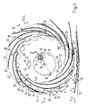
- the device shown in FIGS. 1 and 2 has three paddle wheels 14 of a printing machine which are seated on a common shaft 10 in a rotationally fixed manner and are spaced apart in the direction of the axis 12 of the shaft 10.
- the shaft 10 is freely rotatably mounted on stationary bearings 16 and driven in the direction of rotation U at the speed n1.
- Each paddle wheel has ten pockets 18, which are open to the rear in the direction of arrow U and are separated from one another by blades 20 and are closed off by a bottom 22 in their leading region.
- the orbit of the trailing free ends 20 'of the blades 20 is indicated by dash-dotted lines and designated 20 ⁇ (Fig. 1).
- An ejection arrangement 24 is provided in the area between each two paddle wheels 14. This has two ejection wheels 28, 30 driven in rotation around a dash-dot line of rotation 26 in the direction of arrow U.
- the speed n2 of the ejection wheels 28, 30 is half the speed n1 of the paddle wheels 14.
- the ejection wheels 28, 30 are disc-shaped, freely rotatably mounted on a common bearing arrangement 32 and encompass the shaft 10. The bearing arrangement 32 is further down in the 3 explained in more detail.
- the two ejection wheels 28, 30 are of the same size and are sawtooth-shaped on their circumference.
- the trailing flanks seen in the direction of rotation U form stops 34 for the printed products 36 shot into the pockets 18 for ejecting them from the paddle wheel 14.
- Each ejection wheel 28, 30 has ten stops 34 evenly distributed on the circumference, the two ejection wheels 28, 30 are rotated by half a division of the stops 34 against each other.
- the ejection arrangement 24 thus has twenty stops 34.
- leading flat flanks 38 seen in the direction of arrow U have a kink 40 in their central region, the respective leading, viewed in the radial direction inner flank part 38 'with the circular dash-dotted movement path 40' of the kink 40 enclosing a larger angle than the trailing flank part 38 ⁇ .
- Both ejection wheels 28, 30 have two slot-shaped passages 42 diametrically opposite one another, running centrally to the axis of rotation 26.
- a bolt-shaped fastening element 44 for releasably clamping the two ejection wheels 28, 30 runs through the corresponding passages 42 of both ejection wheels 28, 30.
- the fastening element 44 is, for example, a screw-nut connection.
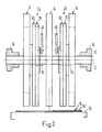
- a pinion 46 On the shaft 10, a pinion 46, indicated by a dot-dash line, also sits in a rotationally fixed manner for each ejection arrangement 24 and meshes with a corresponding internal toothing on the ejection wheel 30, which is not shown in FIGS. 1 and 2. 2, a linkage is designated in FIG. 2 by means of which the pivot position of the bearing arrangement 32 for the ejection wheels 28, 30 can be adjusted.
- a delivery conveyor 50 for example a belt conveyor, the conveying direction of which is denoted by F. This is directed in the same direction as the direction of rotation U of the paddle wheel 14 and the ejection wheels 28, 30.
- the conveying speed v1 corresponds to the peripheral speed v2 of the ejection wheels 28, 30 .
- Printed products 36 are pushed out of the pockets 18 by means of the ejection arrangement 24 and placed in scale formation S on the delivery conveyor 50, each printed product 36 resting like a roof tile on the printed product 36 leading in the conveying direction F.
- the distance between two stops 34 is indicated in FIG. 1 by the double arrow A and the distance between the folds 36 'of the printed products 36 designed in scale formation S is denoted by A'. Since the speeds v1 and v2 are the same, the distance A corresponds to the distance A '.
- FIG. 3 shows the bearing arrangement 32 for the two ejection wheels 28, 30 enlarged in a section along the line III-III of FIG. 1.
- the paddle wheel 14 and the pinion 46 are seated on the shaft 10 in a rotationally fixed manner.
- the bearing element is connected to the linkage 48 (see FIG. 2) and is adjustable in its pivoting position about the axis 12.
- the two ejection wheels 28, 30 are seated on the bearing element 52 and can be freely rotated about the axis of rotation 26 with respect thereto.
- the ejector wheel 30 adjacent to the pinion 46 has on the side facing the pinion 46 has a round recess 54 which is central to the axis of rotation 26 and has internal teeth 56. This meshes with a corresponding toothing of pinion 46.
- Fastening element 44 which is only indicated by dash-dotted lines in this figure, transmits the rotational movement of ejection wheel 30 to ejection wheel 28.
- the reduction between pinion 36 and ejection wheels 28, 30 is designed such that the two ejection wheels 28, 30 are driven at half the speed with respect to shaft 10.
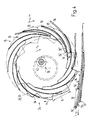
- the two ejection wheels 28, 30 can be rotated relative to one another by half a tooth pitch of an ejection wheel 28 or 30.
- the stops 34 of the two ejection wheels 28, 30 are aligned with one another.
- the ejection arrangement 24 has only ten ejection-effective stops 34. All parts shown in these two figures correspond to the parts described above and shown in FIGS. 1 to 3. They are therefore only mentioned again to the extent that this is necessary for an understanding of FIGS. 4 and 5.
- the paddle wheels 14, which are non-rotatably seated on the shaft 10, of which only one is visible, are driven to rotate in the direction of rotation U at the speed n1.
- the two aligned ejection wheels 28, 30 rotate in the direction of arrow U around the schematically indicated axis of rotation 26 at the speed n2, which is half the speed n1 of the paddle wheel 14. This has the consequence that two pockets 18 each have a common stop 34 is assigned.
- the scale formation S laid out on the delivery conveyor 50 has two congruent portions printed products 36 placed one on top of the other, which, as seen in the direction of conveyance F, each resemble roof tiles on the preceding pair of printed products 36.
- the conveying speed v1 of the delivery conveyor 50 corresponds to the peripheral speed v2 of the ejection wheels 28, 30.
- the distance B designated between two successive stops 34 corresponds to the distance B 'between the folds 36' leading in the direction of conveyance F 'of the printed products 36 arranged in scale formation S .
- the device shown in FIGS. 1 to 5 for laying out printed products 36 works in the operating mode shown in FIG. 1 as follows: In each pocket 18 of the paddle wheel 14, a printed product 36 with its fold 36 'is inserted in a known manner from above. shot in advance and comes with his fold 36 'on the bottom 22 of the pocket 18 in question. In the course of the further rotation of the paddle wheel 14, the printed product 36 runs with its fold 36 'due to the different speed between the bottom 22 and the stop 34 on a stop 34 of a paddle wheel 28 or 30 and is braked to the speed of the stop 34.
- the printed product 36 is clamped and held in the area of the fold 36 'between the pocket 18, seen in the radial direction, against the outwardly bounding blade 20 and a flatter flank part 38enteil of the other ejection wheel 30 and 28, respectively.
- the printing product in question 36 is displaced in the pocket 18 against the direction of the arrow U in accordance with the relative speed between the paddle wheel 14 and the ejection wheels 28, 30.
- the printed product 36 with its rear area seen in the direction of rotation U on the delivery conveyor 50 or the last printed product 36 placed thereon to the system and is finally released in the area of the fold 36 'from the paddle wheel 14 by the free end 20' of the blade 20 in question passes the stop 34.
- the blades 20 and flank parts 38 ⁇ are each at an acute angle to one another in the area in which the relevant stops 34 have an ejection effect and thus hold the corresponding printed products 36 in a wedge shape.
- the device shown in FIGS. 1 to 5 operates as follows in an operating mode according to FIGS. 4 and 5:
- the ejection arrangement 24 now has the same number of ejection stops 34 as the paddle wheel 14, pockets 18, the ejection wheels 28, 30 with respect to the paddle wheel 14 revolve at half speed n2.
- each stop 34 is responsible for ejecting two printed products 36 shot into adjacent pockets 18.
- the printed product 36 shot into the pocket 18 leading in the direction of the arrow U comes to rest on the floor 22 in question and, owing to the relative speed between the floor 22 and the stop 34 in question, hits it, is braked and, in the pocket 18, counter to the direction of the arrow U, pushed backwards.
- the printed product 36 shot into the next trailing pocket 18 as seen in the direction of the arrow U also comes into contact with the relevant floor 22 and runs onto the same stop 34 as the printed product 36 shot into the leading pocket 18.
- the printed product 36 shot into the rear pocket is clamped and held between the pocket 18 in question in the radial direction toward the outside delimiting blade 20 and the flank part 38 '. So there are two printed products 36 with their fold 36 'on the same stop 34.
- the printed product 36 arranged in the respective preceding outer pocket 18 is first ejected from the pocket 18 and released, this being placed on the delivery conveyor 50 with a distance B 'in relation to the printed products 36 already laid out in scale formation S (cf. Fig. 4).
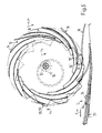
- the device shown in FIGS. 6 to 11 in a view and partially in a simplified manner and shown in FIG. 12 in a side view in the direction of the arrow XII in FIG. 6 has three, non-rotatably mounted on a shaft 70 in the direction of the axis 72 of the shaft 70 Paddle wheels 74 on.
- Figures 6 to 11 are the Paddle wheels 74 only partially shown.
- the delivery device is described in detail with reference to FIGS. 6 and 12; in Figures 7 to 11 only those reference numerals are given which are necessary for understanding.
- the shaft 70 is freely rotatably mounted in fixed bearings 76 and driven in the direction of rotation U at the speed n1.
- Each paddle wheel 74 has ten pockets 78, which are open towards the rear in the direction of rotation U and are defined by blades 80 in the radial direction and are delimited by a base 82 in their leading end.
- the rear free end of the blades 80 is designated 80 '(Fig. 6).
- An ejection arrangement designated by 84 each has a first ejection wheel 88 driven between the blade wheels 74 and rotating around the axis of rotation 86 (cf. in particular FIG. 12).
- the first ejection wheel 88 is designed in the shape of a disk ring and is freely rotatably mounted on a bearing arrangement 92 indicated by the dashed line in FIG. 12.
- the bearing arrangement 92 is of exactly the same design as the bearing arrangement 32 shown in FIG.
- the first ejection wheel 88 in the region of the bearing arrangement 92 being of the same design as the ejection wheel 30 according to FIG. 3.
- the first ejection wheel 88 is Via a pinion which is seated in a rotationally fixed manner on the shaft 70 and which meshes with an internal toothing on the first ejection wheel 88, is driven at a speed n2 which is half the speed n1 of the paddle wheel 74.
- the first ejector wheel 88 is sawtooth-shaped on its circumference, the twenty steep flanks trailing in the direction of rotation U being inserted as stops 94 for the pockets 78 of the paddle wheels 74 shoot printed products 96 serve.
- the flat flanks leading in the direction of arrow U with respect to the stops 94 are designated 98.
- the eccentric bearing arrangement 92 can be adjusted in its rotational position with respect to the axis 72 by means of a linkage 100 shown in FIG. 12, in order to hold printed products 96 of different thicknesses between the blades 80 and the flanks 90 in a known manner.
- the ejection arrangement 84 has a second ejection wheel 102 in the area between the shaft 70 and the radial end area of the first ejection wheel 88, as seen in the direction of the axis 72, outside the two outer vane wheels 74. As indicated by dash-dotted lines in FIG. 12, it would also be conceivable for the two second ejection wheels 102 or two additional second ejection wheels to be provided in the region between the first ejection wheels 88 and the central paddle wheel 74.
- the second ejection wheels 102 are freely rotatably mounted on a holder 104, which is only schematically indicated in FIG.
- the drive element 106 is preferably a chain drive, which in each case operatively connects the second ejection wheel 102 to the shaft 70 with a reduction ratio of 2: 1.
- the second ejector wheel 102 is sawtooth-shaped on its circumference, the steep, trailing flanks seen in the direction of rotation U being formed as stops 108 for the leading folds 96 'of the printed products 96.
- the number of stops 108 corresponds to the number of pockets 78 of each paddle wheel 74. Since the speed n3 of the second ejection wheel 102 is now half the speed n1 of the paddle wheels 74, a single stop 108 of the second ejection wheel 102 hits two pockets 78.
- the second ejection wheels 102 can be brought from the area of action on the printed products 96 by means of the holder 104, for example by pivoting in the direction of arrow B about the axis 72. By pivoting back against the direction of the arrow B into the position shown in the figures, the second ejector wheel 102 is again effective for ejection.
- a delivery conveyor 110 for example a belt conveyor, which is driven in the conveying direction F is provided below the paddle wheels 74 and the ejection arrangement 84.
- the conveying speed v1 of the delivery conveyor 110 corresponds to the peripheral speed v2 of the second ejection wheel 102.
- the delivery conveyor 110 is driven at a conveyor speed v1 which corresponds to the peripheral speed v3 corresponds to the first ejection wheel 88.
- a guide element 114 runs for the open trailing edges of the printed products 96 denoted 96 ⁇ , the fold 96 '.
- the printed products 96 placed thereon lie on the delivery conveyor 110 in a shingled formation S, two respective printed products 96 lying congruently one above the other lying on the leading pair of printed products 96 in the manner of roof tiles.
- the distance C 'between the leading folds 96' of two adjacent pairs of printed products 96 corresponds to the distance C between the stops 108 of the second ejection wheel 102.
- the printed products 96 if the second ejection wheel 102 is pivoted out of the area affected by the printed products 96, is deposited in a scale formation S on the delivery conveyor 110, in which each printed product 96 rests on the leading one in the manner of a roof tile.
- the distance between the folds 96 'of the printed products 96 deposited in scale formation corresponds to the distance C ⁇ between the stops 94 of the first ejection wheel 88.
- the second ejection wheel 102 is, for example, approximately half the diameter of the first ejection wheel 88 and also has half as many stops 108 as the first ejection wheel 88 has stops 94. Therefore, the distance C corresponds to the distance C ⁇ . This means that with each scale formation S formed, the distance between the folds 96 'always remains the same, un depending on whether each print product 96 is now placed on the leading pair of roof tiles or whether two printed products 96 'are stacked on top of each other on the leading pair of printed products 96.
- FIGS. 6 and 12 illustrate the functioning of the embodiment of the delivery device shown in FIGS. 6 and 12 for six different phases of a working cycle.
- a printed product 96 with its fold 96 ' is shot in advance in each pocket 78.
- the fold 96 ' comes to rest on the floor 82, whereby the printed product 96 is braked to the speed of the floor 82.
- the printed product 96 runs onto a stop 94 as a result of the relative speed between the base 82 and the stops 94 of the first ejection wheel 88.
- the printed product 96 is clamped in the area of the fold 96 'by the flank 98 in question and the pocket 78 in the radial direction towards the outside delimiting blade 80 and is gradually ejected from the pocket 78 against the direction of rotation U.
- the trailing edge 96 ⁇ comes into contact with the guide element 114.
- the printed product 96 bumps against a stop 108 as a result of the relative speed between the stops 94 of the first ejection wheel 88 and the stops 108 of the second ejection wheel 102, as shown in FIG. 7.
- the printed product 96 is at the relative speed between the Paddle wheels 74 and the relevant stop 108 pushed out of the pocket 78, as shown in FIG. 7.
- the trailing edge 96 ⁇ still slides along the guide element 114. Shortly thereafter, the relevant blade 80 runs away from the fold 96 ', whereby the printed product 96 is deposited on the scale formation S.
- next trailing printed product 96 seen in the direction of the arrow U is also held in the region of the fold 96 'between the blade 80 and the flank 98 of the first ejection wheel 88 in question and is in contact with the stop 94, as a result of which the relative speed between the first ejection wheel 88 and the paddle wheels 74 is pushed out of the pocket 78 (FIGS. 9 and 10).
- the printed product 96 to be deposited runs with its fold 96 'onto the same stop 108 of the second ejection wheel 102, against which the previously stored printed product 96 has already come into contact (FIG. 11). This comes with the area of its fold 96 'in the pocket 78 held print product 96 with its trailing edge 96 ⁇ to lie exactly over the trailing edge 96 ⁇ of the previously stored printed product 96. Shortly thereafter, the fold 96 'is released due to the relative speed between the paddle wheels 74 and the stop 108 of the second ejection wheel 102, whereby the printed product 96 comes to lie congruently on the previously stored printed product 96. It should be noted that each printed product 96 comes to lie in the same way between the relevant blade 80 and the corresponding flank 98 of the first ejection wheel 88 and is held by it.
- the delivery device By pivoting the second ejection wheel 102 in the direction of arrow B (FIG. 6) from the area of action on the printed products 96, the delivery device works exactly the same as the device known, for example, from EP-PS 0 059 873 and US-PS 4,434,979.
- the delivery conveyor 110 is now driven in accordance with the peripheral speed v3 of the first ejection wheel 88.
- Each in the feed area 112 in a pocket 78 of the paddle wheels 74 shot printed product 96 comes with its fold 96 'on the floor 82 to the system.
- the printed product 96 runs onto this stop 94.
- the printed product 96 is held in the area of its leading fold 96 'by the flank 98 and the blade 80.
- the printed product 96 is pushed out of the pocket 78 counter to the direction of rotation U, the trailing edge 96 ⁇ of the printed product 96 coming into contact with the guide element 114 and along this slides to the delivery conveyor 110.
- the leading fold 96 'now does not run onto a stop 108 of the second ejector wheel 102, but is ejected from the pocket 78 and released by the first ejector wheel 88.
- each printed product 96 is placed on the leading printed product 96 like a roof tile.
- the distance between the folds 96 'of the stored printed products 96 corresponds in this case to the distance C ⁇ between the stops 94 of the first ejection wheel 88.
Landscapes
- Engineering & Computer Science (AREA)
- Mechanical Engineering (AREA)
- Discharge By Other Means (AREA)
- Handling Of Cut Paper (AREA)
- Treatment Of Fiber Materials (AREA)
Abstract
Die Ausstossanordnung (24) weist zwei Ausstossräder (28, 30) auf, die an ihrem Umfang sägezahnförmig ausgebildet sind. Die Ausstossräder (28, 30) sind aus einer Lage, in welcher sie um eine halbe Zahnteilung gegeneinander verdreht sind, in eine Lage verschwenkbar, in welcher die Anschläge (34) beider Ausstossräder (28, 30) aufeinander ausgerichtet sind. Wenn die Ausstossräder (28, 30) um eine halbe Zahnteilung gegeneinander versetzt sind, läuft jedes in eine Tasche (18) des Schaufelrades (14) eingeschossene Druckereiprodukt (36) auf einen Anschlag (34) auf und wird von diesem infolge der unterschiedlichen Drehzahlen (n2, n1) des Schaufelrades (14) und der Ausstossräder (28, 30) aus der Tasche (18) ausgestossen und in Schuppenformation (S) auf den Auslegeförderer (50) abgelegt. Sind hingegen die Anschläge (34) beider Ausstossräder (28, 30) aufeinander ausgerichtet, so kommen jeweils an einem Anschlag (34) die Druckereiprodukte (36) zweier aufeinanderfolgender Taschen (18) zur Anlage, wodurch die beiden Druckereiprodukte (36) mit ihrem Falz (96') aufeinander ausgerichtet aus den Taschen (18) gestossen werden. Es wird damit eine Schuppenformation (S) gebildet, in welcher jeweils zwei Druckereiprodukte (36) deckungsgleich übereinanderliegend dachziegelartig auf dem vorauslaufenden Druckereiprodukten (36) aufliegen.The ejection arrangement (24) has two ejection wheels (28, 30) which are sawtooth-shaped on their circumference. The ejection wheels (28, 30) can be pivoted from a position in which they are rotated against each other by half a tooth pitch into a position in which the stops (34) of both ejection wheels (28, 30) are aligned with one another. If the ejection wheels (28, 30) are offset from each other by half a tooth pitch, each printed product (36) shot into a pocket (18) of the paddle wheel (14) runs up against a stop (34) and is driven by it as a result of the different speeds ( n2, n1) of the paddle wheel (14) and the ejection wheels (28, 30) are ejected from the pocket (18) and placed on the delivery conveyor (50) in scale formation (S). If, on the other hand, the stops (34) of both ejection wheels (28, 30) are aligned with one another, the printed products (36) of two successive pockets (18) come to rest against one stop (34), as a result of which the two printed products (36) with their fold (96 ') aligned with each other are pushed out of the pockets (18). A scale formation (S) is thus formed, in each of which two printed products (36) lie congruently one above the other in the manner of roof tiles on the preceding printed products (36).
Description
Die vorliegende Erfindung betrifft eine Vorrichtung zum Auslegen von insbesondere gefalteten Druckereiprodukten gemäss dem Oberbegriff des Ansprüches 1.The present invention relates to a device for laying out, in particular, folded printed products according to the preamble of
Eine solche Vorrichtung ist aus der EP-PS 0 059 873 bzw. der entsprechenden US-PS 4,434,979, bekannt. Diese weist ein scheibenringförmig ausgebildetes, bezüglich des Schaufelrades exzentrisch gelagertes Ausstossrad auf, das die Welle des Schaufelrades umgreift. Am Umfang des Ausstossrades verteilt sind doppelt soviele Anschläge vorgesehen, wie das Schaufelrad Taschen aufweist. Das Ausstossrad ist bezüglich des Schaufelrades mit halber Drehzahl angetrieben, so dass jeder Tasche zum Ausstossen der in die Taschen hineingeschossenen Druckereiprodukte jeweils ein Anschlag zugeordnet ist. Unterhalb des Schaufelrades ist ein Auslegeförderer vorgesehen, der mit einer Geschwindigkeit angetrieben ist, die der Umfangsgeschwindigkeit der Anschläge entspricht. Jedes in eine Tasche des Schaufelrades eingeschossene Druckereiprodukt läuft zunächst infolge der Relativgeschwindigkeit zwischen den Anschlägen und den Taschen auf den betreffenden Anschlag auf und wird im Zuge der Weiterdrehung des Schaufelrades und des Ausstossrades aus der Tasche ausgestossen und mit einem Abstand, welcher dem Abstand zwischen den Anschlägen entspricht, in Schuppenformation auf den Auslegeförderer abgelegt.Such a device is known from EP-PS 0 059 873 or the corresponding US-PS 4,434,979. This has a disk-shaped ejector wheel which is eccentrically mounted with respect to the impeller and which engages around the shaft of the impeller. Distributed around the circumference of the ejection wheel are twice as many stops as the paddle wheel has pockets. The ejection wheel is driven at half the speed of the paddle wheel, so that each pocket is assigned a stop for ejecting the printed products shot into the pockets. A delivery conveyor is provided below the paddle wheel, which is driven at a speed which corresponds to the peripheral speed of the stops. Each printed product shot into a pocket of the paddle wheel initially runs onto the relevant stop as a result of the relative speed between the stops and the pockets and is expelled from the pocket in the course of the further rotation of the paddle wheel and the ejection wheel and at a distance which is the distance between the stops corresponds, deposited in scale formation on the delivery conveyor.
Eine weitere Vorrichtung zum Auslegen von Druckereiprodukten aus einem drehend angetriebenen Schaufelrad ist aus der US-PS 2,172,364 bekannt. Das Ausstossrad dieser Vorrichtung ist zwischen der Welle und den Taschen des Schaufelrades drehbar gelagert und mit gleicher Drehzahl und Drehrichtung angetrieben wie das Schaufelrad. Die Anzahl Anschläge des Ausstossrades entspricht der Anzahl Taschen des Schaufelrades. Jedes in eine Tasche eingeschossene Druckereiprodukt läuft auf einen Anschlag auf und wird infolge der kleineren Umfangsgeschwindigkeit des Ausstossrades bezüglich des Schaufelrades aus der Tasche ausgestossen und in Schuppenformation auf einen unterhalb des Schaufelrades angeordneten Auslegeförderer abgelegt.Another device for laying out printed products from a rotatably driven paddle wheel is known from US Pat. No. 2,172,364. The ejection wheel of this device is rotatably mounted between the shaft and the pockets of the paddle wheel and driven at the same speed and direction of rotation as the paddle wheel. The number of stops on the ejector wheel corresponds to the number of pockets on the paddle wheel. Each printed product shot into a pocket comes up against a stop and is ejected from the pocket as a result of the smaller peripheral speed of the ejection wheel with respect to the paddle wheel and placed in a scale formation on a delivery conveyor arranged below the paddle wheel.
Für die Weiterverarbeitung der Druckereiprodukte kann es von Vorteil sein, wenn in einer Schuppenformation jeweils mindestens zwei Druckereiprodukte deckungsgleich übereinanderliegend, dachziegelartig auf den vorauslaufenden Druckereiprodukten aufliegen. Eine Vorrichtung zum Bilden von Stapeln aus aus einem Schaufelrad ausgestossenen Signaturbögen und Wegfördern dieser Stapel in Schuppenformation ist aus der EP-OS 0 179 992 bekannt. Diese weist einen ortsfesten Anschlag auf, an welchem die Signaturbögen anstossen und so, in Umlaufrichtung des Schaufelrades gesehen, zum Stillstand gebracht werden. Die so aus den Schaufeln des Schaufelrades ausgestossenen Signaturbögen schweben im freien Fall auf eine Halteeinrichtung bzw. die bereits darauf abgelegten Signaturbögen. Die Halteeinrichtung hält jeweils den untersten Signaturbogen eines Stapels gegen die Reibungsmitnahme durch den vorgängig fertig gebildeten, wegzufördernden Stapel zurück. Der Auslegeförderer und das Schaufelrad sind derart synchronisiert, dass der Auslegeförderer jeweils einen Stapel wegfördert, sobald dieser die gewünschte Anzahl Signaturbögen aufweist. Bei dieser bekannten Vorrichtung werden die Signaturbögen am Anschlag sehr stark abgebremst, was zu Beschädigungen derselben führen kann.For the further processing of the printed products, it can be advantageous if in a scale formation at least two printed products each lie congruently one above the other, roof-tile-like on the preceding printed products. A device for forming stacks from signature sheets ejected from a paddle wheel and conveying away these stacks in scale formation is known from EP-OS 0 179 992. This has a stationary stop, against which the signature sheets abut and are brought to a standstill, as seen in the direction of rotation of the impeller. The signature sheets ejected from the blades of the paddle wheel float in free fall onto a holding device or the signature sheets already placed thereon. The holding device in each case holds back the bottom signature sheet of a stack against the frictional entrainment by the stack which has previously been formed and is to be transported away. The Delivery conveyor and the paddle wheel are synchronized in such a way that the delivery conveyor in each case conveys away a stack as soon as it has the desired number of signature sheets. In this known device, the signature sheets are braked very strongly at the stop, which can damage them.
Es ist eine Aufgabe der vorliegenden Erfindung, eine gattungsgemässe Vorrichtung zu schaffen, mittels welcher unter schonender Behandlung der Druckereiprodukte die wahlweise Bildung unterschiedlicher Schuppenformationen möglich ist.It is an object of the present invention to provide a generic device by means of which the selective formation of different scale formations is possible with gentle treatment of the printed products.
Diese Aufgabe wird durch die Merkmale des kennzeichnenden Teiles des Anspruches 1 gelöst.This object is achieved by the features of the characterizing part of
Durch die Veränderung der Anzahl der ausstosswirksamen Anschläge kann nun wahlweise jeder Tasche des Schaufelrades ein Anschlag oder können jeweils zwei oder mehr Taschen ein gemeinsamer Anschlag zugeordnet werden. Falls ein Anschlag auf das Druckereiprodukt in einer einzigen Tasche einwirkt, werden die Druckereiprodukte einzeln ausgelegt, wobei der Abstand zwischen den Vorlaufkanten der Druckereiprodukte dem Abstand zwischen den Anschlägen entspricht. Durch das Aendern der Anzahl ausstosswirksamer Anschläge wird nun ermöglicht, dass die in zwei oder mehr Taschen angeordneten Druckereiprodukte auf einen gemeinsamen Anschlag auflaufen und von diesem übereinanderliegend aus dem Schaufelrad ausgestossen werden. Die gewünschte Formation wird somit direkt beim Auslegen der Druckereiprodukte ohne Hilfe von ausserhalb des Schaufelrades und der Ausstossanordnung vorgesehenen Mitteln gebildet.By changing the number of stops with effective ejection, either one pocket of the paddle wheel can now be assigned a stop or two or more pockets can be assigned a common stop. If a stop acts on the printed product in a single pocket, the printed products are laid out individually, the distance between the leading edges of the printed products corresponding to the distance between the stops. By changing the number of ejection-effective stops, it is now possible for the printed products arranged in two or more pockets to run onto a common stop and to be ejected from the paddle wheel lying one above the other. The desired formation is thus formed directly when the printed products are laid out without the aid of means provided outside the paddle wheel and the ejection arrangement.
In einer besonders bevorzugten und einfachen Ausbildungsform ist die Anzahl der ausstosswirksamen Anschläge halbierbar. Dadurch ist es möglich, vom Auslegen in einer Schuppenformation, in welcher jedes Druckereiprodukt einzeln aus dem Schaufelrad ausgestrossen wird, in eine Schuppenformation, in welcher jeweils zwei Druckereiprodukte gemeinsam und übereinanderliegend ausgestossen werden, umzuschalten, ohne das Drehzahlverhältnis zwischen dem Schaufelrad und der Ausstossanordnung zu ändern.In a particularly preferred and simple form of training, the number of ejector-effective stops can be halved. This makes it possible to switch from laying out in a shed formation, in which each printed product is ejected individually from the paddle wheel, into a shed formation, in which two printed products are ejected together and one above the other, without changing the speed ratio between the paddle wheel and the ejection arrangement .
Eine besonders bevorzugte Ausbildungsform der erfindungsgemässen Vorrichtung ist im Anspruch 3 angegeben. Die Ausstossanordnung weist zwei Ausstossräder auf, die je die gleiche Anzahl Anschläge aufweisen. Durch Aufeinander-Ausrichten der Anschläge beider Ausstossräder bzw. durch Gegeneinander-Verdrehen der beider Anschlagräder um eine halbe Teilung der Anschläge ist die Anzahl der ausstosswirksamen Anschläge halbier- bzw. verdoppelbar.A particularly preferred embodiment of the device according to the invention is specified in claim 3. The ejection arrangement has two ejection wheels, each of which has the same number of stops. By aligning the stops of the two ejection wheels towards one another or by rotating the two stop wheels against one another by half a division of the stops, the number of stops effective at ejection can be halved or doubled.
Bei einer weiteren ebenfalls besonders bevorzugten Ausbildungsform gemäss Anspruch 7 wird jedes Druckereiprodukt von einem ersten Ausstossrad und der betreffenden Schaufel auf gleiche optimale Art und Weise abgebremst und zu den Anschlägen eines zweiten Ausstossrades geführt. Ueberdies ist gemäss dieser Ausbildungsform ein Nachrüsten von bekannten Vorrichtungen, beispielsweise einer Vorrichtung gemäss der EP-PS 0 059 873 bzw. der entsprechenden US-PS 4,434,979 möglich, ohne das Schaufelrad bzw. das Ausstossrad zu ändern.In a further likewise particularly preferred embodiment according to claim 7, each printed product is braked in the same optimal manner by a first ejection wheel and the relevant bucket and guided to the stops of a second ejection wheel. In addition, according to this embodiment, retrofitting of known devices, for example a device according to EP-PS 0 059 873 or the corresponding US-PS 4,434,979, is possible without changing the paddle wheel or the ejection wheel.
In einer weiteren bevorzugten Ausbildungsform der erfindungsgemässen Vorrichtung ist unterhalb des Schaufelrades ein Auslegeförderer gemäss Anspruch 9 vorgesehen. Die Druckereiprodukte werden im wesentlichen mit derselben Geschwindigkeit, in Förderrichtung des Auslegeförderers gesehen, aus dem Schaufelrad ausgestossen und auf den Auslegeförderer abgelegt, wie sie von diesem wegtransportiert werden. Es besteht somit kaum eine Relativgeschwindigkeit zwischen dem Bandförderer und den darauf abzulegenden Druckereiprodukten, was zu der Bildung einer besonders genauen Schuppenformation führt.In a further preferred embodiment of the device according to the invention, a delivery conveyor according to claim 9 is provided below the paddle wheel. The printed products are ejected from the paddle wheel and deposited on the delivery conveyor at essentially the same speed, seen in the conveying direction of the delivery conveyor, and placed on the delivery conveyor as they are transported away from the latter. There is therefore hardly any relative speed between the belt conveyor and the printed products to be placed on it, which leads to the formation of a particularly precise scale formation.
Weitere bevorzugte Ausbildungsformen sind in den weiteren abhängigen Ansprüchen angegeben.Further preferred forms of training are specified in the further dependent claims.
Die Erfindung wird nun anhand von zwei in der Zeichnung dargestellten Ausbildungsformen näher erläutert. Es zeigen rein schematisch:
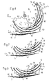
- Fig. 1 In Ansicht eine erste Ausbildungsform der Auslegevorrichtung,
- Fig. 2 Eine Seitenansicht der Auslegevorrichtung in Richtung des Pfeiles II der Fig. 1,
- Fig. 3 In vergrösserter Darstellung einen Schnitt entlang der Linie III - III der Fig. 1,
- Fig. 4 und 5 In Seitenansicht die Vorrichtung gemäss Fig. 1 beim Aufeinanderablegen von zwei Druckereiprodukten zu verschiedenen Phasen eines Arbeitszyklus,
- Fig. 6 bis 11 In Ansicht vereinfacht eine weitere Ausbildungsform der Auslegevorrichtung zu sechs verschiedenen Zeitpunkten eines Arbeitszyklus, und
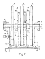
- Fig. 12 Eine Seitenansicht der Auslegevorrichtung in Richtung des Pfeiles XII der Fig. 6.
- 1 is a view of a first embodiment of the delivery device,
- 2 is a side view of the delivery device in the direction of arrow II of FIG. 1,
- 3 is an enlarged view of a section along the line III - III of FIG. 1,
- 4 and 5 in side view of the device of FIG. 1 when two printed products are placed on top of each other at different phases of a work cycle,
- 6 to 11 in view simplifies a further embodiment of the delivery device at six different points in time of a working cycle, and
- 12 is a side view of the delivery device in the direction of arrow XII of FIG. 6th
Die in den Figuren 1 und 2 dargestellte Vorrichtung weist drei auf einer gemeinsamen Welle 10 drehfest sitzende, in Richtung der Achse 12 der Welle 10 voneinander beabstandete Schaufelräder 14 einer Druckereimaschine auf. Die Welle 10 ist an ortsfesten Lagern 16 frei drehbar gelagert und in Drehrichtung U mit der Drehzahl n1 angetrieben. Jedes Schaufelrad weist zehn, in Pfeilrichtung U gesehen nach hinten offene Taschen 18 auf, die durch Schaufeln 20 voneinander getrennt und in ihrem vorlaufenden Bereich durch einen Boden 22 abgeschlossen sind. Die Umlaufbahn der nachlaufenden freien Enden 20′ der Schaufeln 20 ist strichpunktiert angegeben und mit 20˝ bezeichnet (Fig. 1).The device shown in FIGS. 1 and 2 has three
Im Bereich zwischen jeweils zwei Schaufelrädern 14 ist eine Ausstossanordnung 24 vorgesehen. Diese weist zwei um eine strichpunktiert angedeutete Drehachse 26 in Pfeilrichtung U umdrehend angetriebene Ausstossräder 28, 30 auf. Die Drehzahl n2 der Ausstossräder 28, 30 ist halb so gross wie die Drehzahl n1 der Schaufelräder 14. Die Ausstossräder 28, 30 sind scheibenringförmig ausgebildet, auf einer gemeinsamen Lageranordnung 32 frei drehbar gelagert und umgreifen die Welle 10. Die Lageranordnung 32 ist weiter unten im Zusammenhang mit Fig. 3 näher erläutert.An
Die beiden Ausstossräder 28, 30 sind gleich gross und an ihrem Umfang sägezahnförmig ausgebildet. Die in Umlaufrichtung U gesehen nachlaufenden steilen Flanken bilden Anschläge 34 für die in die Taschen 18 eingeschossenen Druckereiprodukte 36 zum Ausstossen derselben aus dem Schaufelrad 14. Jedes Ausstossrad 28, 30 weist zehn am Umfang gleichmässig verteilte Anschläge 34 auf, wobei die beiden Ausstossräder 28, 30 um eine halbe Teilung der Anschläge 34 gegeneinander verdreht sind. Die Ausstossanordnung 24 weist somit zwanzig Anschläge 34 auf. Die in Pfeilrichtung U gesehen vorlaufenden flachen Flanken 38 weisen in ihrem Mittelbereich einen Knick 40 auf, wobei der jeweils vorauslaufende, in radialer Richtung gesehen innere Flankenteil 38′ mit der kreisförmigen strichpunktiert angedeuteten Bewegungsbahn 40′ der Knicke 40 einen grösseren Winkel einschliesst als der nachlaufende Flankenteil 38˝.The two
Beide Ausstossräder 28, 30 weisen zwei einander diametral gegenüberliegende, zentrisch zur Drehachse 26 verlaufende, langlochförmige Durchlässe 42 auf. Durch die einander entsprechenden Durchlässe 42 beider Ausstossräder 28, 30 verläuft ein bolzenförmiges Befestigungselement 44 zum lösbaren Gegeneinanderspannen der beiden Ausstossräder 28, 30. Beim Befestigungselement 44 handelt es sich beispielsweise um eine Schrauben-Mutter Verbindung.Both
Auf der Welle 10 sitzt weiter drehfest pro Ausstossanordnung 24 ein strichpunktiert angedeutetes Ritzel 46, das mit einer entsprechenden, in den Figuren 1 und 2 nicht gezeigten Innenverzahnung am Ausstossrad 30 kämmt. Mit 48 ist in der Fig. 2 ein Gestänge bezeichnet, mittels welchem die Schwenklage der Lageranordnung 32 für die Ausstossräder 28, 30 einstellbar ist.On the
Unterhalb des Schaufelrades 14 ist ein Auslegeförderer 50, beispielsweise ein Bandförderer, vorgesehen, dessen Förderrichtung mit F bezeichnet ist. Diese ist gleich gerichtet wie die Umlaufrichtung U des Schaufelrades 14 und der Ausstossräder 28, 30. Die Fördergeschwindigkeit v1 entspricht der Umfangsgeschwindigkeit v2 der Ausstossräder 28, 30. Die mit ihrem in Pfeilrichtung U gesehen vorlaufenden Falz 36′ in die Taschen 18 des Schaufelrades 14 eingeschossenen Druckereiprodukte 36 werden mittels der Ausstossanordnung 24 aus den Taschen 18 gestossen und in Schuppenformation S auf den Auslegeförderer 50 abgelegt, wobei jedes Druckereiprodukt 36 dachziegelartig auf dem in Förderrichtung F gesehen vorauslaufenden Druckereiprodukt 36 aufliegt. Der Abstand zwischen zwei Anschlägen 34 ist in der Figur 1 mit dem Doppelpfeil A angedeutet und der Abstand zwischen den Falzen 36′ der in Schuppenformation S ausgelegten Druckereiprodukte 36 mit A′ bezeichnet. Da die Geschwindigkeiten v1 und v2 gleich sind, entspricht der Abstand A dem Abstand A′.Below the
Fig. 3 zeigt die Lageranordnung 32 für die beiden Ausstossräder 28, 30 in einem Schnitt entlang der Linie III-III der Fig. 1 vergrössert. Das Schaufelrad 14 und das Ritzel 46 sitzen drehfest auf der Welle 10. Auf der dem Schaufelrad 14 abgewandten Seite des Ritzels 46 ist an der Welle 10 ein kreisscheibenförmiges Lagerelement 52 exzentrisch frei drehbar gelagert. Das Lagerelement ist mit dem Gestänge 48 (vgl. Fig. 2) verbunden und in seiner Schwenklage um die Achse 12 einstellbar. Auf dem Lagerelement 52 sitzen die beiden Ausstossräder 28, 30 und sind bezüglich diesem um die Drehachse 26 frei drehbar. Das dem Ritzel 46 benachbarte Ausstossrad 30 weist auf der dem Ritzel 46 zugewandten Seite eine runde, zur Drehachse 26 zentrische Ausnehmung 54 mit einer Innenverzahnung 56 auf. Diese kämmt mit einer entsprechenden Verzahnung des Ritzels 46. Durch das in dieser Figur nur strichpunktiert angedeutete Befestigungselement 44 wird die Drehbewegung des Ausstossrades 30 auf das Ausstossrad 28 übertragen. Die Untersetzung zwischen Ritzel 36 und Ausstossrädern 28, 30 ist derart ausgebildet, dass die beiden Ausstossräder 28, 30 mit bezüglich der Welle 10 halber Drehzahl angetrieben sind.FIG. 3 shows the bearing
Durch Lösen der Befestigungselemente 44 (vgl. Fig. 1) sind die beiden Ausstossräder 28, 30 um eine halbe Zahnteilung eines Ausstossrades 28 bzw. 30 gegeneinander verdrehbar. Wie dies in den Figuren 4 und 5 dargestellt ist, sind dabei die Anschläge 34 der beiden Ausstossräder 28, 30 aufeinander ausgerichtet. Die Ausstossanordnung 24 weist in diesem Fall nur noch zehn ausstosswirksame Anschläge 34 auf. Alle in diesen beiden Figuren gezeigten Teile entsprechen den weiter oben beschriebenen und in den Figuren 1 bis 3 gezeigten Teilen. Sie werden deshalb nur insofern nochmals erwähnt, als dies für das Verständnis der Figuren 4 und 5 notwendig ist. Die auf der Welle 10 drehfest sitzenden Schaufelräder 14, von welchen nur eines sichtbar ist, sind in Umlaufrichtung U mit der Drehzahl n1 drehend angetrieben. Die beiden aufeinander ausgerichteten Ausstossräder 28, 30 laufen in Pfeilrichtung U um die schematisch angedeutete Drehachse 26 mit der Drehzahl n2 um, die halb so gross ist wie die Drehzahl n1 des Schaufelrades 14. Dies hat zur Folge, dass jeweils zwei Taschen 18 ein gemeinsamer Anschlag 34 zugeordnet ist. Die auf den Auslegeförderer 50 ausgelegte Schuppenformation S weist jeweils zwei deckungsgleich aufeinander abgelegte Druckereiprodukte 36 auf, die in Förderrichtung F gesehen, jeweils dachziegelartig auf dem vorauslaufenden Paar Druckereiprodukte 36 aufliegen. Die Fördergeschwindigkeit v1 des Auslegeförderers 50 entspricht der Umfangsgeschwindigkeit v2 der Ausstossräder 28, 30. Der mit B bezeichnete Abstand zwischen zwei aufeinanderfolgenden Anschlägen 34 entspricht dem Abstand B′ zwischen den, in Förderrichtung F gesehen, vorauslaufenden Falzen 36′ der in Schuppenformation S angeordneten Druckereiprodukte 36.By loosening the fastening elements 44 (cf. FIG. 1), the two
Die in den Figuren 1 bis 5 dargestellte Vorrichtung zum Auslegen von Druckereiprodukten 36 arbeitet in der in der Fig. 1 gezeigten Betriebsart wie folgt: In jede Tasche 18 des Schaufelrades 14 wird in bekannter Art und Weise von oben ein Druckereiprodukt 36 mit seinem Falz 36′ voraus eingeschossen und kommt dabei mit seinem Falz 36′ auf dem Boden 22 der betreffenden Tasche 18 zur Anlage. Im Zuge der Weiterdrehung des Schaufelrades 14 läuft das Druckereiprodukt 36 mit seinem Falz 36′ infolge der unterschiedlichen Geschwindigkeit zwischen dem Boden 22 und dem Anschlag 34 auf einen Anschlag 34 des einen Schaufelrades 28 oder 30 auf und wird dabei auf die Geschwindigkeit des Anschlages 34 abgebremst. Gleichzeitig wird das Druckereiprodukt 36 im Bereich des Falzes 36′ zwischen der die Tasche 18, in radialer Richtung gesehen, gegen aussen begrenzenden Schaufel 20 und einem flacher verlaufenden Flankenteil 38˝ des anderen Ausstossrades 30 bzw. 28 eingeklemmt und gehalten. Im Zuge der Weiterdrehung wird das betreffende Druckereiprodukt 36 entsprechend der Relativgeschwindigkeit zwischen dem Schaufelrad 14 und den Ausstossrädern 28, 30 in der Tasche 18 entgegen der Pfeilrichtung U nach hinten verschoben. Dabei kommt das Druckereiprodukt 36 mit seinem in Umlaufrichtung U gesehen hinteren Bereich auf den Auslegeförderer 50 bzw. das letzte darauf abgelegte Druckereiprodukt 36 zur Anlage und wird schlussendlich im Bereich des Falzes 36′ vom Schaufelrad 14 freigegeben, indem das frei Ende 20′ der betreffenden Schaufel 20 am Anschlag 34 vorbeiläuft.The device shown in FIGS. 1 to 5 for laying out printed
Die Schaufeln 20 und Flankenteile 38˝ stehen jeweils im Bereich, in welchem die betreffenden Anschläge 34 ausstosswirksam sind, in einem spitzen Winkel zueinander und halten somit die entsprechenden Druckereiprodukte 36 keilförmig fest.The
Um eine saubere Abbremsung und ein sicheres Festhalten verschieden dicker Druckereiprodukte 36 zu gewährleisten, kann nun die Verdrehlage der Lageranordnung 32 mittels des Gestänges 48 eingestellt werden.In order to ensure a clean braking and secure holding of printed
Da die Fördergeschwindigkeit v1 des Auslegeförderers 50 der Umfangsgeschwindigkeit v2 der Ausstossräder 28, 30 entspricht, gibt es keine Relativverschiebung zwischen den bereits ausgelegten Druckereiprodukten 36 und dem nächsten auszulegenden Druckereiprodukt 36. Dies führt zu einer sauberen Schuppenformation mit konstantem Abstand A′. Gemäss Fig. 1 wird also jedes Druckereiprodukt 36 einzeln durch einen Anschlag 34 aus der betreffenden Tasche 18 ausgestossen.Since the conveying speed v1 of the
Die in den Figuren 1 bis 5 dargestellte Vorrichtung arbeitet bei einer Betriebsart gemäss den Figuren 4 und 5 wie folgt: Die Ausstossanordnung 24 weist nun gleich viele ausstosswirksame Anschläge 34 auf wie das Schaufelrad 14 Taschen 18, wobei die Ausstossräder 28, 30 bezüglich des Schaufelrades 14 mit halber Drehzahl n2 umlaufen. Dies hat zur Folge, dass jeder Anschlag 34 für das Ausstossen von zwei in benachbarte Taschen 18 eingeschossene Druckereiprodukte 36 verantwortlich ist. Das in die jeweils in Pfeilrichtung U vorlaufende Tasche 18 eingeschossene Druckereiprodukt 36 kommt auf dem betreffenden Boden 22 zur Anlage und läuft infolge der Relativgeschwindigkeit zwischen dem Boden 22 und dem betreffenden Anschlag 34 auf diesen auf, wird abgebremst und, in der Tasche 18 entgegen der Pfeilrichtung U, nach hinten gestossen. Das in Pfeilrichtung U gesehen in die nächste nachlaufende Tasche 18 eingeschossene Druckereiprodukt 36 kommt ebenfalls am betreffenden Boden 22 zur Anlage und läuft auf den gleichen Anschlag 34 wie das in die vorauslaufende Tasche 18 eingeschossene Druckereiprodukt 36 auf. Das in die hintere Tasche eingeschossene Druckereiprodukt 36 wird zwischen der die betreffende Tasche 18 in radialer Richtung gegen aussen begrenzenden Schaufel 20 und dem Flankenteil 38′ eingeklemmt und gehalten. Es liegen also zwei Druckereiprodukte 36 mit ihrem Falz 36′ an demselben Anschlag 34 an. Im Zuge der Weiterdrehung wird das in der jeweils vorauslaufenden, äusseren Tasche 18 angeordnete Druckereiprodukt 36 zuerst aus der Tasche 18 ausgestossen und freigegeben, wobei dieses gegenüber den bereits ausgelegten Druckereiprodukten 36 in Schuppenformation S mit einem Abstand B′ auf den Auslegeförderer 50 abgelegt wird (vgl. Fig. 4). Bei der Weiterdrehung des Schaufelrades 14 wird nun auch das in der nachlaufenden Tasche 18 angeordnete Druckereiprodukt 36 aus dem Schaufelrad 14 ausgestossen und freigegeben. Da die Fördergeschwindigkeit v1 des Auslegeförderers 50 gleich gross ist wie die Umfangsgeschwindigkeit v2 der Ausstossräder 28, 30, kommt nun dieses Druckereiprodukt 36 deckungsgleich über das bereits abgelegte Druckereiprodukt 36 zu liegen, wie dies in der Fig. 5 dargestellt ist. In gleicher Art und Weise werden nun die beiden nächsten Druckereiprodukte 36 dachziegelartig auf die bereits abgelegten Druckereiprodukte 36 ausgelegt.The device shown in FIGS. 1 to 5 operates as follows in an operating mode according to FIGS. 4 and 5: The
Es ist zu beachten, dass für die Umstellung von der einen Betriebsart auf die andere lediglich das Gegeneinander-Verdrehen der beiden Ausstossräder 28, 30 um eine halbe Teilung der Anschläge 34 notwendig ist. Weder eine Umstellung der Geschwindigkeitsverhältnisse zwischen dem Schaufelrad 14 und den Ausstossrädern 28, 30 noch eine Aenderung der Fördergeschwindigkeit v1 des Auslegeförderers 50 ist nötig. Einzig der Abstand A′ bzw. B′ zwischen den Falzen 36′ der Druckereiprodukte 36 verdoppelt bzw. halbiert sich. Bei einer Aenderung der Auslegegeschwindigkeit tritt somit weder eine Aenderung des Schuppenabstandes A′, B′ noch eine Phasenverschiebung zwischen der Schuppenformation S und dem Auslegeförderer 50 auf.It should be noted that for the changeover from one operating mode to the other it is only necessary to turn the two
Die in den Figuren 6 bis 11 in Ansicht und teilweise vereinfacht dargestellte und in Fig. 12 in Seitenansicht in Richtung des Pfeiles XII der Fig. 6 gezeigte Vorrichtung weist drei auf einer Welle 70 in Richtung der Achse 72 der Welle 70 voneinander beabstandete, drehfest sitzende Schaufelräder 74 auf. In den Figuren 6 bis 11 sind die Schaufelräder 74 nur teilweise gezeigt. Die Auslegevorrichtung wird anhand der Figuren 6 und 12 ausführlich beschrieben; in den Figuren 7 bis 11 sind nur jene Bezugszeichen angegeben, die für das Verständnis notwendig sind. Die Welle 70 ist in ortsfesten Lagern 76 frei drehbar gelagert und in Umlaufrichtung U mit der Drehzahl n1 angetrieben. Jedes Schaufelrad 74 weist zehn, in Umlaufrichtung U gesehen gegen hinten offene Taschen 78 auf, welche in radialer Richtung gesehen von Schaufeln 80 und in ihrem vorlaufenden Ende von einem Boden 82 begrenzt sind. Das hintere freie Ende der Schaufeln 80 ist mit 80′ bezeichnet (Fig. 6). Eine mit 84 bezeichnete Ausstossanordnung weist jeweils zwischen den Schaufelrädern 74 ein um die Drehachse 86 umlaufend angetriebenes erstes Ausstossrad 88 auf (vgl. insbesondere Fig. 12). Das erste Ausstossrad 88 ist scheibenringförmig ausgebildet und an einer in der Fig. 12 gestrichelt angedeuteten Lageranordnung 92 frei drehbar gelagert. Die Lageranordnung 92 ist genau gleich ausgebildet wie die in der Fig. 3 gezeigte und weiter oben ausführlich beschriebene Lageranordnung 32, wobei das erste Ausstossrad 88 im Bereich der Lageranordnung 92 gleich ausgebildet ist wie das Ausstossrad 30 gemäss Fig. 3. Das erste Ausstossrad 88 ist über ein auf der Welle 70 drehfest sitzendes Ritzel, welches mit einer Innenverzahnung am ersten Ausstossrad 88 kämmt, mit einer Drehzahl n2 angetrieben, die halb so gross ist wie die Drehzahl n1 des Schaufelrades 74.The device shown in FIGS. 6 to 11 in a view and partially in a simplified manner and shown in FIG. 12 in a side view in the direction of the arrow XII in FIG. 6 has three, non-rotatably mounted on a
Das erste Ausstossrad 88 ist an seinem Umfang sägezahnförmig ausgebildet, wobei die zwanzig, in Umlaufrichtung U gesehen, nachlaufenden steilen Flanken als Anschläge 94 für die in die Taschen 78 der Schaufelräder 74 einge schossenen Druckereiprodukte 96 dienen. Die flachen, bezüglich der Anschläge 94 in Pfeilrichtung U vorlaufenden Flanken sind mit 98 bezeichnet. Mittels eines in der Fig. 12 gezeigten Gestänges 100 ist die exzentrische Lageranordnung 92 in seiner Verdrehlage bezüglich der Achse 72 einstellbar, um in bekannter Art und Weise unterschiedlich dicke Druckereiprodukte 96 zwischen den Schaufeln 80 und den Flanken 90 zu halten.The
Die Ausstossanordnung 84 weist im Bereich zwischen der Welle 70 und dem unten liegenden radialen Endbereich des ersten Ausstossrades 88, in Richtung der Achse 72 gesehen, ausserhalb der beiden äusseren Schaufelräder 74 je ein zweites Ausstossrad 102 auf. Wie dies in der Fig. 12 strichpunktiert angegeben ist, wäre es auch denkbar, dass die beiden zweiten Ausstossräder 102 bzw. zwei zusätzliche zweite Ausstossräder im Bereich zwischen den ersten Austossrädern 88 und dem mittleren Schaufelrad 74 vorgesehen sind. Die zweiten Ausstossräder 102 sind an einer in der Fig. 12 nur schematisch angedeuteten Halterung 104 frei drehbar gelagert und mittels eines schematisch angedeuteten Antriebelementes 106 ebenfalls in Umlaufrichtung U mit der Drehzahl n3 antreibbar, wobei die Drehzahl n3 gleich der Drehzahl n2 des ersten Ausstossrades 88 ist. Dies bedeutet, dass die zweiten Ausstossräder 102 bezüglich der Schaufelräder 74 mit halber Drehzahl angetrieben sind. Beim Antriebselement 106 handelt es sich vorzugsweise um einen Kettentrieb, welcher jeweils das zweite Ausstossrad 102 mit einer Untersetzung von 2:1 mit der Welle 70 wirkverbindet.The
Das zweite Ausstossrad 102 ist an seinem Umfang sägezahnförmig ausgebildet, wobei die steilen, in Umlaufrichtung U gesehen nachlaufenden Flanken als Anschläge 108 für die vorauslaufenden Falze 96′ der Druckereiprodukte 96 ausgebildet sind. Die Anzahl der Anschläge 108 stimmt mit der Anzahl Taschen 78 jedes Schaufelrades 74 überein. Da nun die Drehzahl n3 des zweiten Ausstossrades 102 halb so gross ist wie die Drehzahl n1 der Schaufelräder 74 trifft jeweils auf zwei Taschen 78 ein einziger Anschlag 108 des zweiten Ausstossrades 102.The
Die zweiten Ausstossräder 102 sind mittels der Halterung 104 aus dem Einwirkbereich auf die Druckereiprodukte 96, beispielsweise durch Verschwenken in Pfeilrichtung B um die Achse 72, bringbar. Durch Zurückverschwenken entgegen Pfeilrichtung B in die in den Figuren gezeigte Stellung wird das zweite Ausstossrad 102 wiederum ausstosswirksam.The
Unterhalb der Schaufelräder 74 und der Ausstossanordnung 84 ist ein Auslegeförderer 110 vorgesehen, beispielsweise ein Bandförderer, welcher in Förderrichtung F angetrieben ist. Bei ausstosswirksamem zweiten Ausstossrad 102 entspricht die Fördergeschwindigkeit v1 des Auslegeförderers 110 der Umfangsgeschwindigkeit v2 des zweiten Ausstossrades 102. Ist hingegen das zweite Ausstossrad 102 aus dem Einwirkbereich auf die Druckereiprodukte 96 verschwenkt, so wird der Auslegeförderer 110 mit einer Fördergeschwindigkeit v1 angetrieben, die der Umlaufgeschwindigkeit v3 des ersten Ausstossrades 88 entspricht.A
Von einem Zuführbereich 112 der Druckereiprodukte 96 bis in den Bereich oberhalb des Auslegeförderers 110 verläuft ein Leitelement 114 für die mit 96˝ bezeichneten, dem Falz 96′ gegenüberliegenden offenen Nachlaufkanten der Druckereiprodukte 96.From a
Auf dem Auslegeförderer 110 liegen die darauf abgelegten Druckereiprodukte 96 in einer Schuppenformation S, wobei jeweils zwei deckungsgleich übereinanderliegende Druckereiprodukte 96 dachziegelartig auf dem vorauslaufenden Paar von Druckereiprodukten 96 aufliegen. Der Abstand C′ zwischen den vorauslaufenden Falzen 96′ von jeweils zwei benachbarten Paaren von Druckereiprodukten 96 entspricht dem Abstand C zwischen den Anschlägen 108 des zweiten Ausstossrades 102. Wie dies weiter unten noch zu erläutern ist, werden die Druckereiprodukte 96, falls das zweite Ausstossrad 102 aus dem Einwirkbereich auf die Druckereiprodukte 96 verschwenkt ist, in einer Schuppenformation S auf den Auslegeförderer 110 abgelegt, in welcher jeweils jedes Druckereiprodukt 96 dachziegelartig auf dem vorauslaufenden aufliegt. Der Abstand zwischen den Falzen 96′ der so in Schuppenformation abgelegten Druckereiprodukte 96 entspricht dem mit C˝ bezeichneten Abstand zwischen den Anschlägen 94 des ersten Ausstossrades 88. Das zweite Ausstossrad 102 ist z.B. im Durchmesser etwa halb so gross wie das erste Ausstossrad 88 und weist ebenfalls halb so viele Anschläge 108 auf wie das erste Ausstossrad 88 Anschläge 94 hat. Daher entspricht der Abstand C dem Abstand C˝. Dies bedeutet, dass bei jeder gebildeten Schuppenformation S der Abstand zwischen den Falzen 96′ immer unverändert gleich bleibt, un abhängig davon, ob nun jedes Druckereiprodukt 96 dachziegelartig auf das vorauslaufende abgelegt wird oder ob jeweils zwei Druckereiprodukte 96′ übereinanderliegend dachziegelartig auf das vorauslaufende Paar von Druckereiprodukten 96 abgelegt werden.The printed
In den Fig. 6 bis 11 ist die Funktionsweise der in den Figuren 6 und 12 gezeigten Ausbildungsform der Auslegevorrichtung zu sechs verschiedenen Phasen eines Arbeitszyklus dargestellt.6 to 11 illustrate the functioning of the embodiment of the delivery device shown in FIGS. 6 and 12 for six different phases of a working cycle.
Im Zuführbereich 112 wird jeweils in jede Tasche 78 ein Druckereiprodukt 96 mit seinem Falz 96′ vorauslaufend eingeschossen. Dabei kommt der Falz 96′ auf dem Boden 82 zur Anlage, wodurch das Druckereiprodukt 96 auf die Geschwindigkeit des Bodens 82 abgebremst wird. Im Zuge der Weiterdrehung der Schaufelräder 74 läuft das Druckereiprodukt 96 infolge der Relativgeschwindigkeit zwischen dem Boden 82 und den Anschlägen 94 des ersten Ausstossrades 88 auf einen Anschlag 94 auf. Dabei wird das Druckereiprodukt 96 im Bereich des Falzes 96′ durch die betreffende Flanke 98 und die die Tasche 78 in radialer Richtung gegen aussen begrenzende Schaufel 80 eingeklemmt und sukzessive entgegen der Umlaufrichtung U aus der Tasche 78 ausgestossen. Dabei kommt die Nachlaufkante 96˝ am Leitelement 114 zur Anlage. Im Zuge der Weiterdrehung der Schaufelräder 74 stösst das Druckereiprodukt 96 infolge der Relativgeschwindigkeit zwischen den Anschlägen 94 des ersten Ausstossrades 88 und den Anschlägen 108 des zweiten Ausstossrades 102 gegen einen Anschlag 108, wie dies in der Fig. 7 gezeigt ist. Nun wird das Druckereiprodukt 96 mit der Relativgeschwindigkeit zwischen den Schaufelrädern 74 und dem betreffenden Anschlag 108 aus der Tasche 78 gestossen, wie dies die Fig. 7 zeigt. Dabei gleitet die Nachlaufkante 96˝ immer noch am Leitelement 114 entlang. Kurz danach läuft die betreffende Schaufel 80 unter dem Falz 96′ weg, wodurch das Druckereiprodukt 96 sich auf die Schuppenformation S ablegt. Da die Fördergeschwindigkeit v1 des Auslegeförderers 110 der Umfangsgeschwindigkeit v2 des zweiten Ausstossrades 102 entspricht, gibt es in Förderrichtung F gesehen keine Relativverschiebung zwischen den abzulegenden und bereits abgelegten Druckereiprodukten 96. Dadurch ist die Bildung einer sauberen Schuppenformation S gewährleistet, in welcher der Abstand C′ dem Abstand C zwischen den Anschlägen 108 des zweiten Ausstossrades 102 entspricht (vgl. Fig. 6 und 8). Das nächste in Pfeilrichtung U gesehen nachlaufende Druckereiprodukt 96 ist ebenfalls im Bereich des Falzes 96′ zwischen der betreffenden Schaufel 80 und der betreffenden Flanke 98 des ersten Ausstossrades 88 gehalten und steht am Anschlag 94 an, wodurch dieses infolge der Relativgeschwindigkeit zwischen dem ersten Ausstossrad 88 und den Schaufelrädern 74 aus der Tasche 78 gestossen wird (Fig. 9 und 10). Dabei gleitet die Nachlaufkante 96˝ ab dem Leitelement 114 und das Druckereiprodukt 96 legt sich mit seinem nachlaufenden Bereich auf das vorgängig auf die Schuppenformation S abgelegte Druckereiprodukt 96 ab. Während dieses Ablegens läuft das abzulegende Druckereiprodukt 96 mit seinem Falz 96′ auf denselben Anschlag 108 des zweiten Ausstossrades 102 auf, an welchem das vorgängig abgelegte Druckereiprodukt 96 bereits zur Anlage kam (Fig. 11). Dabei kommt das noch mit dem Bereich seines Falzes 96′ in der Tasche 78 gehaltene Druckereiprodukt 96 mit seiner Nachlaufkante 96˝ genau über die Nachlaufkante 96˝ des vorgängig abgelegten Druckereiproduktes 96 zu liegen. Kurz danach wird auch der Falz 96′ infolge der Relativgeschwindigkeit zwischen den Schaufelrädern 74 und dem Anschlag 108 des zweiten Ausstossrades 102 freigegeben, wodurch das Druckereiprodukt 96 deckungsgleich auf das vorgängig abgelegte Druckereiprodukt 96 zu liegen kommt. Es ist zu beachten, dass jedes Druckereiprodukt 96 auf gleiche Art und Weise zwischen der betreffenden Schaufel 80 und der entsprechenden Flanke 98 des ersten Ausstossrades 88 zu liegen kommt und von diesem gehalten wird.In the
Durch Verschwenken des zweiten Ausstossrades 102 in Pfeilrichtung B (Fig. 6) aus dem Einwirkbereich auf die Druckereiprodukte 96 arbeitet die Auslegevorrichtung genau gleich wie die beispielsweise aus der EP-PS 0 059 873 bzw. der US-PS 4,434,979, bekannte Vorrichtung. Der Auslegeförderer 110 wird nun entsprechend der Umfangsgeschwindigkeit v3 des ersten Ausstossrades 88 angetrieben. Jedes im Zuführbereich 112 in eine Tasche 78 der Schaufelräder 74 eingeschossene Druckereiprodukt 96 kommt mit seinem Falz 96′ auf dem Boden 82 zur Anlage. Infolge der Relativgeschwindigkeit zwischen dem Boden 82 und dem betreffenden Anschlag 94 des ersten Ausstossrades 88 läuft das Druckereiprodukt 96 auf diesen Anschlag 94 auf. Dabei wird das Druckereiprodukt 96 im Bereich seines vorauslaufenden Falzes 96′ durch die Flanke 98 und die Schaufel 80 gehalten. Im Zuge der Weiterdrehung der Schaufelräder 74 und des ersten Ausstossrades 88 wird das Druckereiprodukt 96 entgegen der Umlaufrichtung U aus der Tasche 78 geschoben, wobei die Nachlaufkante 96˝ des Druckereiproduktes 96 am Leitelement 114 zur Anlage kommt und entlang diesem zum Auslegeförderer 110 gleitet. Der vorlaufende Falz 96′ läuft nun nicht auf einen Anschlag 108 des zweiten Ausstossrades 102 auf, sondern wird vom ersten Ausstossrad 88 aus der Tasche 78 ausgestossen und freigegeben. Dies hat nun zur Folge, dass jedes Druckereiprodukt 96 dachziegelartig auf das vorauslaufende Druckereiprodukt 96 abgelegt wird. Der Abstand zwischen den Falzen 96′ der abgelegten Druckereiprodukte 96 entspricht in diesem Fall dem Abstand C˝ zwischen den Anschlägen 94 des ersten Ausstossrades 88.By pivoting the
Bei einer der in den Figuren 1 bis 4 gezeigten Vorrichtung ähnlichen Ausbildungsform ist es denkbar, nur ein einziges Ausstossrad vorzusehen und an diesem jeden zweiten Anschlag verstellbar anzuordnen. So wäre es möglich, jeden zweiten Anschlag in radialer Richtung verschiebbar oder verschwenkbar vorzusehen und diese mittels einer entsprechenden Steuereinrichtung in den bzw. aus dem Einwirkbereich auf die Druckereiprodukte zu bringen. Selbstverständlich kann auch die Anzahl Schaufeln eines Schaufelrades sowie die Anzahl der Anschläge gegenüber den oben dargestellten Ausführungsbeispielen unterschiedlich gewählt werden. Es wäre auch denkbar, die Anzahl der Taschen und Anschläge und die entsprechenden Drehzahlen derart anzupassen, dass jeweils mehr als zwei Druckereiprodukte aufeinander abgelegt werden können.In a configuration similar to the device shown in FIGS. 1 to 4, it is conceivable to provide only a single ejection wheel and to arrange every second stop on it in an adjustable manner. It would thus be possible to provide every second stop in the radial direction so as to be displaceable or pivotable and to bring this into or out of the area of action on the printed products by means of a corresponding control device. Of course, the number of blades of a paddle wheel and the number of stops can also be selected differently from the exemplary embodiments shown above. It would also be conceivable to adapt the number of pockets and stops and the corresponding speeds in such a way that more than two printed products can be placed on top of each other.
Claims (9)
Applications Claiming Priority (2)
| Application Number | Priority Date | Filing Date | Title |
|---|---|---|---|
| CH268089 | 1989-07-18 | ||
| CH2680/89 | 1989-07-18 |
Publications (2)
| Publication Number | Publication Date |
|---|---|
| EP0408902A1 true EP0408902A1 (en) | 1991-01-23 |
| EP0408902B1 EP0408902B1 (en) | 1993-09-01 |
Family
ID=4239163
Family Applications (1)
| Application Number | Title | Priority Date | Filing Date |
|---|---|---|---|
| EP90111428A Expired - Lifetime EP0408902B1 (en) | 1989-07-18 | 1990-06-18 | Device for delivering printed products |
Country Status (5)
| Country | Link |
|---|---|
| US (1) | US5125645A (en) |
| EP (1) | EP0408902B1 (en) |
| JP (1) | JP2920779B2 (en) |
| DE (1) | DE59002539D1 (en) |
| RU (1) | RU2003617C1 (en) |
Cited By (4)
| Publication number | Priority date | Publication date | Assignee | Title |
|---|---|---|---|---|
| EP0677471A1 (en) * | 1994-04-15 | 1995-10-18 | Heidelberger Druckmaschinen Aktiengesellschaft | Device for delivering printed products from a paddle wheel |
| EP1736427A3 (en) * | 2005-06-21 | 2007-09-26 | Graphic Management Associates, Inc. | Transfer wheel |
| WO2009086950A1 (en) * | 2008-01-10 | 2009-07-16 | Koenig & Bauer Aktiengesellschaft | Devices for laying printed products onto a conveyor belt, comprising a bladed wheel |
| DE102009002451A1 (en) * | 2009-04-17 | 2010-11-04 | Koenig & Bauer Aktiengesellschaft | Shingle mounting device, has stripper with rotary ring extended eccentrically around rotational axis of paddle, where ring is rotated in same direction with paddle and diameter of ring is equivalent to three quarters of diameter of paddle |
Families Citing this family (11)
| Publication number | Priority date | Publication date | Assignee | Title |
|---|---|---|---|---|
| US5803705A (en) * | 1997-04-03 | 1998-09-08 | Xerox Corporation | Disk type inverter-stacker with improved sheet handling slots for different paper weights |
| US6131904A (en) * | 1998-09-01 | 2000-10-17 | Goss Graphic Systems, Inc. | Stripping mechanism for a delivery fly assembly |
| CA2343765C (en) * | 1998-09-17 | 2006-02-21 | Diebold, Incorporated | Media storage and recycling system for automated banking machine |
| EP1125875B1 (en) | 2000-02-18 | 2004-07-07 | Heidelberger Druckmaschinen Aktiengesellschaft | Arrangement of star wheels for flat exemplars |
| DE10007548A1 (en) * | 2000-02-18 | 2001-08-23 | Heidelberger Druckmasch Ag | Bucket wheel delivery unit comprises bucket wheels discs, pockets, stop and drive shaft. |
| DE50101385D1 (en) | 2000-10-02 | 2004-03-04 | Ferag Ag | Method and device for forming a double scale formation from printed products |
| US7470102B2 (en) | 2001-07-27 | 2008-12-30 | C.G. Bretting Manufacturing Co., Inc. | Apparatus and method for insertion of separating means into a forming stack of sheets discharged from a starwheel assembly |
| US6832886B2 (en) | 2001-07-27 | 2004-12-21 | C. G. Bretting Manufacturing Co., Inc. | Apparatus and method for stacking sheets discharged from a starwheel assembly |
| US6877740B2 (en) | 2003-07-30 | 2005-04-12 | C.G. Bretting Manufacturing Company, Inc. | Starwheel feed apparatus and method |
| DE102006021361B4 (en) * | 2006-05-08 | 2014-01-23 | Koenig & Bauer Aktiengesellschaft | Delivery device for the display of printed products on a folder |
| JP2009286540A (en) * | 2008-05-28 | 2009-12-10 | Komori Corp | Impeller device |
Citations (2)
| Publication number | Priority date | Publication date | Assignee | Title |
|---|---|---|---|---|
| US2172364A (en) * | 1937-02-12 | 1939-09-12 | Hoe & Co R | Delivery mechanism |
| EP0059873A1 (en) * | 1981-03-07 | 1982-09-15 | M.A.N.-ROLAND Druckmaschinen Aktiengesellschaft | Device for stripping printed products of the delivery fans of a folding apparatus |
-
1990
- 1990-06-18 DE DE90111428T patent/DE59002539D1/en not_active Expired - Fee Related
- 1990-06-18 EP EP90111428A patent/EP0408902B1/en not_active Expired - Lifetime
- 1990-07-09 US US07/549,566 patent/US5125645A/en not_active Expired - Fee Related
- 1990-07-17 RU SU904830473A patent/RU2003617C1/en active
- 1990-07-18 JP JP2190353A patent/JP2920779B2/en not_active Expired - Lifetime
Patent Citations (2)
| Publication number | Priority date | Publication date | Assignee | Title |
|---|---|---|---|---|
| US2172364A (en) * | 1937-02-12 | 1939-09-12 | Hoe & Co R | Delivery mechanism |
| EP0059873A1 (en) * | 1981-03-07 | 1982-09-15 | M.A.N.-ROLAND Druckmaschinen Aktiengesellschaft | Device for stripping printed products of the delivery fans of a folding apparatus |
Cited By (10)
| Publication number | Priority date | Publication date | Assignee | Title |
|---|---|---|---|---|
| EP0677471A1 (en) * | 1994-04-15 | 1995-10-18 | Heidelberger Druckmaschinen Aktiengesellschaft | Device for delivering printed products from a paddle wheel |
| FR2718723A1 (en) * | 1994-04-15 | 1995-10-20 | Heidelberg Harris Sa | Exit device for notebooks of a paddle wheel. |
| US5611530A (en) * | 1994-04-15 | 1997-03-18 | Heidelberger Druckmaschinen Ag | Device for the delivery of printed products out of a fan |
| EP1736427A3 (en) * | 2005-06-21 | 2007-09-26 | Graphic Management Associates, Inc. | Transfer wheel |
| US7422212B2 (en) | 2005-06-21 | 2008-09-09 | Graphic Management Associates, Inc. | Transfer wheel |
| WO2009086950A1 (en) * | 2008-01-10 | 2009-07-16 | Koenig & Bauer Aktiengesellschaft | Devices for laying printed products onto a conveyor belt, comprising a bladed wheel |
| CN101910036A (en) * | 2008-01-10 | 2010-12-08 | 柯尼格及包尔公开股份有限公司 | Device with impeller for applying printed products on a conveyor belt |
| CN101910036B (en) * | 2008-01-10 | 2014-01-08 | 柯尼格及包尔公开股份有限公司 | Device with impeller for laying printed matter on a conveyor belt |
| DE102009002451A1 (en) * | 2009-04-17 | 2010-11-04 | Koenig & Bauer Aktiengesellschaft | Shingle mounting device, has stripper with rotary ring extended eccentrically around rotational axis of paddle, where ring is rotated in same direction with paddle and diameter of ring is equivalent to three quarters of diameter of paddle |
| DE102009002451B4 (en) * | 2009-04-17 | 2013-08-08 | Koenig & Bauer Aktiengesellschaft | Schuppenauslegevorrichtung |
Also Published As
| Publication number | Publication date |
|---|---|
| RU2003617C1 (en) | 1993-11-30 |
| JP2920779B2 (en) | 1999-07-19 |
| JPH03102064A (en) | 1991-04-26 |
| US5125645A (en) | 1992-06-30 |
| EP0408902B1 (en) | 1993-09-01 |
| DE59002539D1 (en) | 1993-10-07 |
Similar Documents
| Publication | Publication Date | Title |
|---|---|---|
| EP0408902B1 (en) | Device for delivering printed products | |
| DE2732591C2 (en) | Device for dismantling a stack of flexible sheet-like structures | |
| EP0059873B1 (en) | Device for stripping printed products of the delivery fans of a folding apparatus | |
| DE3230752A1 (en) | FOLDED SHEET FEEDER | |
| EP0675005A1 (en) | Device for adhesive binding of printed products | |
| DE4316051A1 (en) | Device for braking printed products in the delivery paddle wheel of a folder | |
| DE3603285C2 (en) | Gathering machine | |
| DD230799A1 (en) | DEVICE FOR APPLYING A GLUE STRIP TO A MOVING MATERIAL RAILWAY | |
| EP0390736B1 (en) | Device for the reduction of the barrier impact speed of printing products in the ground of a paddle-wheel | |
| DE2409741C2 (en) | Device for cutting and / or creasing blanks from folded material | |
| EP1209111A2 (en) | Device for depositing sheets | |
| DE1574161C3 (en) | Machine for stacking and wrapping a predetermined number of identical coins | |
| CH677778A5 (en) | ||
| CH679478A5 (en) | ||
| DE2641511A1 (en) | DEVICE FOR STACKING FLEXIBLE SHEETS | |
| EP0278286A2 (en) | Device for collating folded printed sheets | |
| CH667427A5 (en) | CYCLE WORKING MACHINE FOR COLLECTING SIGNATURES. | |
| EP0607753B1 (en) | Method and device for forming a stream of overlapping folded printed products | |
| DE9300893U1 (en) | Device for transferring individual printed products from a shingled stream | |
| DE2122493A1 (en) | Method and device for folding over the closing flap of envelopes or the like | |
| EP0903308B1 (en) | Starwheel for transferring articles from a first to a second conveyor | |
| DE2633675A1 (en) | DEVICE FOR DRYING | |
| CH666862A5 (en) | LONG FOLDING DEVICE. | |
| DE19627830A1 (en) | Device for feeding printed products to a conveyor | |
| WO2003016187A1 (en) | Device for cross-cutting webs of fabric, especially paper or cardboard |
Legal Events
| Date | Code | Title | Description |
|---|---|---|---|
| PUAI | Public reference made under article 153(3) epc to a published international application that has entered the european phase |
Free format text: ORIGINAL CODE: 0009012 |
|
| 17P | Request for examination filed |
Effective date: 19901010 |
|
| AK | Designated contracting states |
Kind code of ref document: A1 Designated state(s): CH DE FR GB IT LI SE |
|
| 17Q | First examination report despatched |
Effective date: 19930204 |
|
| GRAA | (expected) grant |
Free format text: ORIGINAL CODE: 0009210 |
|
| AK | Designated contracting states |
Kind code of ref document: B1 Designated state(s): CH DE FR GB IT LI SE |
|
| REF | Corresponds to: |
Ref document number: 59002539 Country of ref document: DE Date of ref document: 19931007 |
|
| GBT | Gb: translation of ep patent filed (gb section 77(6)(a)/1977) |
Effective date: 19930917 |
|
| ET | Fr: translation filed | ||
| ITF | It: translation for a ep patent filed | ||
| PGFP | Annual fee paid to national office [announced via postgrant information from national office to epo] |
Ref country code: FR Payment date: 19940519 Year of fee payment: 5 |
|
| PGFP | Annual fee paid to national office [announced via postgrant information from national office to epo] |
Ref country code: SE Payment date: 19940524 Year of fee payment: 5 |
|
| PLBE | No opposition filed within time limit |
Free format text: ORIGINAL CODE: 0009261 |
|
| STAA | Information on the status of an ep patent application or granted ep patent |
Free format text: STATUS: NO OPPOSITION FILED WITHIN TIME LIMIT |
|
| 26N | No opposition filed | ||
| EAL | Se: european patent in force in sweden |
Ref document number: 90111428.0 |
|
| PG25 | Lapsed in a contracting state [announced via postgrant information from national office to epo] |
Ref country code: SE Effective date: 19950619 |
|
| PG25 | Lapsed in a contracting state [announced via postgrant information from national office to epo] |
Ref country code: FR Effective date: 19960229 |
|
| EUG | Se: european patent has lapsed |
Ref document number: 90111428.0 |
|
| REG | Reference to a national code |
Ref country code: FR Ref legal event code: ST |
|
| PGFP | Annual fee paid to national office [announced via postgrant information from national office to epo] |
Ref country code: GB Payment date: 20010515 Year of fee payment: 12 |
|
| PGFP | Annual fee paid to national office [announced via postgrant information from national office to epo] |
Ref country code: DE Payment date: 20010611 Year of fee payment: 12 |
|
| PGFP | Annual fee paid to national office [announced via postgrant information from national office to epo] |
Ref country code: CH Payment date: 20010629 Year of fee payment: 12 |
|
| REG | Reference to a national code |
Ref country code: GB Ref legal event code: IF02 |
|
| PG25 | Lapsed in a contracting state [announced via postgrant information from national office to epo] |
Ref country code: GB Free format text: LAPSE BECAUSE OF NON-PAYMENT OF DUE FEES Effective date: 20020618 |
|
| PG25 | Lapsed in a contracting state [announced via postgrant information from national office to epo] |
Ref country code: LI Free format text: LAPSE BECAUSE OF NON-PAYMENT OF DUE FEES Effective date: 20020630 Ref country code: CH Free format text: LAPSE BECAUSE OF NON-PAYMENT OF DUE FEES Effective date: 20020630 |
|
| PG25 | Lapsed in a contracting state [announced via postgrant information from national office to epo] |
Ref country code: DE Free format text: LAPSE BECAUSE OF NON-PAYMENT OF DUE FEES Effective date: 20030101 |
|
| GBPC | Gb: european patent ceased through non-payment of renewal fee |
Effective date: 20020618 |
|
| REG | Reference to a national code |
Ref country code: CH Ref legal event code: PL |
|
| PG25 | Lapsed in a contracting state [announced via postgrant information from national office to epo] |
Ref country code: IT Free format text: LAPSE BECAUSE OF NON-PAYMENT OF DUE FEES;WARNING: LAPSES OF ITALIAN PATENTS WITH EFFECTIVE DATE BEFORE 2007 MAY HAVE OCCURRED AT ANY TIME BEFORE 2007. THE CORRECT EFFECTIVE DATE MAY BE DIFFERENT FROM THE ONE RECORDED. Effective date: 20050618 |