EP0408886A2 - Fender with a measuring and computing arrangement serving for the determination of cross-wind influences on vehicles - Google Patents
Fender with a measuring and computing arrangement serving for the determination of cross-wind influences on vehicles Download PDFInfo
- Publication number
- EP0408886A2 EP0408886A2 EP90110967A EP90110967A EP0408886A2 EP 0408886 A2 EP0408886 A2 EP 0408886A2 EP 90110967 A EP90110967 A EP 90110967A EP 90110967 A EP90110967 A EP 90110967A EP 0408886 A2 EP0408886 A2 EP 0408886A2
- Authority
- EP
- European Patent Office
- Prior art keywords
- vehicle
- differential pressure
- measuring
- openings
- pressure sensors
- Prior art date
- Legal status (The legal status is an assumption and is not a legal conclusion. Google has not performed a legal analysis and makes no representation as to the accuracy of the status listed.)
- Granted
Links
Images
Classifications
-
- G—PHYSICS
- G01—MEASURING; TESTING
- G01M—TESTING STATIC OR DYNAMIC BALANCE OF MACHINES OR STRUCTURES; TESTING OF STRUCTURES OR APPARATUS, NOT OTHERWISE PROVIDED FOR
- G01M17/00—Testing of vehicles
- G01M17/007—Wheeled or endless-tracked vehicles
-
- Y—GENERAL TAGGING OF NEW TECHNOLOGICAL DEVELOPMENTS; GENERAL TAGGING OF CROSS-SECTIONAL TECHNOLOGIES SPANNING OVER SEVERAL SECTIONS OF THE IPC; TECHNICAL SUBJECTS COVERED BY FORMER USPC CROSS-REFERENCE ART COLLECTIONS [XRACs] AND DIGESTS
- Y10—TECHNICAL SUBJECTS COVERED BY FORMER USPC
- Y10S—TECHNICAL SUBJECTS COVERED BY FORMER USPC CROSS-REFERENCE ART COLLECTIONS [XRACs] AND DIGESTS
- Y10S180/00—Motor vehicles
- Y10S180/903—Airstream reactive vehicle or vehicle structure
Definitions
- the invention relates to a device for determining the effects of cross winds on vehicles, in particular motor vehicles, with a measuring and computer device which evaluates pressure differences occurring in cross winds between measuring points on opposite sides of the vehicle - in particular in the area of the front corners of the vehicle - by, for example, the direction of the wind relative to Vehicle reproducing signal of the quotient of a first pressure difference between a first measuring point on one side of the vehicle and a second asymmetrical measuring point on the other side of the vehicle and a second pressure difference between a third measuring point on one side of the vehicle and a fourth asymmetrical measuring point on the other side of the vehicle and For a signal representing the back pressure of the side wind, the pressure difference between two measuring points located asymmetrically to one another on different sides of the vehicle with a predetermined or specifiable factor is multiplicatively linked, which is dependent on the signal representing the wind direction, according to patent P 38 16 057.9-09.
- the degree of asymmetry and thus the angle of incidence of the side wind relative to the vehicle can be determined by evaluating the pressure at a few measuring points on the outside of the vehicle. To determine the dynamic pressure, it is then sufficient to determine a pressure difference at two measuring points positioned on both sides of the vehicle, this pressure difference still having to be multiplied by a correction factor correlated with the angle of incidence.
- differential pressure gauges are preferably arranged on the outside at the respective measuring points, which measure the pressure difference between their outward-facing side and their inside, which is connected to a reference space common to all differential pressure gauges via pipes or hoses.
- the reference room is designed or arranged in such a way that pressure fluctuations which may occur in this room run much more slowly than pressure changes occurring on the outside of the differential pressure meter and thus outside of the vehicle, in particular those which are caused by cross winds.
- the measuring points or the differential pressure gauges are arranged primarily in the area of the front vehicle corners, because there are particularly large cross-wind-dependent pressure differences.
- differential pressure gauges are placed near the outlets of the pipes or hose lines connected to the common reference space, in order to ensure that the differential pressure gauges can react to pressure changes in the air on the outside of the vehicle practically without delay.
- the object of the invention is now to further simplify the device specified at the outset in a constructive manner.
- At least two differential pressure sensors are connected between each two identical hollow lines (for example pipes or hoses) which, with their open ends remote from the respective differential pressure sensor, open outward at mutually asymmetrical locations on both sides of the vehicle's longitudinal axis, and that the open ends of the hollow lines are arranged at openings of a bumper, which also receives the hollow lines and the associated differential pressure sensors.
- hollow lines for example pipes or hoses
- the surprising fact is exploited that the pressure differences at the mouths of the hollow lines assigned to a differential pressure sensor by means of the Differential pressure sensor can be determined practically without delay, because pressure changes at the mouths propagate at extremely high speed in the hollow pipes to the differential pressure sensor. Even with an inner diameter of the hollow pipes of 1 mm - at least if, like in normal vehicles, the length of the hollow pipes is of the order of about 1 m - a rate of propagation of the pressure changes in the hollow pipes in the range of the air-sound velocity can be expected.
- the invention thus makes it possible to determine the pressure difference at two measuring points that are distant from one another, each with only one differential pressure sensor, so that the number of pressure sensors remains small even with a relatively large number of measuring points. Accordingly, the requirements for the performance of the computer when evaluating the sensor signals remain relatively low.
- the arrangement of the hollow lines and the associated sensors on the bumpers of the vehicle also creates the possibility of retrofitting a motor vehicle with a device for determining side wind influences without having to carry out any significant bodywork.
- the bumpers of all motor vehicles offer sufficient space to accommodate the device according to the invention, with the least design effort.
- thermocouple in a box or housing or in a cavity on the bumper, such that all differential pressure sensors are exposed to approximately the same temperature. In this way the possibility exists ability to take the respective temperature into account with the thermocouple and to compensate for any temperature drift of the differential pressure sensors.
- hose or pipes 5 to 8 are each connected in pairs to differential pressure sensors 9 and 10, such that the differential pressure sensor 9 the differential pressure between the hose or pipes 5 and 8 and the differential pressure sensor 10 the pressure difference between the hose or pipes 6 and 7 registered.
- the hoses or pipelines 5 to 8 like the openings 1 to 4, have an inner diameter of approximately 1.5 mm, so that pressure changes at the openings 1 to 4 occur approximately at the speed of sound to the respectively assigned differential pressure sensors 9 and 10 reproduce.
- the propagation of a change in pressure from one of the openings 1 to 4 to one of the differential pressure sensors 9 and 10 takes place within approximately 20 ms.
- the differential pressure sensors 9 and 10 are preferably housed within a housing or box 13 on the bumper 11.
- the housing 13 or the box 13 are arranged or designed such that both differential pressure sensors 9 and 10 are each exposed to approximately the same temperature, which can be registered by means of a thermocouple 14 arranged in the housing or box 13.
- the signals of the differential pressure sensors 9 and 10 and of the thermocouple 14 are fed via corresponding signal lines to a computer unit 15, which evaluates the signals mentioned to determine the side wind influences.
- the signals from the thermocouple 14 serve to computationally compensate for any temperature drift of the differential pressure sensors 9 and 10. If necessary, a separate circuit unit 16 can also be used for this, which influences the influence of the ambient temperature on the differences renzdrucksensoren 9 and 10 depending on the signals of the thermocouple 14 compensated, so that the computer unit 15 receives only those signals that reflect the pressure differences at the differential pressure sensors 9 and 10 largely free of temperature influences.
- the arrangement shown in FIG. 1 can be used to determine the influences of such side winds which have a component which is opposite to the direction of travel of the vehicle when driving forward and which form an angle between + 70 ° and -70 ° to the longitudinal axis of the vehicle.
- the differential pressure sensor 9 measures the pressure difference p14 between the pressures at openings 1 and 4; the differential pressure sensor 10 measures the pressure difference p23 between the openings 2 and 3.
- the difference p14-p23 is calculated. If the vehicle body is sufficiently symmetrical with respect to the vertical central longitudinal plane thereof, this difference has the value zero if the wind direction coincides with the longitudinal axis of the vehicle. If the wind in the vehicle in Fig. 1 comes from obliquely right front, i.e. if the angle of incidence ⁇ has positive values, then the said difference has positive values; with negative values of the angle of incidence ⁇ , i.e. if the wind affects the vehicle diagonally from the left, the difference mentioned becomes negative.
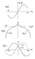
- FIG. 4 A typical course of the difference p14-p23 depending on the angle of incidence ß is shown in Fig. 4.
- the computer unit 15 can determine the respective angle of incidence ß by calculating the aforementioned quotient of differences.
- the value of the pressure difference p14 or p23 assigned to the previously determined value of the angle of incidence ß is divided by a coefficient c14 or c23, the size of which depends only on the respective value of the angle of incidence ß (and the shape of the respective body).
- a typical course of the coefficients c14 or c23 is shown depending on the angle of incidence ß.
- the computer unit 15 can arithmetically determine steering maneuvers with which the crosswind influence can be largely compensated for.
- actuators of an automatic steering of the vehicle e.g. an automatic rear wheel steering
- the cross wind influence can then be compensated for at least to such an extent that the driver's control of the vehicle is made considerably easier even in the case of very strong cross winds and high driving speeds.
- the openings 1 and 2 are opened in the vehicle longitudinal direction in the manner shown in FIG. 1, while the openings 3 and 4 directed towards the vehicle sides, but are arranged near the front of the vehicle or at the front corners of the vehicle.
- the openings 1 and 3 as well as 2 and 4 are arranged symmetrically to the vertical median longitudinal plane of the vehicle, because then the difference p14 - p23 with the inflow or flow around the plane (symmetrical about this plane) the value Has zero.
Landscapes
- Physics & Mathematics (AREA)
- General Physics & Mathematics (AREA)
- Measuring Fluid Pressure (AREA)
- Indicating Or Recording The Presence, Absence, Or Direction Of Movement (AREA)
- Aerodynamic Tests, Hydrodynamic Tests, Wind Tunnels, And Water Tanks (AREA)
Abstract
Description
Die Erfindung betrifft eine Vorrichtung zur Bestimmung von Seitenwindeinflüssen an Fahrzeugen, insbesondere Kraftfahrzeugen, mit einer Meß- und Rechnereinrichtung, welche bei Seitenwind auftretende Druckunterschiede zwischen Meßstellen auf gegenüberliegenden Fahrzeugseiten - insbesondere im Bereich der vorderen Fahrzeugecken - auswertet, indem z.B. für ein die Windrichtung relativ zum Fahrzeug wiedergebendes Signal der Quotient einer ersten Druckdifferenz zwischen einer ersten Meßstelle auf der einen Fahrzeugseite und einer zweiten dazu asymmetrischen Meßstelle auf der anderen Fahrzeugseite sowie einer zweiten Druckdifferenz zwischen einer dritten Meßstelle auf der einen Fahrzeugseite sowie einer vierten dazu asymmetrischen Meßstelle auf der anderen Fahrzeugseite gebildet und für ein den Staudruck des Seitenwindes wiedergebendes Signal die Druckdifferenz zwischen zwei auf unterschiedlichen Fahrzeugseiten asymmetrisch zueinander liegenden Meßstellen mit einem vorgegebenen bzw. vorgebbaren Faktor multiplikativ verknüpft wird, der von dem die Windrichtung wiedergebenden Signal abhängig ist, nach Patent P 38 16 057.9-09.The invention relates to a device for determining the effects of cross winds on vehicles, in particular motor vehicles, with a measuring and computer device which evaluates pressure differences occurring in cross winds between measuring points on opposite sides of the vehicle - in particular in the area of the front corners of the vehicle - by, for example, the direction of the wind relative to Vehicle reproducing signal of the quotient of a first pressure difference between a first measuring point on one side of the vehicle and a second asymmetrical measuring point on the other side of the vehicle and a second pressure difference between a third measuring point on one side of the vehicle and a fourth asymmetrical measuring point on the other side of the vehicle and For a signal representing the back pressure of the side wind, the pressure difference between two measuring points located asymmetrically to one another on different sides of the vehicle with a predetermined or specifiable factor is multiplicatively linked, which is dependent on the signal representing the wind direction, according to patent P 38 16 057.9-09.
Bei der in der angegebenen älteren Patentanmeldung beschriebenen Vorrichtung wird bei der Bestimmung der Windrichtung die Tatsache ausgenutzt, daß ein in üblicher Weise symmetrisch zur vertikalen Mittellängsebene geformtes Fahrzeug bei Seitenwind asymmetrisch zur vertikalen Mittellängsebene umströmt wird. Dabei können gemäß dieser älteren Patentanmeldung der Grad der Asymmetrie und damit der Einfallwinkel des Seitenwindes relativ zum Fahrzeug durch Auswertung des Druckes an wenigen Meßstellen an der Außenseite des Fahrzeuges bestimmt werden. Zur Bestimmung des Staudruckes genügt dann die Ermittlung einer Druckdifferenz an zwei beidseitig des Fahrzeuges positionierten Meßstellen, wobei diese Druckdifferenz noch mit einem mit dem Einfallwinkel korrelierten Korrekturfaktor multipliziert werden muß.In the device described in the cited older patent application, the fact that a vehicle shaped in a usual manner symmetrically to the vertical median longitudinal plane is flowed around asymmetrically to the vertical median longitudinal plane in crosswinds is used in determining the wind direction. According to this earlier patent application, the degree of asymmetry and thus the angle of incidence of the side wind relative to the vehicle can be determined by evaluating the pressure at a few measuring points on the outside of the vehicle. To determine the dynamic pressure, it is then sufficient to determine a pressure difference at two measuring points positioned on both sides of the vehicle, this pressure difference still having to be multiplied by a correction factor correlated with the angle of incidence.
Gemäß der älteren Patentanmeldung sind an der Außenseite an den jeweiligen Meßstellen bevorzugt Differenzdruckmesser angeordnet, die die Druckdifferenz zwischen ihrer nach außen weisenden Seite sowie ihrer Innenseite messen, welche mit einem allen Differenzdruckmessern gemeinsamen Referenzraum über Rohr- bzw. Schlauchleitungen verbunden ist. Der Referenzraum ist so ausgebildet bzw. angeordnet, daß gegebenenfalls in diesem Raum auftretende Druckschwankungen wesentlich langsamer verlaufen als auf der Außenseite der Differenzdruckmesser und damit außenseitig des Fahrzeuges auftretende Druckänderungen, insbesondere solche, die durch Seitenwind verursacht werden.According to the older patent application, differential pressure gauges are preferably arranged on the outside at the respective measuring points, which measure the pressure difference between their outward-facing side and their inside, which is connected to a reference space common to all differential pressure gauges via pipes or hoses. The reference room is designed or arranged in such a way that pressure fluctuations which may occur in this room run much more slowly than pressure changes occurring on the outside of the differential pressure meter and thus outside of the vehicle, in particular those which are caused by cross winds.
Hierbei wird der Tatsache Rechnung getragen, daß Differenzdruckmesser auch bei geringem konstruktivem Aufwand relativ genau arbeiten und für die Bestimmung des Einfallwinkels bzw. den Staudruck des Seitenwindes die Kenntnis der abso luten Druckwerte an den jeweiligen Meßstellen nicht erforderlich ist.This takes into account the fact that differential pressure gauges work relatively precisely even with little design effort and the knowledge of the abs. For determining the angle of incidence or the dynamic pressure of the side wind pressure values at the respective measuring points is not required.
Nach dem Patent P 38 16 057.9-09 sind die Meßstellen bzw. die Differenzdruckmesser vor allem im Bereich der vorderen Fahrzeugecken angeordnet, weil dort besonders große seitenwindabhängige Druckunterschiede auftreten.According to patent P 38 16 057.9-09, the measuring points or the differential pressure gauges are arranged primarily in the area of the front vehicle corners, because there are particularly large cross-wind-dependent pressure differences.
Im übrigen ist gemäß diesem Patent vorgesehen, die Differenzdruckmesser nahe der nach außen führenden Mündungen der mit dem gemeinsamen Referenzraum verbundenen Rohr- bzw. Schlauchleitungen anzubringen, um zu gewährleisten, daß die Differenzdruckmesser praktisch verzögerungsfrei auf Druckänderungen der Luft an der Fahrzeugaußenseite reagieren können.Moreover, according to this patent, it is provided that the differential pressure gauges are placed near the outlets of the pipes or hose lines connected to the common reference space, in order to ensure that the differential pressure gauges can react to pressure changes in the air on the outside of the vehicle practically without delay.
Aufgabe der Erfindung ist es nun, die eingangs angegebene Vorrichtung in konstruktiver Weise noch weiter zu vereinfachen.The object of the invention is now to further simplify the device specified at the outset in a constructive manner.
Diese Aufgabe wird erfindungsgemäß dadurch gelöst, daß zur Ermittlung der Druckunterschiede mindestens zwei Differenzdrucksensoren zwischen jeweils zwei gleichartigen Hohlleitungen (z.B. Rohre bzw. Schläuche) angeschlossen sind, die mit ihren vom jeweiligen Differenzdrucksensor entfernten offenen Enden an zueinander asymmetrischen Stellen beidseitig der Fahrzeuglängsachse nach außen münden, und daß die offenen Enden der Hohlleitungen an Öffnungen eines Stoßfängers angeordnet sind, welcher auch die Hohlleitungen sowie die zugeordneten Differenzdrucksensoren aufnimmt.This object is achieved in that, in order to determine the pressure differences, at least two differential pressure sensors are connected between each two identical hollow lines (for example pipes or hoses) which, with their open ends remote from the respective differential pressure sensor, open outward at mutually asymmetrical locations on both sides of the vehicle's longitudinal axis, and that the open ends of the hollow lines are arranged at openings of a bumper, which also receives the hollow lines and the associated differential pressure sensors.
Bei der Erfindung wird die überraschende Tatsache ausgenutzt, daß sich die Druckdifferenzen an den Mündungen der einem Differenzdrucksensor zugeordneten Hohlleitungen mittels des Differenzdrucksensors praktisch verzögerungsfrei bestimmen lassen, weil sich Druckänderungen an den Mündungen mit außerordentlich hoher Geschwindigkeit in den Hohlleitungen zum Differenzdrucksensor hin fortpflanzen. Bereits bei einem Innendurchmesser der Hohlleitungen von 1 mm kann - zumindest wenn, wie bei normalen Fahrzeugen, die Länge der Hohlleitungen in der Größenordnung von etwa 1 m liegt - mit einer Fortpflanzungsgeschwindigkeit der Druckänderungen in den Hohlleitungen im Bereich der Luft-Schallgeschwindigkeit gerechnet werden. Somit ermöglicht es die Erfindung, die Druckdifferenz an zwei voneinander entfernten Meßstellen mit jeweils nur einem Differenzdrucksensor zu ermitteln, so daß die Zahl der Drucksensoren auch bei einer relativ großen Anzahl von Meßstellen klein bleibt. Dementsprechend bleiben auch die Anforderungen an die Leistungsfähigkeit des Rechners bei der Auswertung der Sensorsignale relativ gering.In the invention, the surprising fact is exploited that the pressure differences at the mouths of the hollow lines assigned to a differential pressure sensor by means of the Differential pressure sensor can be determined practically without delay, because pressure changes at the mouths propagate at extremely high speed in the hollow pipes to the differential pressure sensor. Even with an inner diameter of the hollow pipes of 1 mm - at least if, like in normal vehicles, the length of the hollow pipes is of the order of about 1 m - a rate of propagation of the pressure changes in the hollow pipes in the range of the air-sound velocity can be expected. The invention thus makes it possible to determine the pressure difference at two measuring points that are distant from one another, each with only one differential pressure sensor, so that the number of pressure sensors remains small even with a relatively large number of measuring points. Accordingly, the requirements for the performance of the computer when evaluating the sensor signals remain relatively low.
Durch die Anordnung der Hohlleitungen sowie der zugeordneten Sensoren an den Stoßfängern des Fahrzeuges wird darüber hinaus die Möglichkeit geschaffen, ein Kraftfahrzeug mit einer Vorrichtung zur Bestimmung von Seitenwindeinflüssen nachzurüsten, ohne daß nennenswerte Karosseriearbeiten durchgeführt werden müssen. Im übrigen bieten die Stoßfänger aller Kraftfahrzeuge hinreichend Platz, die erfindungsgemäße Vorrichtung unterzubringen, und zwar mit geringstem konstruktivem Aufwand.The arrangement of the hollow lines and the associated sensors on the bumpers of the vehicle also creates the possibility of retrofitting a motor vehicle with a device for determining side wind influences without having to carry out any significant bodywork. In addition, the bumpers of all motor vehicles offer sufficient space to accommodate the device according to the invention, with the least design effort.
Des weiteren kann es zweckmäßig sein, die Differenzdrucksensoren gemeinsam mit einem Thermoelement in einem Kasten bzw. Gehäuse oder in einem Hohlraum am Stoßfänger unterzubringen, derart, daß alle Differenzdrucksensoren etwa gleicher Temperatur ausgesetzt sind. Auf diese Weise besteht die Mög lichkeit, die jeweilige Temperatur mit dem Thermoelement zu berücksichtigen und eine gegebenenfalls vorhandene Temperaturdrift der Differenzdrucksensoren auszugleichen.Furthermore, it can be expedient to accommodate the differential pressure sensors together with a thermocouple in a box or housing or in a cavity on the bumper, such that all differential pressure sensors are exposed to approximately the same temperature. In this way the possibility exists ability to take the respective temperature into account with the thermocouple and to compensate for any temperature drift of the differential pressure sensors.
Im übrigen wird hinsichtlich bevorzugter Merkmale der Erfindung auf die Ansprüche sowie die nachfolgende Erläuterung einer besonders bevorzugten Ausführungsform anhand der Zeichnung verwiesen.Otherwise, with regard to preferred features of the invention, reference is made to the claims and the following explanation of a particularly preferred embodiment with reference to the drawing.
Dabei zeigt
- Fig. 1 eine schematisierte Draufsicht auf einen Personenkraftwagen mit einer erfindungsgemäßen Vorrichtung zur Bestimmung von Seitenwindeinflüssen,
- Fig. 2 ein Diagramm, welches den Einfallwinkel ß des Seitenwindes relativ zum Fahrzeug in Abhängigkeit von einem Differenzenquotienten D₁₄₂₃ bzw. D₂₃₁₄ wiedergibt, welcher aus den Signalen der Differenzdrucksensoren ermittelbar ist,
- Fig. 3 ein Diagramm, welches zur Berechnung des Staudruckes dienende Koeffizienten c₂₃ bzw. c₁₄ in Abhängigkeit vom Einfallwinkel ß wiedergibt und
- Fig. 4 ein Diagramm, welches die Differenz der vorgenannten Koeffizienten zeigt.
- 1 is a schematic plan view of a passenger car with a device according to the invention for determining cross-wind influences,
- 2 is a diagram showing the angle of incidence β of the crosswind relative to the vehicle as a function of a difference quotient D₁₄₂₃ or D₂₃₁₄, which can be determined from the signals of the differential pressure sensors,
- Fig. 3 is a diagram which serves to calculate the dynamic pressure coefficients c₂₃ and c₁₄ depending on the angle of incidence ß and
- Fig. 4 is a diagram showing the difference of the aforementioned coefficients.
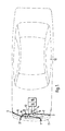
Gemäß Fig. 1 sind am vorderen Stoßfänger 11 eines Personenkraftwagens 12 symmetrisch zur vertikalen Mittellängsebene des Fahrzeuges vier Öffnungen 1 bis 4 angeordnet, an die sich Schlauch- bzw. Rohrleitungen 5 bis 8 anschließen. Die Schlauch- bzw. Rohrleitungen 5 bis 8 sind je paarweise mit Differenzdrucksensoren 9 und 10 verbunden, derart, daß der Differenzdrucksensor 9 den Differenzdruck zwischen den Schlauch- bzw. Rohrleitungen 5 und 8 und der Differenzdrucksensor 10 die Druckdifferenz zwischen den Schlauch- bzw. Rohrleitungen 6 und 7 registriert.1, four openings 1 to 4 are arranged on the
Die Schlauch- bzw. Rohrleitungen 5 bis 8 besitzen, ebenso wie die Öffnungen 1 bis 4,einen Innendurchmesser von ca. 1,5 mm, so daß sich Druckänderungen an den Öffnungen 1 bis 4 etwa mit Schallgeschwindigkeit zu den jeweils zugeordneten Differenzdrucksensoren 9 und 10 fortpflanzen.The hoses or pipelines 5 to 8, like the openings 1 to 4, have an inner diameter of approximately 1.5 mm, so that pressure changes at the openings 1 to 4 occur approximately at the speed of sound to the respectively assigned differential pressure sensors 9 and 10 reproduce.
Wenn davon ausgegangen wird, daß die Schlauch- bzw. Rohrleitungen 5 bis 8 jeweils ca. 70 cm lang sind, erfolgt die Fortpflanzung einer Druckänderung von einer der Öffnungen 1 bis 4 zu einem der Differenzdrucksensoren 9 und 10 jeweils innerhalb etwa 20 ms.If it is assumed that the hose or pipe lines 5 to 8 are each approximately 70 cm long, the propagation of a change in pressure from one of the openings 1 to 4 to one of the differential pressure sensors 9 and 10 takes place within approximately 20 ms.
Die Differenzdrucksensoren 9 und 10 sind vorzugsweise innerhalb eines Gehäuses bzw. Kastens 13 am Stoßfänger 11 untergebracht. Dabei sind das Gehäuse 13 bzw. der Kasten 13 so angeordnet bzw. ausgebildet, daß beide Differenzdrucksensoren 9 und 10 jeweils einer etwa gleichen Temperatur ausgesetzt sind, welche mittels eines im Gehäuse bzw. Kasten 13 angeordneten Thermoelementes 14 registriert werden kann.The differential pressure sensors 9 and 10 are preferably housed within a housing or
Die Signale der Differenzdrucksensoren 9 und 10 sowie des Thermoelementes 14 werden über entsprechende Signalleitungen einer Rechnereinheit 15 zugeführt, welche die genannten Signale zur Ermittlung der Seitenwindeinflüsse auswertet. Dabei dienen die Signale des Thermoelementes 14 dazu, eine eventuelle Temperaturdrift der Differenzdrucksensoren 9 und 10 rechnerisch zu kompensieren. Gegebenenfalls kann dazu auch eine gesonderte Schaltungseinheit 16 dienen, welche den Einfluß der Umgebungstemperatur auf die Diffe renzdrucksensoren 9 und 10 in Abhängigkeit von den Signalen des Thermoelementes 14 kompensiert, so daß die Rechnereinheit 15 lediglich solche Signale erhält, welche die Druckdifferenzen an den Differenzdrucksensoren 9 und 10 weitestgehend frei von Temperatureinflüssen wiedergeben.The signals of the differential pressure sensors 9 and 10 and of the thermocouple 14 are fed via corresponding signal lines to a
Mit der in Fig. 1 dargestellten Anordnung lassen sich die Einflüsse solcher Seitenwinde bestimmen, die eine der Fahrtrichtung des Fahrzeuges bei Vorwärtsfahrt entgegengerichtete Komponente aufweisen und zur Fahrzeuglängsachse einen Winkel zwischen +70° und -70° bilden.The arrangement shown in FIG. 1 can be used to determine the influences of such side winds which have a component which is opposite to the direction of travel of the vehicle when driving forward and which form an angle between + 70 ° and -70 ° to the longitudinal axis of the vehicle.
Dies wird nachfolgend erläutert.This is explained below.
Der Differenzdrucksensor 9 mißt die Druckdifferenz p₁₄ zwischen den Drucken an den Öffnungen 1 und 4; der Differenzdrucksensor 10 mißt die Druckdifferenz p₂₃ zwischen den Öffnungen 2 und 3. Zunächst wird die Differenz p₁₄-p₂₃ berechnet. Wenn die Fahrzeugkarosserie zur vertikalen Mittellängsebene derselben hinreichend symmetrisch ist, hat diese Differenz den Wert Null, wenn die Windrichtung mit der Fahrzeuglängsachse übereinstimmt. Falls der Wind bei dem Fahrzeug in Fig. 1 von schräg rechts vorne kommt, d.h. wenn der Einfallwinkel ß positive Werte aufweist, hat dann die genannte Differenz positive Werte; bei negativen Werten des Einfallwinkels ß, d.h. wenn der Wind von vorn schräg links auf das Fahrzeug einwirkt, wird die genannte Differenz negativ.The differential pressure sensor 9 measures the pressure difference p₁₄ between the pressures at openings 1 and 4; the differential pressure sensor 10 measures the pressure difference p₂₃ between the openings 2 and 3. First, the difference p₁₄-p₂₃ is calculated. If the vehicle body is sufficiently symmetrical with respect to the vertical central longitudinal plane thereof, this difference has the value zero if the wind direction coincides with the longitudinal axis of the vehicle. If the wind in the vehicle in Fig. 1 comes from obliquely right front, i.e. if the angle of incidence β has positive values, then the said difference has positive values; with negative values of the angle of incidence β, i.e. if the wind affects the vehicle diagonally from the left, the difference mentioned becomes negative.
Ein typischer Verlauf der Differenz p₁₄-p₂₃ in Abhängigkeit vom Einfallwinkel ß ist in Fig. 4 dargestellt.A typical course of the difference p₁₄-p₂₃ depending on the angle of incidence ß is shown in Fig. 4.
Wenn die Differenz p₁₄-p₂₃ positiv ist, d.h. bei Wind von rechts, wird der Differenzenquotient D₂₃₁₄ = p₂₃/p₁₄ ermittelt; falls die genannte Differenz negativ ist, d.h. bei von links auf das Fahrzeug einfallendem Wind, wird der Differenzenquotient D₁₄₂₃ = p₁₄/p₂₃ bestimmt.If the difference p₁₄-p₂₃ is positive, i.e. with wind from the right, the difference quotient D₂₃₁₄ = p₂₃ / p₁₄ is determined; if the said difference is negative, i.e. when the wind is incident on the vehicle from the left, the difference quotient D₁₄₂₃ = p₁₄ / p₂₃ is determined.
Die Werte der genannten Differenzenquotienten ändern sich mit der Größe des Einfallwinkels ß, wie es in Fig. 2 beispielhaft dargestellt ist. Dabei hängt der Verlauf der die Differenzenquotienten D₁₄₂₃ bzw. D₂₃₁₄ wiedergebenden Kurven von der Form des jeweiligen Fahrzeuges ab.The values of the difference quotients mentioned change with the size of the angle of incidence β, as is shown by way of example in FIG. 2. The course of the curves D₁₄₂₃ or D₂₃₁₄ representing the curves depends on the shape of the vehicle.
Indem also in einem Speicher der Rechnereinheit 15 den möglichen Werten der Differenzenquotienten D₁₄₂₃ bzw. D₂₃₁₄ die jeweiligen Einfallwinkel ß entsprechend der Form der jeweiligen Karosserie zugeordnet sind, kann die Rechnereinheit 15 den jeweiligen Einfallwinkel ß durch Berechnung der vorgenannten Differenzenquotienten ermitteln.So that in a memory of the
Nunmehr kann auch der jeweils vom Wind auf das Fahrzeug ausgeübte Staudruck ermittelt werden:Now the dynamic pressure exerted on the vehicle by the wind can also be determined:
Dazu wird der dem jeweils vorher ermittelten Wert des Einfallwinkels ß zugeordnete Wert der Druckdifferenz p₁₄ bzw. p₂₃ mit einem Beiwert c₁₄ bzw. c₂₃ dividiert dessen Größe lediglich von dem jeweiligen Wert des Einfallwinkels ß (sowie der Form der jeweiligen Karosserie) abhängt. In Fig. 3 ist ein typischer Verlauf der Beiwerte c₁₄ bzw. c₂₃ in Abhängigkeit vom Einfallwinkel ß dargestellt.For this purpose, the value of the pressure difference p₁₄ or p₂₃ assigned to the previously determined value of the angle of incidence ß is divided by a coefficient c₁₄ or c₂₃, the size of which depends only on the respective value of the angle of incidence ß (and the shape of the respective body). In Fig. 3 a typical course of the coefficients c₁₄ or c₂₃ is shown depending on the angle of incidence ß.
Aufgrund des jeweils ermittelten Staudruckes kann die Rechnereinheit 15 Lenkmanöver rechnerisch ermitteln, mit denen der Seitenwindeinfluß weitestgehend kompensiert werden kann. Durch entsprechende Ansteuerung von Stellorganen einer automatischen Lenkung des Fahrzeuges, z.B. einer automatischen Hinterradlenkung, kann dann der Seitenwindeinfluß zumindest so weit ausgeglichen werden, daß dem Fahrer die Beherrschung des Fahrzeuges auch bei sehr starken Seitenwinden und hohen Fahrgeschwindigkeiten wesentlich erleichtert wird.On the basis of the dynamic pressure determined in each case, the
Im Hinblick auf eine ausgeprägte Abhängigkeit der von den Differenzdrucksensoren 8 und 9 registrierten Druckdifferenzen vom Einfallwinkel ß des Seitenwindes ist es vorteilhaft, wenn die Öffnungen 1 und 2 in der in Fig. 1 dargestellten Weise in Fahrzeuglängsrichtung nach vorn geöffnet sind, während die Öffnungen 3 und 4 zu den Fahrzeugseiten hin gerichtet, jedoch nahe der Fahrzeugfrontseite bzw. an den vorderen Fahrzeugecken angeordnet sind.In view of a pronounced dependency of the pressure differences registered by the differential pressure sensors 8 and 9 on the angle of incidence β of the side wind, it is advantageous if the openings 1 and 2 are opened in the vehicle longitudinal direction in the manner shown in FIG. 1, while the openings 3 and 4 directed towards the vehicle sides, but are arranged near the front of the vehicle or at the front corners of the vehicle.
Zwar ist es vorteilhaft, wenn die Öffnungen 1 und 3 sowie 2 und 4 symmetrisch zur vertikalen Mittellängsebene des Fahrzeuges angeordnet sind, weil dann die Differenz p₁₄ - p₂₃ bei zu dieser Ebene symmetrischer Anströmung bzw. Umströmung des (zu dieser Ebene symmetrischen) Fahrzeuges den Wert Null hat. Jedoch ist es grundsätzlich auch möglich, die Öffnungen unsymmetrisch anzuordnen. In diesem Falle muß lediglich in Kauf genommen werden, daß die genannte Differenz bei einer bestimmten, schräg zur Fahrzeuglängsachse ausgerichteten Windrichtung den Wert Null hat, während beim Zusammenfallen von Fahrzeuglängsachse und Windrichtung für die genannte Differenz ein von Null abweichender Wert erhalten wird. Dadurch ändert sich prinzipiell nichts an der Arbeitsweise der Vorrichtung.It is advantageous if the openings 1 and 3 as well as 2 and 4 are arranged symmetrically to the vertical median longitudinal plane of the vehicle, because then the difference p₁₄ - p₂₃ with the inflow or flow around the plane (symmetrical about this plane) the value Has zero. In principle, however, it is also possible to arrange the openings asymmetrically. In this case it only has to be accepted that the said difference has the value zero for a certain wind direction oriented obliquely to the longitudinal axis of the vehicle, while a value deviating from zero is obtained for the mentioned difference when the longitudinal axis of the vehicle and the wind direction coincide. In principle, this does not change the functioning of the device.
Claims (4)
nach Patent P 38 16 057.9-09,
dadurch gekennzeichnet,
daß zur Ermittlung der Druckunterschiede (p₁₄,p₂₃) mindestens zwei Differenzdrucksensoren (9,10) zwischen jeweils zwei gleichartigen Hohlleitungen (5 bis 8) angeschlossen sind, die mit ihren vom jeweiligen Differenzdrucksensor (9,10) entfernten offenen Enden bzw. Öffnungen (1 bis 4) an zueinander asymmetrischen Stellen beiderseits der Fahrzeuglängsachse nach außen münden, und daß die offenen Enden der Hohlleitungen (5 bis 8) an Öffnungen (1 bis 4) eines Stoßfängers (11) angeordnet sind, welcher auch die Hohlleitungen (5 bis 8) sowie die zugeordneten Differenzdrucksensoren (9,10) aufnimmt.1.Device for determining the effects of cross winds on vehicles, in particular motor vehicles, with a measuring and computer device which evaluates pressure differences occurring in cross winds between measuring points on opposite sides of the vehicle - in particular in the area of the front corners of the vehicle - by, for example, reflecting the wind direction relative to the vehicle Signal of the quotient of a first pressure difference between a first measuring point on the one side of the vehicle and a second asymmetrical measuring point on the other side of the vehicle and a second pressure difference between a third measuring point on the one side of the vehicle and a fourth measuring point on the other side of the vehicle and for a dynamic pressure of the crosswind signal, the pressure difference between two measuring points located asymmetrically to one another on different sides of the vehicle is multiplied by a predetermined or predeterminable factor or coefficient is linked, which is dependent on the signal representing the wind direction,
according to patent P 38 16 057.9-09,
characterized,
that to determine the pressure differences (p₁₄, p₂₃) at least two differential pressure sensors (9,10) between each two similar hollow lines (5 to 8) are connected, with their open ends or openings (1 to 4) remote from the respective differential pressure sensor (9, 10) at mutually asymmetrical locations on both sides of the vehicle's longitudinal axis, and that the open ends of the Hollow lines (5 to 8) are arranged at openings (1 to 4) of a bumper (11) which also receives the hollow lines (5 to 8) and the assigned differential pressure sensors (9, 10).
dadurch gekennzeichnet,
daß die Differenzdrucksensoren (9,10) gemeinsam mit einem Thermoelement (14) in einem Kasten bzw. Gehäuse (13) oder einem Hohlraum am Stoßfänger (11) untergebracht sind, derart, daß alle Differenzdrucksensoren etwa gleicher Temperatur ausgesetzt sind und eine etwa gleiche Temperaturdrift aufweisen.2. Device according to claim 1,
characterized,
that the differential pressure sensors (9, 10) are housed together with a thermocouple (14) in a box or housing (13) or a cavity on the bumper (11), such that all differential pressure sensors are exposed to approximately the same temperature and approximately the same temperature drift exhibit.
dadurch gekennzeichnet,
daß der Innendurchmesser der Hohlleitungen (5 bis 8) bzw. der Öffnungen (1 bis 4) größer als 1 mm ist und z.B. bei 1,5 mm liegt.3. Device according to one of claims 1 or 2,
characterized,
that the inner diameter of the hollow pipes (5 to 8) or the openings (1 to 4) is greater than 1 mm and is, for example, 1.5 mm.
dadurch gekennzeichnet,
daß die Hohlleitungen (5 bis 8) durch Hohlräume im Stoßfänger (11) gebildet werden, welche jeweils durch eine Öffnung (1 bis 4) nach außen münden.4. Device according to one of claims 1 to 3,
characterized,
that the hollow lines (5 to 8) are formed by cavities in the bumper (11), each of which opens out through an opening (1 to 4).
Applications Claiming Priority (2)
| Application Number | Priority Date | Filing Date | Title |
|---|---|---|---|
| DE19893923854 DE3923854A1 (en) | 1988-05-11 | 1989-07-19 | Side-wind measuring system for motor vehicle |
| DE3923854 | 1989-07-19 |
Publications (3)
| Publication Number | Publication Date |
|---|---|
| EP0408886A2 true EP0408886A2 (en) | 1991-01-23 |
| EP0408886A3 EP0408886A3 (en) | 1991-10-09 |
| EP0408886B1 EP0408886B1 (en) | 1994-01-26 |
Family
ID=6385361
Family Applications (1)
| Application Number | Title | Priority Date | Filing Date |
|---|---|---|---|
| EP90110967A Expired - Lifetime EP0408886B1 (en) | 1989-07-19 | 1990-06-09 | Fender with a measuring and computing arrangement serving for the determination of cross-wind influences on vehicles |
Country Status (4)
| Country | Link |
|---|---|
| US (1) | US5119673A (en) |
| EP (1) | EP0408886B1 (en) |
| JP (1) | JPH03105256A (en) |
| ES (1) | ES2050881T3 (en) |
Cited By (4)
| Publication number | Priority date | Publication date | Assignee | Title |
|---|---|---|---|---|
| EP0529244A1 (en) * | 1991-08-22 | 1993-03-03 | Dr.Ing.h.c. F. Porsche Aktiengesellschaft | Sensor for measuring influence of side wind for a vehicle |
| WO2007022177A2 (en) * | 2005-08-16 | 2007-02-22 | Honeywell International Inc. | Methods and system for determining angles of attack and sideslip using flow sensors |
| CN104458295A (en) * | 2014-12-29 | 2015-03-25 | 成都市第一建筑工程公司 | Construction method for crosswind multiphase flow system for high speed train test |
| CN115773856A (en) * | 2023-02-09 | 2023-03-10 | 江苏永成汽车零部件股份有限公司 | Automobile bumper impact test device |
Families Citing this family (8)
| Publication number | Priority date | Publication date | Assignee | Title |
|---|---|---|---|---|
| US5309373A (en) * | 1990-07-23 | 1994-05-03 | Illinois Tool Works Inc. | Apparatus and method for wind-corrected measurement of steering pull on a vehicle |
| DE4127725A1 (en) * | 1991-08-22 | 1993-02-25 | Porsche Ag | METHOD AND DEVICE FOR MINIMIZING THE SIDEWIND INFLUENCE ON THE DRIVING BEHAVIOR OF A VEHICLE |
| US5546799A (en) * | 1994-12-09 | 1996-08-20 | Digital Control Corp. | Draft monitoring device mounted on motor vehicle to determine wind speed relative to ground |
| US6185489B1 (en) | 1998-06-12 | 2001-02-06 | Roger Dean Strickler | Vehicle overturn monitor |
| FR2848522B1 (en) | 2002-12-13 | 2006-01-21 | Renault Sas | MOTOR VEHICLE EQUIPPED WITH A DEVICE FOR AERODYNAMIC TRAIN REDUCTION PLATE |
| FR2883544B1 (en) * | 2005-03-22 | 2008-10-10 | Peugeot Citroen Automobiles Sa | DEVICE FOR COMPENSATING DISTURBANCES CAUSED BY A SIDE WIND ON A MOTOR VEHICLE |
| US7513146B2 (en) * | 2006-05-01 | 2009-04-07 | Daimler Trucks North America Llc | Vehicle wind tunnel balance |
| FR2909181B1 (en) * | 2006-11-29 | 2009-07-10 | Peugeot Citroen Automobiles Sa | MOTOR VEHICLE HAVING A DEVICE FOR DETERMINING EFFECTS OF THE SIDE WIND. |
Citations (4)
| Publication number | Priority date | Publication date | Assignee | Title |
|---|---|---|---|---|
| DE2819122A1 (en) * | 1978-04-29 | 1979-11-08 | Wulf Thoma | Side-wind warning device for vehicles - has transverse total pressure tubes and longitudinal static pressure measurement wind channel |
| DE3512378A1 (en) * | 1984-04-04 | 1985-10-17 | Nissan Motor Co., Ltd., Yokohama, Kanagawa | MOTOR VEHICLE WITH ADJUSTABLE AERODYNAMIC ACCESSORIES AND CONTROL DEVICE THEREFOR |
| DE3816057C1 (en) * | 1988-05-11 | 1989-04-13 | Daimler-Benz Aktiengesellschaft, 7000 Stuttgart, De | |
| EP0315497A1 (en) * | 1987-11-04 | 1989-05-10 | Automobiles Peugeot | Device for measuring the resulting aerodynamical force acting on a vehicle |
Family Cites Families (1)
| Publication number | Priority date | Publication date | Assignee | Title |
|---|---|---|---|---|
| US3149491A (en) * | 1961-07-05 | 1964-09-22 | Sissenwine Norman | Airborne jet stream detector |
-
1990
- 1990-06-09 ES ES90110967T patent/ES2050881T3/en not_active Expired - Lifetime
- 1990-06-09 EP EP90110967A patent/EP0408886B1/en not_active Expired - Lifetime
- 1990-07-13 JP JP2184393A patent/JPH03105256A/en active Granted
- 1990-07-18 US US07/553,651 patent/US5119673A/en not_active Expired - Fee Related
Patent Citations (4)
| Publication number | Priority date | Publication date | Assignee | Title |
|---|---|---|---|---|
| DE2819122A1 (en) * | 1978-04-29 | 1979-11-08 | Wulf Thoma | Side-wind warning device for vehicles - has transverse total pressure tubes and longitudinal static pressure measurement wind channel |
| DE3512378A1 (en) * | 1984-04-04 | 1985-10-17 | Nissan Motor Co., Ltd., Yokohama, Kanagawa | MOTOR VEHICLE WITH ADJUSTABLE AERODYNAMIC ACCESSORIES AND CONTROL DEVICE THEREFOR |
| EP0315497A1 (en) * | 1987-11-04 | 1989-05-10 | Automobiles Peugeot | Device for measuring the resulting aerodynamical force acting on a vehicle |
| DE3816057C1 (en) * | 1988-05-11 | 1989-04-13 | Daimler-Benz Aktiengesellschaft, 7000 Stuttgart, De |
Cited By (8)
| Publication number | Priority date | Publication date | Assignee | Title |
|---|---|---|---|---|
| EP0529244A1 (en) * | 1991-08-22 | 1993-03-03 | Dr.Ing.h.c. F. Porsche Aktiengesellschaft | Sensor for measuring influence of side wind for a vehicle |
| US5315868A (en) * | 1991-08-22 | 1994-05-31 | Ing. H.C.F. Porsche Ag | Sensor for detecting the influence of cross wind on a vehicle |
| WO2007022177A2 (en) * | 2005-08-16 | 2007-02-22 | Honeywell International Inc. | Methods and system for determining angles of attack and sideslip using flow sensors |
| WO2007022177A3 (en) * | 2005-08-16 | 2010-06-17 | Honeywell International Inc. | Methods and system for determining angles of attack and sideslip using flow sensors |
| CN104458295A (en) * | 2014-12-29 | 2015-03-25 | 成都市第一建筑工程公司 | Construction method for crosswind multiphase flow system for high speed train test |
| CN104458295B (en) * | 2014-12-29 | 2017-01-18 | 成都市第一建筑工程公司 | Construction method for crosswind multiphase flow system for high speed train test |
| CN115773856A (en) * | 2023-02-09 | 2023-03-10 | 江苏永成汽车零部件股份有限公司 | Automobile bumper impact test device |
| CN115773856B (en) * | 2023-02-09 | 2023-04-25 | 江苏永成汽车零部件股份有限公司 | Automobile bumper impact test device |
Also Published As
| Publication number | Publication date |
|---|---|
| JPH0549942B2 (en) | 1993-07-27 |
| EP0408886B1 (en) | 1994-01-26 |
| US5119673A (en) | 1992-06-09 |
| JPH03105256A (en) | 1991-05-02 |
| EP0408886A3 (en) | 1991-10-09 |
| ES2050881T3 (en) | 1994-06-01 |
Similar Documents
| Publication | Publication Date | Title |
|---|---|---|
| EP1747973B1 (en) | Method for assisting in vehicle parking | |
| DE3816057C1 (en) | ||
| EP0408886B1 (en) | Fender with a measuring and computing arrangement serving for the determination of cross-wind influences on vehicles | |
| DE102004050149A1 (en) | Drawbar and trailer angle determining method, involves ascertaining drawbar and trailer`s characteristic edges and lines from video stream of sensor e.g. video camera, and determining angles from geometrical conditions of characteristic | |
| EP1571638B1 (en) | Method for distance warning for a vehicle and distance warning unit | |
| EP0529244B1 (en) | Sensor for measuring influence of side wind for a vehicle | |
| DE602004001725T2 (en) | Aerodynamic device for a vehicle; Vehicle with such an aerodynamic device | |
| EP1755921A1 (en) | Method and device for assisting the performance of a parking maneuver of a vehicle | |
| EP1827930A1 (en) | Determination of the angle of inclination for a motorbike | |
| DE112009003590T5 (en) | ultrasound transducer | |
| DE102011111051A1 (en) | Method for assisting driver during controlling vehicle, involves evaluating and recording image corresponding to performance and by stereo camera to determine position and orientation of vehicle relative to position mark | |
| DE102004045717B4 (en) | Device for automatically adjusting the light axis direction of vehicle headlights | |
| DE112018005415T5 (en) | Control device and control method for controlling the behavior of a motorcycle | |
| DE19941034A1 (en) | Adjustment device with an adjustment device for a headlight or for a distance sensor of a vehicle | |
| DE19958492A1 (en) | Method to determine unstable vehicle state; involves determine difference between measured transverse acceleration and transverse acceleration calculated from steering wheel angle and vehicle speed | |
| DE102010008079A1 (en) | Method for detecting cross-wind of motor vehicle, involves synchronizing transmission signals of ultrasonic sensor units, and determining cross-wind from displacement of frequency between transmission signals and reception signal of units | |
| DE19638189A1 (en) | Sound distribution system for road vehicle | |
| DE4127750C1 (en) | Automotive equipment improving stability of car and trailer linkage - uses sensors or measurement value pick=ups to register undesired swing of trailer and automatic auxiliary linkage to counteract it | |
| DE19620393A1 (en) | Car with parking and manoeuvring aid | |
| DE102008022971A1 (en) | Adjustment examining method for ultrasonic sensor utilized for measuring distance during parking assistance of driver of car, involves comparing measured distance of sensor from edge of parking space with computed distance | |
| DE3923854A1 (en) | Side-wind measuring system for motor vehicle | |
| DE102004055372A1 (en) | Parking assistance for a vehicle and parking assistance procedure | |
| DE19603122C2 (en) | rear spoiler | |
| EP0947412B1 (en) | Control device for influencing the drive dynamics of a four-wheeled vehicle | |
| DE3146612C2 (en) | Steering system for automobiles |
Legal Events
| Date | Code | Title | Description |
|---|---|---|---|
| PUAI | Public reference made under article 153(3) epc to a published international application that has entered the european phase |
Free format text: ORIGINAL CODE: 0009012 |
|
| AK | Designated contracting states |
Kind code of ref document: A2 Designated state(s): ES FR GB |
|
| PUAL | Search report despatched |
Free format text: ORIGINAL CODE: 0009013 |
|
| AK | Designated contracting states |
Kind code of ref document: A3 Designated state(s): ES FR GB |
|
| 17P | Request for examination filed |
Effective date: 19910828 |
|
| 17Q | First examination report despatched |
Effective date: 19921202 |
|
| GRAA | (expected) grant |
Free format text: ORIGINAL CODE: 0009210 |
|
| AK | Designated contracting states |
Kind code of ref document: B1 Designated state(s): ES FR GB |
|
| GBT | Gb: translation of ep patent filed (gb section 77(6)(a)/1977) |
Effective date: 19940221 |
|
| ET | Fr: translation filed | ||
| REG | Reference to a national code |
Ref country code: ES Ref legal event code: FG2A Ref document number: 2050881 Country of ref document: ES Kind code of ref document: T3 |
|
| PLBE | No opposition filed within time limit |
Free format text: ORIGINAL CODE: 0009261 |
|
| STAA | Information on the status of an ep patent application or granted ep patent |
Free format text: STATUS: NO OPPOSITION FILED WITHIN TIME LIMIT |
|
| 26N | No opposition filed | ||
| PGFP | Annual fee paid to national office [announced via postgrant information from national office to epo] |
Ref country code: FR Payment date: 19950530 Year of fee payment: 6 |
|
| PGFP | Annual fee paid to national office [announced via postgrant information from national office to epo] |
Ref country code: GB Payment date: 19950531 Year of fee payment: 6 |
|
| PGFP | Annual fee paid to national office [announced via postgrant information from national office to epo] |
Ref country code: ES Payment date: 19950620 Year of fee payment: 6 |
|
| PG25 | Lapsed in a contracting state [announced via postgrant information from national office to epo] |
Ref country code: GB Effective date: 19960609 |
|
| PG25 | Lapsed in a contracting state [announced via postgrant information from national office to epo] |
Ref country code: ES Free format text: LAPSE BECAUSE OF NON-PAYMENT OF DUE FEES Effective date: 19960610 |
|
| GBPC | Gb: european patent ceased through non-payment of renewal fee |
Effective date: 19960609 |
|
| PG25 | Lapsed in a contracting state [announced via postgrant information from national office to epo] |
Ref country code: FR Effective date: 19970228 |
|
| REG | Reference to a national code |
Ref country code: FR Ref legal event code: ST |
|
| REG | Reference to a national code |
Ref country code: ES Ref legal event code: FD2A Effective date: 19990503 |