EP0408622B1 - Schnellverriegelungsmechanismus für bürotrennwandpaneele - Google Patents
Schnellverriegelungsmechanismus für bürotrennwandpaneele Download PDFInfo
- Publication number
- EP0408622B1 EP0408622B1 EP89903897A EP89903897A EP0408622B1 EP 0408622 B1 EP0408622 B1 EP 0408622B1 EP 89903897 A EP89903897 A EP 89903897A EP 89903897 A EP89903897 A EP 89903897A EP 0408622 B1 EP0408622 B1 EP 0408622B1
- Authority
- EP
- European Patent Office
- Prior art keywords
- locking bar
- panel
- spring
- panels
- post
- Prior art date
- Legal status (The legal status is an assumption and is not a legal conclusion. Google has not performed a legal analysis and makes no representation as to the accuracy of the status listed.)
- Expired - Lifetime
Links
Images

Classifications
-
- E—FIXED CONSTRUCTIONS
- E05—LOCKS; KEYS; WINDOW OR DOOR FITTINGS; SAFES
- E05B—LOCKS; ACCESSORIES THEREFOR; HANDCUFFS
- E05B65/00—Locks or fastenings for special use
- E05B65/08—Locks or fastenings for special use for sliding wings
- E05B65/087—Locks or fastenings for special use for sliding wings the bolts sliding parallel to the wings
-
- E—FIXED CONSTRUCTIONS
- E04—BUILDING
- E04B—GENERAL BUILDING CONSTRUCTIONS; WALLS, e.g. PARTITIONS; ROOFS; FLOORS; CEILINGS; INSULATION OR OTHER PROTECTION OF BUILDINGS
- E04B1/00—Constructions in general; Structures which are not restricted either to walls, e.g. partitions, or floors or ceilings or roofs
- E04B1/38—Connections for building structures in general
- E04B1/61—Connections for building structures in general of slab-shaped building elements with each other
- E04B1/6108—Connections for building structures in general of slab-shaped building elements with each other the frontal surfaces of the slabs connected together
- E04B1/612—Connections for building structures in general of slab-shaped building elements with each other the frontal surfaces of the slabs connected together by means between frontal surfaces
- E04B1/6125—Connections for building structures in general of slab-shaped building elements with each other the frontal surfaces of the slabs connected together by means between frontal surfaces with protrusions on the one frontal surface co-operating with recesses in the other frontal surface
- E04B1/6141—Connections for building structures in general of slab-shaped building elements with each other the frontal surfaces of the slabs connected together by means between frontal surfaces with protrusions on the one frontal surface co-operating with recesses in the other frontal surface the connection made by an additional locking key
-
- E—FIXED CONSTRUCTIONS
- E04—BUILDING
- E04B—GENERAL BUILDING CONSTRUCTIONS; WALLS, e.g. PARTITIONS; ROOFS; FLOORS; CEILINGS; INSULATION OR OTHER PROTECTION OF BUILDINGS
- E04B1/00—Constructions in general; Structures which are not restricted either to walls, e.g. partitions, or floors or ceilings or roofs
- E04B1/38—Connections for building structures in general
- E04B1/61—Connections for building structures in general of slab-shaped building elements with each other
- E04B1/6108—Connections for building structures in general of slab-shaped building elements with each other the frontal surfaces of the slabs connected together
- E04B1/612—Connections for building structures in general of slab-shaped building elements with each other the frontal surfaces of the slabs connected together by means between frontal surfaces
- E04B1/6179—Connections for building structures in general of slab-shaped building elements with each other the frontal surfaces of the slabs connected together by means between frontal surfaces with protrusions and recesses on each frontal surface
-
- F—MECHANICAL ENGINEERING; LIGHTING; HEATING; WEAPONS; BLASTING
- F16—ENGINEERING ELEMENTS AND UNITS; GENERAL MEASURES FOR PRODUCING AND MAINTAINING EFFECTIVE FUNCTIONING OF MACHINES OR INSTALLATIONS; THERMAL INSULATION IN GENERAL
- F16B—DEVICES FOR FASTENING OR SECURING CONSTRUCTIONAL ELEMENTS OR MACHINE PARTS TOGETHER, e.g. NAILS, BOLTS, CIRCLIPS, CLAMPS, CLIPS OR WEDGES; JOINTS OR JOINTING
- F16B2200/00—Constructional details of connections not covered for in other groups of this subclass
- F16B2200/20—Connections with hook-like parts gripping behind a blind side of an element to be connected
- F16B2200/205—Connections with hook-like parts gripping behind a blind side of an element to be connected the hook being a separate retainer
-
- F—MECHANICAL ENGINEERING; LIGHTING; HEATING; WEAPONS; BLASTING
- F16—ENGINEERING ELEMENTS AND UNITS; GENERAL MEASURES FOR PRODUCING AND MAINTAINING EFFECTIVE FUNCTIONING OF MACHINES OR INSTALLATIONS; THERMAL INSULATION IN GENERAL
- F16B—DEVICES FOR FASTENING OR SECURING CONSTRUCTIONAL ELEMENTS OR MACHINE PARTS TOGETHER, e.g. NAILS, BOLTS, CIRCLIPS, CLAMPS, CLIPS OR WEDGES; JOINTS OR JOINTING
- F16B2200/00—Constructional details of connections not covered for in other groups of this subclass
- F16B2200/40—Clamping arrangements where clamping parts are received in recesses of elements to be connected
-
- Y—GENERAL TAGGING OF NEW TECHNOLOGICAL DEVELOPMENTS; GENERAL TAGGING OF CROSS-SECTIONAL TECHNOLOGIES SPANNING OVER SEVERAL SECTIONS OF THE IPC; TECHNICAL SUBJECTS COVERED BY FORMER USPC CROSS-REFERENCE ART COLLECTIONS [XRACs] AND DIGESTS
- Y10—TECHNICAL SUBJECTS COVERED BY FORMER USPC
- Y10T—TECHNICAL SUBJECTS COVERED BY FORMER US CLASSIFICATION
- Y10T403/00—Joints and connections
- Y10T403/60—Biased catch or latch
- Y10T403/602—Biased catch or latch by separate spring
Definitions
- the invention herein resides in the art of office panel systems and, more particularly, to a locking mechanism for such systems.
- This invention presents a new type of locking mechanism for the temporary office partitions known as "office panel systems".
- sections of these office panels are configured in open office areas to create cubicles or private work spaces by dividing the greater work area into smaller sections.
- these panels provide temporary, non-fixed walls for improved visual and acoustic privacy, as well as for the mounting of cabinets and work surfaces.
- US-A-3 731 956 relates to a system for joining adjacent building panels, each panel having pegs which are received in recesses in the adjacent panel.
- a central flat connector having key slots therein through which the pegs pass is pushed up or down to lock the panels together.
- FR-A-2 543 627 relates to a similar system using a tab having a wedge shaped surface which is received in a slot or an adjustable locking member.
- the present invention provides in a partition wall panel, the improvement, comprising a vertical post at one end of the panel; a tab extending from said post; a slot within said post, said slot adapted to receive a tab from an adjoining panel; a locking bar in juxtaposition to said slot and adapted for making securing engagement with said tab from the adjoining panel, said locking bar being slidably received within a channel within said post, characterized by a spring received by said vertical post and engaging said locking bar, said spring biasing said locking bar into securing engagement, and a pull ring positioned at a bottom end of said vertical post and secured to one end of said locking bar for allowing manual actuation of said locking bar against biasing of said spring.
- the panels may be locked securely together, merely by aligning the locking surfaces of two panels and firmly pushing the panels together. No tools are required for connection or separation of adjoining panels.
- the locking mechanism is an integral part of each of the two vertical posts in the panel's rectangular framework.
- the metal tabs of either panel enter corresponding slots on the adjoining panel.
- the slots are cut through two metal surfaces, the first of which is a flat metal "locking" bar which is capable of sliding up and down, and is spring-loaded at one end.
- the second metal surface is the actual vertical post itself.
- each tab As the tabs penetrate into the slots, the angled lower edge of each tab meets the bottom edge of each slot and deflects the locking bar downward against tension supplied by the spring mounted at the bottom of the locking bar.
- the locking bar encounters a notch in the bottom edge of the tab, and due to existing upward spring tension on the locking bar, the bar travels upward into the notch, thereby preventing the tab from withdrawing from the slot.
- each locking bar is pulled down against spring tension, thereby freeing the bar from the notches in the opposite panel's tabs and allowing the panels to be pulled apart.
- an extruded aluminum post 10 is used for both vertical sides of the panel's rectangular framework.
- An extruded aluminum I beam 12 is used for the lower horizontal component of the panel's rectangular framework, interconnecting the vertical side posts 10.
- An aluminum locking bar 14 is slidably received within an open faced channel 16 on the outside of the panel posts 10.
- the locking bar 14 is of a length dependent on the height of the vertical posts 10, and is preferably of stock 0.0158 cm. (1/16 inch) thick and 0.476 cm. (3/16 inch) wide.
- a 2.54 cm. (1 inch) diameter split metal pull-ring 20 attaches to the bottom end of the locking bar 14 to allow release of the locking action as will be discussed later herein.
- the extruded aluminum posts 10 are cut to various lengths depending on the intended height of the overall panel. After cutting, the posts 10 have slots 22, which are preferably 0.396 cm. (5/32 inch) wide x 2.54 cm. (1 inch) high, stamped in the locking bar's channel 16 starting 43.18 cm. (17 inches) from the bottom of the post and continuing at evenly spaced intervals toward the top.
- a cutout 24 measuring 1.587 cm. (5/8 inch) wide and 8.89 cm. (3.5 inches) high is milled to provide room for the spring 18.
- Tabs 26 are stamped in the flange 28 that extends perpendicularly away from the outside surface of the post 10, every 45.72 cm. (18 inches) starting at the bottom of the post and continuing toward the top. As shown in the drawings, the tabs 26 and slots 22 are preferably in horizontal alignment.
- the bottom of the locking bar 14 is stamped to remove 0.635 cm. (1/4 inch) from one side for a length of 8.255 cm. (3 1/4 inches) starting at the bottom as designated at 30. This is done to allow the spring 18 to fit over the bottom of the bar 14 and allow the bar to rest on the top of the spring. Then a 0.317 cm. (1/8 inch) hole 32 is stamped 0.476 cm. (3/16 inch) from the bottom and centered in the remaining portion of the locking bar, to accept installation of the metal pull-ring 20.
- a slot 34 1.508 cm. (19/32 inch) wide x 0.238 cm. (3/32 inch) deep, is stamped into the top of the I beam 12 directly under the locking bar channel 16 in the post, to allow the passage of the locking bar 14.
- Four 0.317 cm. (1/8 inch) holes are stamped into the top of the I beam 12, to allow mounting screws to pass up through the top of the I beam into threaded channels 36 in the corners at the bottom of each post.
- the spring 18 is placed in the cutout area 24 in the bottom of the post 10, atop the I beam.
- the locking bar 14 is then slid into the locking bar channel 16, keeping the slots to the right as viewed when facing the panel end.
- the locking bar 14 is then passed through the spring 18 and through the slot in the top of the I beam 12.
- the spring 18 is then compressed enough to allow the hole 32 in the bottom of the locking bar 14 to be accessible from underneath the top of the I beam 12.
- the metal pull-ring 20 is then inserted into the hole in the bottom of the locking bar and tension on the spring is released.
- the panel ends are aligned facing each other. They are then moved together until the tabs 26 from each begin to enter the slots 22 from the other. The panels are pressed together until they meet and a clicking sound is heard, evidencing engagement of the slots 38 of the locking bar 14 with the notches 40 of the tabs 26. As will be apparent to those skilled in the art, engagement of the beveled tabs 26 in the slots 38 deflects the locking bar 14 against the biasing of the spring 18 until the bar 14 snaps into locking engagement with the notch 40 securing the locking bar 14. The panels are now locked together.
- Fig. 1 it can be seen that the tab 26 is of a shape that has been stamped out of the original extruded post form. Parallel to the tab 26 is shown the slot 38 in the sliding locking bar 14. Directly behind the locking bar slot 38, and, therefore, not visible in this drawing, is a matching slot in the vertical post 10 itself.
- the locking bar 14 is contained by the open faced channel 16 in the vertical post 10, which allows the locking bar 14 to slide up or down.
- a cutout 24 in the bottom of the post 10 accepts a spring 18.
- the end of the locking bar 14 passes through the spring 18 until the upper part of the stamped out section 30 rests on the top of the spring 18. This is possible due to a reduction in the diameter of the locking bar caused by the stamped cutout.
- the locking bar passes through a stamped out slot in the top of the I beam.
- the spring pushes the sliding bar up until the split metal pull ring meets the underside of the I beam's top surface.
- the locking bar normally remains in this position with some spring tension active.
- a cross sectional view of the extruded aluminum horizontal I beam 12 may be seen.
- the vertical post 10 mounts on top of this I beam 12 by means of four self tapping metal SCrewS that tap into four circular channels 36 in the bottom of the post 10 as best shown in Fig. 3.
- a cross sectional view of the extruded aluminum vertical post 10 can be seen.
- the four circular channels 36 used to receive the self tapping metal screws which attach the post 10 to the I beam 12 may be seen at corners of the extrusion.
- the arm or flange 28 from which the tab 26 is stamped is also shown, as is the open faced channel 16 which accepts the sliding locking bar 14.
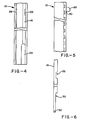
- Fig. 4 there is presented a front view of the extruded aluminum vertical post 10.
- the lower section of the post 10 shows the rounded cutout shape 24 which is milled away to accept the compression spring 18. Through this spring will pass the end section of the sliding locking bar 24.
- the upper section shows the stamped out slot 22 that accepts the tab 26 from the adjoining panel.
- Fig. 5 presents a side view of the tab 26, showing a notch 40 on its underside, into which the sliding locking bar 14 will fit and become secured as two adjoining panels are pressed together.
- the small rectangular stamped out sections of the flange 18 are part of the same stamping tool's work, but are unrelated to the quick-locking mechanism of the instant invention.
- a small hole 32 is stamped in the very bottom to accept the split metal pull ring 20.
- a portion of the end segment of the bar is stamped away at 30, making the bar narrower. This allows the locking bar 14 to pass through the spring 18 until the wider part of the locking bar meets the top of the spring.
- the rectangular section 38 stamped out of the locking bar higher up, is the slot that accepts the corresponding tab 26 from an adjoining panel.
Landscapes
- Engineering & Computer Science (AREA)
- Architecture (AREA)
- Physics & Mathematics (AREA)
- Electromagnetism (AREA)
- Civil Engineering (AREA)
- Structural Engineering (AREA)
- Joining Of Building Structures In Genera (AREA)
- Furniture Connections (AREA)
- Cookers (AREA)
- Fencing (AREA)
Claims (5)
- Trennwandpaneel mit Verbesserung, anfassend eine vertikale Stütze (10) an einem Ende des Paneels; einen Zapfen (26), der von der geannten Stütze hervorsteht; einen Schlitz (38) im Inneren der genannten Stüzte, wobei der Schlitz einen Zapfen von einem angrenzenden Paneel aufnimmt; einen Sperriegel (14) neben dem Schlitz zum befestigenden Eingriff mit dem Zapfen von dem angrenzenden Paneel, wobei der Sperriegel (14) von einer Auskehlung (16) im Inneren der Stütze (10) gleitend aufgenommen wird,
dadurch gekennzeichnet, daß eine Feder (18) von der vertikalen Stütze (10) gehalten wird und in den Sperriegel (14) eingreift, die Feder den Sperriegel zu einem befestigenden Eingriff vorspannt und ein Zugring (20) an der Unterseite der vertikalen Stütze (10) angeordnet und an einem Ende des Sperriegels (14) befestigt ist, um eine manuelles Betätigen des Sperriegels gegen die vorspannung der Feder (18) zu ermöglichen. - Verbesserung nach Anspruch 1, dadurch gekennzeichnet, daß die Zapfen (26) angefast sind, um einen durchfedernden Eingriff mit dem Sperriegel (14) herzustellen.
- Verbesserung nach Anspruch 2, dadurch gekennzeichnet, daß jeder Zapfen (26) an einem Ende davon eine Kerbe (40) zum Spanneingriff mit dem Sperriegel (14) aufweist.
- Verbesserung nach Anspruch 1, gekennzeichnet durch ein Fußteil (12), das an der vertikalen Stütze (10) an einem Unterkantenabschnitt des Paneels befestigt ist.
- Verbesserung nach Anspruch 1, dadurch gekennzeichnet, daß der Zapfen (26) und der Schlitz (38) der vertikalen Stütze (10) zueinander horizontal ausgerichtet sind.
Applications Claiming Priority (2)
| Application Number | Priority Date | Filing Date | Title |
|---|---|---|---|
| US164187 | 1988-03-04 | ||
| US07/164,187 US5004371A (en) | 1988-03-04 | 1988-03-04 | Office partition, panel-to-panel quick-locking mechanism |
Publications (2)
| Publication Number | Publication Date |
|---|---|
| EP0408622A1 EP0408622A1 (de) | 1991-01-23 |
| EP0408622B1 true EP0408622B1 (de) | 1993-02-17 |
Family
ID=22593366
Family Applications (1)
| Application Number | Title | Priority Date | Filing Date |
|---|---|---|---|
| EP89903897A Expired - Lifetime EP0408622B1 (de) | 1988-03-04 | 1989-02-22 | Schnellverriegelungsmechanismus für bürotrennwandpaneele |
Country Status (5)
| Country | Link |
|---|---|
| US (1) | US5004371A (de) |
| EP (1) | EP0408622B1 (de) |
| JP (1) | JPH02503935A (de) |
| AU (1) | AU619542B2 (de) |
| WO (1) | WO1989008169A1 (de) |
Families Citing this family (9)
| Publication number | Priority date | Publication date | Assignee | Title |
|---|---|---|---|---|
| US5207037A (en) * | 1988-12-05 | 1993-05-04 | Lippert Holding Company | Wall partition units |
| US5187908A (en) * | 1990-10-22 | 1993-02-23 | La-Z-Boy Chair Company | Modular wall panel interconnection apparatus and method |
| US5176462A (en) * | 1990-11-30 | 1993-01-05 | Chen Kuei Feng | Built-up screen coupling structure |
| US5694729A (en) * | 1994-09-16 | 1997-12-09 | Panel Concepts, Inc. | Wall partition connector |
| US6029831A (en) * | 1995-03-06 | 2000-02-29 | Miller; Melvin M. | Non-racking panel display device |
| US5687859A (en) * | 1995-03-06 | 1997-11-18 | Channel-Kor Systems, Inc. | Non-racking panel display device |
| US5852904A (en) * | 1996-08-05 | 1998-12-29 | Haworth, Inc. | Panel arrangement |
| US5857304A (en) * | 1997-04-07 | 1999-01-12 | Abex Display Systems | Slidable locking system for disengageable panels |
| US6711871B2 (en) | 2000-05-03 | 2004-03-30 | Herman Miller, Inc. | Wall panel with off-module components |
Family Cites Families (12)
| Publication number | Priority date | Publication date | Assignee | Title |
|---|---|---|---|---|
| US1771677A (en) * | 1927-11-25 | 1930-07-29 | Eberhard Mfg Company | Door latch |
| US3180459A (en) * | 1962-06-12 | 1965-04-27 | Liskey Aluminum | Demountable sectional partition |
| AU418572B1 (en) * | 1967-02-17 | 1971-11-05 | Improved locks or latches for sliding doors andthe like | |
| AU1429070A (en) * | 1970-04-23 | 1971-10-28 | Barker Aluminium Windows Limited | Improvements indoor locking devices |
| US3731956A (en) * | 1970-12-08 | 1973-05-08 | W Hanley | Panel structure and the like with connecting means |
| GB1473495A (en) * | 1973-05-04 | 1977-05-11 | Gkn Sankey Ltd | Joint means for example for use in partitioning |
| US3900111A (en) * | 1974-03-06 | 1975-08-19 | Penco Products Inc | Storage rack |
| FR2543627B1 (fr) * | 1983-03-28 | 1986-06-27 | Jaillet Jean | Ferrure pour assembler rapidement et facilement des panneaux ou menuiseries |
| SE437648B (sv) * | 1983-04-15 | 1985-03-11 | Electrolux Const Ab | Anordning for att lasa en balk vid en stolpe, exv vid ett pallstell |
| US4679368A (en) * | 1985-11-13 | 1987-07-14 | Herman Miller, Inc. | Rail panel mounting latch |
| FR2600726B2 (fr) * | 1986-04-11 | 1988-11-10 | Chenel Guy | Dispositif d'assemblage d'ossature de stand pour exposition temporaire. |
| US4821788A (en) * | 1988-04-18 | 1989-04-18 | Media/Graphics, Inc. | Locking system for display panels |
-
1988
- 1988-03-04 US US07/164,187 patent/US5004371A/en not_active Expired - Fee Related
-
1989
- 1989-02-22 WO PCT/US1989/000706 patent/WO1989008169A1/en not_active Ceased
- 1989-02-22 JP JP1503980A patent/JPH02503935A/ja active Pending
- 1989-02-22 EP EP89903897A patent/EP0408622B1/de not_active Expired - Lifetime
- 1989-02-22 AU AU34407/89A patent/AU619542B2/en not_active Ceased
Also Published As
| Publication number | Publication date |
|---|---|
| AU3440789A (en) | 1989-09-22 |
| US5004371A (en) | 1991-04-02 |
| WO1989008169A1 (en) | 1989-09-08 |
| AU619542B2 (en) | 1992-01-30 |
| EP0408622A1 (de) | 1991-01-23 |
| JPH02503935A (ja) | 1990-11-15 |
Similar Documents
| Publication | Publication Date | Title |
|---|---|---|
| US6557305B1 (en) | Wall mounting | |
| EP0698699B1 (de) | Verbinder für Bürowändepanele | |
| US5694729A (en) | Wall partition connector | |
| US4014520A (en) | Railing assembly and method | |
| US5077951A (en) | Suspended ceiling system | |
| EP0408622B1 (de) | Schnellverriegelungsmechanismus für bürotrennwandpaneele | |
| US3425171A (en) | Space divider system | |
| US8046957B2 (en) | Stack-on panel assembly | |
| US5555689A (en) | Partition wall framing assembly for suspending gypsum board panels | |
| US4389828A (en) | Suspended ceiling system with crossing clip | |
| EP0177639A1 (de) | Wandsystem | |
| US5426904A (en) | Partition wall framing assembly for suspending gypsum board panels | |
| US5653076A (en) | Method and system for assembling a wall | |
| US20090293403A1 (en) | Connections for suspended ceiling system | |
| CA2434297C (en) | Cable protector plate | |
| US4605139A (en) | Self-targeting electrical outlet box | |
| US12503847B2 (en) | Connectors for assembling modular building units | |
| US4951395A (en) | Drywall die-cutting for electrical outlet boxes | |
| US5080321A (en) | Concrete form panel construction | |
| CA2139172C (en) | Electrical device box | |
| US4790501A (en) | Wall mounting device | |
| JPS6355374B2 (de) | ||
| JP2019167676A (ja) | 壁下地装置 | |
| JP2019167677A (ja) | 壁下地装置 | |
| GB2174783A (en) | Jointing system |
Legal Events
| Date | Code | Title | Description |
|---|---|---|---|
| PUAI | Public reference made under article 153(3) epc to a published international application that has entered the european phase |
Free format text: ORIGINAL CODE: 0009012 |
|
| 17P | Request for examination filed |
Effective date: 19900308 |
|
| AK | Designated contracting states |
Kind code of ref document: A1 Designated state(s): DE FR GB IT SE |
|
| 17Q | First examination report despatched |
Effective date: 19920113 |
|
| GRAA | (expected) grant |
Free format text: ORIGINAL CODE: 0009210 |
|
| AK | Designated contracting states |
Kind code of ref document: B1 Designated state(s): DE FR GB IT SE |
|
| PG25 | Lapsed in a contracting state [announced via postgrant information from national office to epo] |
Ref country code: IT Free format text: LAPSE BECAUSE OF FAILURE TO SUBMIT A TRANSLATION OF THE DESCRIPTION OR TO PAY THE FEE WITHIN THE PRE;WARNING: LAPSES OF ITALIAN PATENTS WITH EFFECTIVE DATE BEFORE 2007 MAY HAVE OCCURRED AT ANY TIME BEFORE 2007. THE CORRECT EFFECTIVE DATE MAY BE DIFFERENT FROM THE ONE RECORDED.SCRIBED TIME-LIMIT Effective date: 19930217 Ref country code: SE Effective date: 19930217 Ref country code: DE Effective date: 19930217 |
|
| REF | Corresponds to: |
Ref document number: 68904960 Country of ref document: DE Date of ref document: 19930325 |
|
| PG25 | Lapsed in a contracting state [announced via postgrant information from national office to epo] |
Ref country code: GB Effective date: 19930517 |
|
| ET | Fr: translation filed | ||
| PLBE | No opposition filed within time limit |
Free format text: ORIGINAL CODE: 0009261 |
|
| STAA | Information on the status of an ep patent application or granted ep patent |
Free format text: STATUS: NO OPPOSITION FILED WITHIN TIME LIMIT |
|
| PG25 | Lapsed in a contracting state [announced via postgrant information from national office to epo] |
Ref country code: FR Effective date: 19931229 |
|
| GBPC | Gb: european patent ceased through non-payment of renewal fee |
Effective date: 19930517 |
|
| 26N | No opposition filed | ||
| REG | Reference to a national code |
Ref country code: FR Ref legal event code: ST |
|
| PG25 | Lapsed in a contracting state [announced via postgrant information from national office to epo] |
Ref country code: FR Effective date: 19930228 |