EP0408232B1 - Spatial augmentation of vertices for level of detail transition - Google Patents
Spatial augmentation of vertices for level of detail transition Download PDFInfo
- Publication number
- EP0408232B1 EP0408232B1 EP90307232A EP90307232A EP0408232B1 EP 0408232 B1 EP0408232 B1 EP 0408232B1 EP 90307232 A EP90307232 A EP 90307232A EP 90307232 A EP90307232 A EP 90307232A EP 0408232 B1 EP0408232 B1 EP 0408232B1
- Authority
- EP
- European Patent Office
- Prior art keywords
- polygon
- vertex
- polygons
- derived
- vertices
- Prior art date
- Legal status (The legal status is an assumption and is not a legal conclusion. Google has not performed a legal analysis and makes no representation as to the accuracy of the status listed.)
- Expired - Lifetime
Links
Images


Classifications
-
- G—PHYSICS
- G06—COMPUTING OR CALCULATING; COUNTING
- G06T—IMAGE DATA PROCESSING OR GENERATION, IN GENERAL
- G06T15/00—Three-dimensional [3D] image rendering
- G06T15/50—Lighting effects
Definitions
- This invention relates to spatial augmentation of vertices for level of detail transition, and, more particularly, to a method for obtaining smooth transformation between effective levels of detail by creating new vertices in response to predetermined data descriptors.
- objects to be displayed in a scene of a computer image generation (CIG) system are represented by edges of polygons, or faces, the vertex descriptors of which are stored in a data base.
- LOD's levels of detail
- LOD's enable objects that are more distant from a viewpoint to be represented by fewer edges or polygons, thereby conserving computing resources for closer objects which typically require more detail and correspondingly more edges in order to be accurately and realistically represented. Transitions between LOD's occur at respective predetermined ranges, or zones or regions, from a viewpoint with each lower, or more distant LOD, having correspondingly fewer edges assigned to corresponding features and therefore less detail for objects to be displayed.
- Such a CIG system is known from US-A-4 646 251 where a parallel processor arrangement is used for a fast computation of refined control points from an initial control point distribution, thereby qenerating a refined polygon structure.
- the process of US-A-5 646 251 is recursive so that further levels of subdivision expeditiously lead to greater refinement of the generated image.
- an LOD transition translucency control factor applicable to each LOD at the transition zone between adjacent LOD's, and that monotonically increases from 0 to 1 (0 percent to 100 percent) at a predetermined rate in response to the change in range as an observer moves toward a scene can be used to control the translucency of faces from from adjacent LOD's.
- the translucency control factor determines the translucency of a face, from opaque at 0 to transparent at 1 with proportionate fractional values of translucency in between.
- control factor 0
- a point is reached at which the coarse LOD faces have a translucency of x, say 25%
- the fine LOD faces have a translucency of (1-x) say 75%.
- some point will be reached at which the coarse and fine LOD faces each have a translucency of 50%.
- the fine LOD faces will be transparent and the coarse LOD faces will be opaque.
- translucency blending during LOD transition is an improvement over abrupt switching of LOD information
- translucency blending does not provide accurate and/or unambiguous results. For instance, if the fine LOD contains a peak of terrain that extends above the terrain of the coarse LOD and a feature, such as a vehicle, is spatially defined to be behind the peak of fine terrain, then at the 50-50 percent of translucency transition, the scene will show the feature as a blend of 50% feature definition (faces) and 50% terrain definition (faces), thus making the feature appear to be in front of the terrain even though spatially it was defined to be behind the terrain. This effect is known as bleedthrough.
- a collision between objects it is sometimes required to determine when a collision between objects occurs. If, for example a vehicle is represented by faces with one percent translucency and a feature that is a potential target for a collision is represented by 99 percent translucency, then although the feature will not be visible to the observer, a collision between the vehicle and the feature will be detected.
- a method for eliminating position, attitude and collision ambiguities, bleedthrough effects, subpixel processing inefficiencies caused by having multiple polygon groups representing a single object, and other deficiencies that may be associated with prior CIG systems caused by LOD transitions during image presentation provides for creating desired finer detail from predefined coarser data for effective smooth LOD transitions, without resort to translucency blending. Smooth LOD transition is achieved by generating finer detail than is available from predefined data without having to predefine and/or store most of the finer detail.
- Fig. 1 is plan view of a basis polygon subdivided in accordance with the present invention.
- Fig. 2 is a representative edge of the polygon of Fig. 1 looking in the direction of the arrows of line 2-2 referenced to an xyz orthogonal axis system and including a deviation factor for forming additional vertices in accordance with the present invention.
- Figs. 3A and 3B are a perspective view of the basis polygon of Fig. 1 showing derived vertices in accordance with the present invention.
- Fig. 4 is a schematic diagram of the basis polygon of Fig. 1 subdivided in response to predetermined ranges from a viewpoint in accordance with the present invention.
- Fig. 5 is a hardware block diagram in accordance with the present invention.
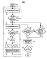
- Fig. 6 is a logic flow diagram of a computer program useful with the present invention.
- a basis polygon 10 represented as a triangle, includes vertices V 1 , V 2 and V 3 .
- this invention is not limited by the shape or number of sides of polygon 10, even though some CIG systems use only convex polygons for avoiding processing ambiguities.
- Polygon 10, including edges 12, 14 and 16 thereof, is used to define features of a scene to be displayed by a CIG system.
- Spatial orthogonal three-axis system polygon descriptors typically referenced to an orthogonal three-axis global system, are stored in a data base having a bulk storage medium, such as magnetic tape or disk.
- the polygon descriptors include x, y, z components of the vertices, along with other information such as color, texture and translucency for each polygon.
- Basis polygon 10 may be considered as a polygon of the lowest or least detailed LOD.
- Polygon 10 includes side 12 extending between vertices V 1 and V 2 , side 14 extending between vertices V 2 and V 3 , and side 16 extending between vertices V 1 and V 3 .
- Breakpoints 22, 24, and 26 may be the mid-points of sides 12, 14 and 16, respectively, or may be a predetermined fixed or random distance from a respective vertex in a clockwise or counterclockwise direction around polygon 10. That is, for a clockwise direction around polygon 10, breakpoint 22 may be determined with respect to V 1 , breakpoint 24 with respect to V 2 and breakpoint 26 with respect to V 3 .
- Fig. 1 Also shown for reference in Fig. 1 are the x and y axes of an orthogonal three-axis coordinate system with the origin at 0. The third or z-axis is perpendicular to the figure at origin 0 and is shown in Fig. 2.
- the x, y and z coordinates of vertices V 1 , V 2 and V 3 from which the x, y and z coordinates of break points 22, 24 and 26 are readily determinable, are available from a data base 60 (Fig. 5).
- the x, y and z coordinates of breakpoint 22 are the average of the sum of the respective x, y and z coordinates of vertices V 1 and V 2 , which are also the end points of side 12 of polygon 10 on which breakpoint 22 lies.
- the x, y and z coordinates for breakpoints 24 and 26 may likewise be determined from the coordinates of V 2 and V 3 for breakpoint 24, and from the coordinates of V 3 and V 1 for breakpoint 26.
- the coordinates of the breakpoint may be readily determined from the coordinates of the vertices of the end points of the side on which the breakpoint lies and the distance of the breakpoint from one of the vertices, using basic algebra, trigonometry and/or analytic geometry.
- processing may include, for example, programming a general purpose computer for determining the equation of a line (side) in three dimensions from the coordinates of the end points (vertices) of the line, and then determining the coordinates of a point (breakpoint) on the line (side) that is disposed at a predetermined distance from one of the end points (vertices) of the line (side).
- Breakpoints 22, 24 and 26 are shown interconnected by a series of dashed lines starting at one breakpoint and proceeding in a clockwise or counterclockwise direction until a closed polygon is obtained.
- FIG. 2 a view looking in the direction of the arrows of line 2-2 of Fig. 1 is shown.
- side 12 and treatment of breakpoint 22 is shown, it being understood that other breakpoints may be treated analogously.
- a deviation or perturbation value dz act is added or subtracted (-dz act ) from the z coordinate value of breakpoint 22 to form a derived vertex 21 when dz act is added to, or a derived vertex 23 when dz act is subtracted from, the z coordinate value of breakpoint 22.
- dz act a deviation or perturbation value
- -dz act a deviation or perturbation value
- breakpoint 22 is added or subtracted (-dz act ) from the z coordinate value of breakpoint 22 to form a derived vertex 21 when dz act is added to, or a derived vertex 23 when dz act is subtracted from, the z coordinate value of breakpoint 22.
- a deviation or perturbation value dz act is added or subtracted (-dz act ) from the z coordinate value of breakpoint 22 to form a derived vertex 21 when dz act is added to, or a derived vertex 23 when dz act is subtracted from, the z coordinate
- dz act dz tlu *K rz *K sz , wherein dz tlu is a base deviation value that may be obtained from a table look-up, K rz is a convergence factor having a value from 0 to 1 that varies continuously as a function of the breakup criteria and K sz is a scaling factor that ensures that the value of dz act does not exceed the value of maximum deviation dz max .
- the value of dz max may be determined in response to the length of the side of a polygon on which the breakpoint being modified is situated for ensuring that the value of dz act presents an acceptable image when displayed, as may be determined by one of ordinary skill in the art without undue experimentation.
- Scaling factor K sz is only required when dz tlu is a random deviation and may be set equal to one for all other cases.
- the value of dz act may be zero. For example, if polygon 10 abuts a cultural feature such as a road, then it may be desirable to supply a deviation dz act of zero to one or more breakpoints to avoid break-up of the cultural feature.
- a vertex created by the addition of dz act to the z coordinate of a breakpoint may be used to represent changes in elevation above a nominal elevation, such as rolling terrain, hills and valleys, while a vertex created by the subtraction of dz act from the z coordinate of a breakpoint may be used to represent relief in the terrain, such as a depression or crater.
- the present invention may be beneficially applied to features that generally do not require specific detail definition, such as terrain and bodies of water, it may be used to generate non-specific fine detail wherever such fine detail may be required or desired, without having to have previously determined or stored the fine detail when statistical data such as random or pseudo-random deviations are used.
- deterministic data that is data representing a specific or generic feature such as mountains, valleys and forests but not necessarily any particular real world feature, can be used to represent highly accurate images of the features.
- Another benefit of the present invention is that as the field of view changes, the fine detail that is generated in accordance with the present invention may be discarded without storing when the feature falls outside the field of view and may be later recreated should the feature again come within the field of view.
- the potential values for dz tlu may be determined and stored in a table look-up to be accessed by a code that is associated with each edge of basis polygon 10 (Fig. 1) and that is stored in the data base. If actual or deterministic data are used then some but not all data must be stored in the data base, such as elevation (z) but not x and y data which may be calculated. The code ensures that the same address is always selected for the edge.
- each dz tlu may be: a random or pseudo-random value; a predetermined constant; derived from real data, such as Defense Mapping Agency data; periodically changing, such as a sinusoidal function, for simulating, for example, waves in a body of water. More important than the actual source of values for dz tlu is that the image ultimately displayed appear to be realistic. It is well within the ability of one of ordinary skill in the art to select the type of deviation and values-or dz tlu that are suited for specific applications in accordance with the teachings of the present invention.
- a perspective view of basis polygon 10 of Fig. 1 having derived vertices in accordance with the present invention is shown.
- Derived vertices 21, and 27 correspond to breakpoints 22, 24, 26 respectively, with respective deviation values added to the z-components thereof.
- New edges 31 and 33 from derived vertex 21, new edges 37 and 38 from derived vertex 25, and new edges 43 and 45 from derived vertex 27 are indicated by dashed lines from the corresponding derived vertex to the end points of the side of basis polygon 10 on which the breakpoint corresponding to the derived vertex lies.
- Derived vertices 21, 25 and 27 are shown interconnected in a clockwise or counterclockwise direction starting with one of the derived vertices by dashed lines 35, 39 and 34 that form the sides of a closed derived polygon having vertices 21, 25 and 27.
- each of four derivative polygons defined by vertex triples V 2 , 21 and 25; V 1 , 21 and 27; V 3 , 25 and 27; 21, 25 and 27, may be processed for forming finer detail than is available from basis polygon 10 for visual images.
- Such processing is analogous to processing which occurs for polygon descriptors that are obtained from the data base.
- the derivative and derived polygons of Fig. 3A may be further subdivided for obtaining even finer detail.
- breakpoints 32, 34 and 36 are indicated on sides 31, 41 and 45 of one of the derivative polygons. Breakpoints may be similarly located on the sides of the other derivative and derived polygons and processing analogous to that used for the initial derived polygon obtained from basis polygon 10 may be employed.
- Point 52 represents a point lying within basis polygon 10.
- Point 52 may lie on an edge of basis polygon 10 if desired which is also considered to be within basis polygon 10.
- a deviation value 54 is combined with coordinate component values of point 52 for locating a derived vertex 56 lying outside the plane of basis polygon 10.
- Derived vertex 10 is shown connected to each vertex V 1 , V 2 and V 3 of basis polygon 10 by dashed lines 51, 53 and 55, respectively.
- Derivative polygons described by vertex triples V 1 , V 2 , 56; V 2 , V 3 , 56 and V 3 , V 1 , 56 may be processed for generating finer detail than is available from processing basis polygon 10. It is noted that when derived vertex 56 is connected to each vertex V 1 , V 2 and V 3 of basis polygon 10 the number of derivative polygons is equal to the number of sides of polygon 10.
- FIG. 4 a schematic diagram not necessarily to scale and including basis polygon 10 subdivided in response to predetermined ranges from a view point in accordance with the present invention is shown.
- a view point 40 is the center of concentric circular range rings 42, 44, 46 and 48, each disposed at a respective greater predetermined distance from viewpoint 40.
- the field of view (FOV) is represented by the smaller angle subtended by the margins 50 of the FOV.
- Basis polygon 10 is shown disposed between range rings 46 and 48. As basis polygon 10 moves toward viewpoint 40 and/or viewpoint 40 moves toward basis polygon 10 so that the relative position between basis polygon 30 and viewpoint 40 changes, and basis polygon 10 is disposed between range rings 44 and 46, additional detail may be required so that a first set of breakpoints for basis polygon 10 are determined. As the distance between basis polygon 10 and viewpoint 40 is further reduced so that basis polygon 10 lies between range rings 42 and 44, more additional detail is provided by determining a second set of breakpoints for the polygons created by the first set of derived vertices corresponding to the initial breakpoints of basis polygon 10 and determining a corresponding second set of derived vertices.
- basis polygon 10 is tested to determine if it lies within a predetermined functional range from viewpoint 40. If basis polygon 10 lies within the functional range, then at least one level of finer detail is allowed to be generated. For each additional level of breakup and resultant finer detail, basis polygon 10 must be within an additional closer range zone to viewpoint 40. In the alternative, an error function interval, such as one for elevation, may be used to determine when additional finer detail is required or permitted.
- a source terrain data such as the Defense Mapping Agency (DMA) supplies data covering large areas having the elevation thereof specified over a predetermined rectangular grid, typically having a spacing of 100 meters between elevation posts. It may be desired to have the elevation of the feature being displayed within a predetermined limit, or error function interval, from the actual elevation provided by the source of data. When the displayed elevation exceeds the error limit or falls outside the error interval then finer detail may be generated.
- DMA Defense Mapping Agency
- Convergence factor K r is used to moderate the introduction of additional detail so that the additional detail is gradually introduced into the scene as the range between viewpoint and basis polygon 10 changes to avoid a sudden appearance of additional detail into a scene.
- a data base 60 has an output connected to an input of a geometry processor 70 for supplying three dimensional polygon descriptors.
- Processor 70 includes an output connected to an input of display processor 80 for receiving two dimensional polygon descriptors from processor 70.
- An output of display processor 80 is connected to a video display 85 for supplying fully processed data that is ultimately displayed by video display 85.
- Detailed description of the operation of these components may be had by reference to U.S. Patents 4,811,245 - Bunker et al. and 4,825,391 - Merz, which are assigned to the present applicants.
- Another output of geometry processor 70 is connected to an input of breakpoint determinator circuitry 90 for receiving polygon descriptor information, while the outputs of breakpoint determinator circuitry 90 are connected to deviation circuitry 100 for supplying breakpoint data.
- Deviation circuitry 100 has outputs respectively connected to other inputs of geometry processor 70 for providing deviation data.
- the deviation data which include coordinates of new vertices as determined in accordance with the present invention, are processed by geometry processor analogously to the information regarding polygon vertices that is received as part of the polygon descriptor data from data base 60.
- Breakpoint data include information regarding the location of a breakpoint on an edge of a polygon with respect to a vertex of the polygon.
- breakpoint data may include information that the breakpoint is to be the midpoint of the edge, a random distance from the vertex, a periodically varying (like sinusoidal) distance from the vertex or other function that may be provided by operator input.
- Deviation circuitry 100, a deviation function selector 102, first scaling means 104, second scaling means 106 and combiner means 108 are connected in series for supplying deviation factor dx act to combiner means 108.
- First and second scaling means 104 and 106 scale the value of the signal provided thereto, such as by multiplying by the constant X rx and K sx , respectively.
- Also supplied to combiner 108 from an output of breakpoint determinator 90 is the coordinate value X bp of the x-coordinate of the breakpoint as determined by breakpoint determinator 90.
- Combiner means 108 combines, such as by adding or subtracting as selected (+/-), the value of the x-component X bp of the breakpoint with the actual deviation dx act from scaler 106 to form the x-component X nv of the coordinates of the new vertex 21 or 23 (Fig. 2).
- the output of combiner 108 which constitutes an output of deviation circuitry 100 and has the x-coordinate X nv of the new vertex is connected to an input of geometry processor 70.
- Analogous circuitry is available in deviation circuitry 100 for producing the y-coordinate Y nv and z-coordinate Z nv for new vertex 21 or 23 (Fig. 2) which are supplied to geometry processor 70.
- step 150 begins at step 150 and executes step 152 to obtain the vertices of the basis polygon.
- step 154 determines if the basis polygon is within the functional range. If it is not, the program returns to step 152. If the polygon is within the functional range, the execution of step 156 determines the breakpoints for each side of the basis polygon.
- Performance of step 158 determines if random deviation is to be used. If it is not to be used then K sz is set equal to one (along with K sx and K sy which are also set equal to one but have not been included in the figure to avoid undue clutter) and then proceeds to step 162. If random deviation is used, the program proceeds to step 162. Execution of step 162 determines the z-coordinate deviation dz act of the new vertex 21 or 23 (Fig. 2). The x- and y- coordinates of a new vertex are determined analogously to z-coordinate dz act but are not illustrated to avoid undue clutter. Performance of step 164 adds the deviation values determined by execution of step 162 to the coordinates of the breakpoint determined at step 156 for obtaining the coordinates of the new vertex.
- step 166 determines if another breakup level of the sides of the polygons defined by the vertices determined at step 164 for creating finer detail is desired. If it is not, then step 168 is performed to process the new polygons for display and execution of step 170 determines if the basis polygon being processed is the last polygon to be processed. If it is, the program ends. If it is not the last polygon, the program returns to step 152, to repeat steps 152 - 170 as described above and step 172, if required, as described below.
- step 172 determines if the basis polygon is within the next level (closer) range ring from the range of step 154. If it is not, then step 168 is performed and processing proceeds as described above. If the basis polygon is within the next level range ring when step 172 is performed, then step 156 is executed to determine the breakpoints of the polygon defined by the vertices determined at the last performance of step 164. Steps 156-172 are repeated as required until testing at step 170 indicates that the last polygon has been processed.
Landscapes
- Engineering & Computer Science (AREA)
- Computer Graphics (AREA)
- Physics & Mathematics (AREA)
- General Physics & Mathematics (AREA)
- Theoretical Computer Science (AREA)
- Image Generation (AREA)
- Processing Or Creating Images (AREA)
Description
- This invention relates to spatial augmentation of vertices for level of detail transition, and, more particularly, to a method for obtaining smooth transformation between effective levels of detail by creating new vertices in response to predetermined data descriptors.
- Typically, objects to be displayed in a scene of a computer image generation (CIG) system are represented by edges of polygons, or faces, the vertex descriptors of which are stored in a data base. Some form of transition between levels of detail (LOD's) for representing objects to be displayed in CIG systems is also generally used. LOD's enable objects that are more distant from a viewpoint to be represented by fewer edges or polygons, thereby conserving computing resources for closer objects which typically require more detail and correspondingly more edges in order to be accurately and realistically represented. Transitions between LOD's occur at respective predetermined ranges, or zones or regions, from a viewpoint with each lower, or more distant LOD, having correspondingly fewer edges assigned to corresponding features and therefore less detail for objects to be displayed.
- In early CIG systems, transition from one LOD to another LOD occurred at respective predetermined ranges from a viewpoint and would be abrupt when the predetermined range was reached. Inasmuch as the human perception system is very sensitive to abrupt transition, this effect during image presentation was distracting and detracted from the goal of achieving realism.
- Such a CIG system is known from US-A-4 646 251 where a parallel processor arrangement is used for a fast computation of refined control points from an initial control point distribution, thereby qenerating a refined polygon structure. The process of US-A-5 646 251 is recursive so that further levels of subdivision expeditiously lead to greater refinement of the generated image.
- The development of translucent face capability for CIG systems made possible a significant improvement in implementation of transitions between LOD's. For example, an LOD transition translucency control factor applicable to each LOD at the transition zone between adjacent LOD's, and that monotonically increases from 0 to 1 (0 percent to 100 percent) at a predetermined rate in response to the change in range as an observer moves toward a scene can be used to control the translucency of faces from from adjacent LOD's. The translucency control factor determines the translucency of a face, from opaque at 0 to transparent at 1 with proportionate fractional values of translucency in between. At the proximate boundary of the transition zone the coarse terrain faces of the lower detail LOD are opaque (control factor = 0) and the fine terrain faces of the higher detail LOD are transparent (control factor = 1). Continuing across the transition zone, a point is reached at which the coarse LOD faces have a translucency of x, say 25%, and the fine LOD faces have a translucency of (1-x) say 75%. In progressing through the transition zone, some point will be reached at which the coarse and fine LOD faces each have a translucency of 50%. At the remote boundary of the transition zone the fine LOD faces will be transparent and the coarse LOD faces will be opaque.
- Although translucency blending during LOD transition is an improvement over abrupt switching of LOD information, there are still cases where translucency blending does not provide accurate and/or unambiguous results. For instance, if the fine LOD contains a peak of terrain that extends above the terrain of the coarse LOD and a feature, such as a vehicle, is spatially defined to be behind the peak of fine terrain, then at the 50-50 percent of translucency transition, the scene will show the feature as a blend of 50% feature definition (faces) and 50% terrain definition (faces), thus making the feature appear to be in front of the terrain even though spatially it was defined to be behind the terrain. This effect is known as bleedthrough.
- In another example, it is sometimes required to determine when a collision between objects occurs. If, for example a vehicle is represented by faces with one percent translucency and a feature that is a potential target for a collision is represented by 99 percent translucency, then although the feature will not be visible to the observer, a collision between the vehicle and the feature will be detected.
- Other potential deficiencies include inability to provide a face from either one LOD or the other that validly represents vehicle position and attitude at all points in the transition zone between LOD's, and inefficiency in computer processing because all faces in the transition zone from both LOD's must be processed to determine proper assignment of subpixel color and texture modulation for ultimate display.
- It would be desirable to provide a method for overcoming position, attitude and collision ambiguities, bleedthrough effects, subpixel processing inefficiencies caused by having multiple polygon groups (one from each adjacent LOD) representing a single object, and other deficiencies that may be associated with prior CIG systems during LOD transitions. In addition it would be desirable to achieve smooth LOD transition without resort to translucency blending.
- Accordingly, there is disclosed herein a method for eliminating position, attitude and collision ambiguities, bleedthrough effects, subpixel processing inefficiencies caused by having multiple polygon groups representing a single object, and other deficiencies that may be associated with prior CIG systems caused by LOD transitions during image presentation.The method provides for creating desired finer detail from predefined coarser data for effective smooth LOD transitions, without resort to translucency blending. Smooth LOD transition is achieved by generating finer detail than is available from predefined data without having to predefine and/or store most of the finer detail.
- The invention is set out in
claims 1 and 17. - The invention, both as to organization and method of operation, together with further objectives and advantages thereof, may best be understood by reference to the detailed description taken in connection with the accompanying drawing, in which:
- Fig. 1 is plan view of a basis polygon subdivided in accordance with the present invention.
- Fig. 2 is a representative edge of the polygon of Fig. 1 looking in the direction of the arrows of line 2-2 referenced to an xyz orthogonal axis system and including a deviation factor for forming additional vertices in accordance with the present invention.
- Figs. 3A and 3B are a perspective view of the basis polygon of Fig. 1 showing derived vertices in accordance with the present invention.
- Fig. 4 is a schematic diagram of the basis polygon of Fig. 1 subdivided in response to predetermined ranges from a viewpoint in accordance with the present invention.
- Fig. 5 is a hardware block diagram in accordance with the present invention.
- Fig. 6 is a logic flow diagram of a computer program useful with the present invention.
- Referring to Fig. 1, a
basis polygon 10, represented as a triangle, includes vertices V1, V2 and V3. Of course, this invention is not limited by the shape or number of sides ofpolygon 10, even though some CIG systems use only convex polygons for avoiding processing ambiguities.Polygon 10, includingedges -
Basis polygon 10 may be considered as a polygon of the lowest or least detailed LOD.Polygon 10 includesside 12 extending between vertices V1 and V2,side 14 extending between vertices V2 and V3, andside 16 extending between vertices V1 and V3. Breakpoints 22, 24, and 26 may be the mid-points ofsides polygon 10. That is, for a clockwise direction aroundpolygon 10,breakpoint 22 may be determined with respect to V1,breakpoint 24 with respect to V2 andbreakpoint 26 with respect to V3. - Also shown for reference in Fig. 1 are the x and y axes of an orthogonal three-axis coordinate system with the origin at 0. The third or z-axis is perpendicular to the figure at origin 0 and is shown in Fig. 2. The x, y and z coordinates of vertices V1, V2 and V3, from which the x, y and z coordinates of
break points breakpoint 22 constitutes the midpoint ofside 12, then the x, y and z coordinates ofbreakpoint 22 are the average of the sum of the respective x, y and z coordinates of vertices V1 and V2, which are also the end points ofside 12 ofpolygon 10 on whichbreakpoint 22 lies. The x, y and z coordinates forbreakpoints breakpoint 24, and from the coordinates of V3 and V1 forbreakpoint 26. - When a breakpoint is not the mid-point of a side of a polygon, the coordinates of the breakpoint may be readily determined from the coordinates of the vertices of the end points of the side on which the breakpoint lies and the distance of the breakpoint from one of the vertices, using basic algebra, trigonometry and/or analytic geometry. Such processing may include, for example, programming a general purpose computer for determining the equation of a line (side) in three dimensions from the coordinates of the end points (vertices) of the line, and then determining the coordinates of a point (breakpoint) on the line (side) that is disposed at a predetermined distance from one of the end points (vertices) of the line (side).
-
Breakpoints - Referring to Fig. 2, a view looking in the direction of the arrows of line 2-2 of Fig. 1 is shown. For convenience and to avoid undue repetition and clutter, only
side 12 and treatment ofbreakpoint 22 is shown, it being understood that other breakpoints may be treated analogously. - As shown in Fig. 2, a deviation or perturbation value dzact is added or subtracted (-dzact) from the z coordinate value of
breakpoint 22 to form aderived vertex 21 when dzact is added to, or aderived vertex 23 when dzact is subtracted from, the z coordinate value ofbreakpoint 22. In the example shown, only the z coordinate ofbreakpoint 22 is modified, it being recognizable by one of ordinary skill in the art that any combination or permutation of modifications to the x, y and z components of each breakpoint independent of the modifications applied to each other breakpoint may be performed as desired in accordance with the teachings of the present invention for forming derived vertices. Thus,vertices breakpoint 22 with the z component modified by the value of dzact. - The value of dzact may be determined in accordance with the following equation:

polygon 10 abuts a cultural feature such as a road, then it may be desirable to supply a deviation dzact of zero to one or more breakpoints to avoid break-up of the cultural feature. - Inasmuch as the z-axis is generally defined to be vertical with the x and y axes perpendicular thereto and to each other as well, a vertex created by the addition of dzact to the z coordinate of a breakpoint may be used to represent changes in elevation above a nominal elevation, such as rolling terrain, hills and valleys, while a vertex created by the subtraction of dzact from the z coordinate of a breakpoint may be used to represent relief in the terrain, such as a depression or crater.
- It is noted that regardless of whether the value of dzact is added to, or subtracted from, the z component of
breakpoint 22,new vertex new edges 31 and 33, or two new edges 47 and 49, respectively, as indicated by dashed lines fromnew vertex edge 12 are obtained without having been previously defined or stored. Further, it is possible to determine the coordinate values ofnew vertices breakpoint 22 also removes the derived polygon as determined bybreakpoints - Although the present invention may be beneficially applied to features that generally do not require specific detail definition, such as terrain and bodies of water, it may be used to generate non-specific fine detail wherever such fine detail may be required or desired, without having to have previously determined or stored the fine detail when statistical data such as random or pseudo-random deviations are used. In addition, deterministic data, that is data representing a specific or generic feature such as mountains, valleys and forests but not necessarily any particular real world feature, can be used to represent highly accurate images of the features. Another benefit of the present invention is that as the field of view changes, the fine detail that is generated in accordance with the present invention may be discarded without storing when the feature falls outside the field of view and may be later recreated should the feature again come within the field of view.
- The potential values for dztlu may be determined and stored in a table look-up to be accessed by a code that is associated with each edge of basis polygon 10 (Fig. 1) and that is stored in the data base. If actual or deterministic data are used then some but not all data must be stored in the data base, such as elevation (z) but not x and y data which may be calculated. The code ensures that the same address is always selected for the edge. According to the type of terrain or feature being simulated, the value of each dztlu may be: a random or pseudo-random value; a predetermined constant; derived from real data, such as Defense Mapping Agency data; periodically changing, such as a sinusoidal function, for simulating, for example, waves in a body of water. More important than the actual source of values for dztlu is that the image ultimately displayed appear to be realistic. It is well within the ability of one of ordinary skill in the art to select the type of deviation and values-or dztlu that are suited for specific applications in accordance with the teachings of the present invention.
- Referring to Fig. 3A, a perspective view of
basis polygon 10 of Fig. 1 having derived vertices in accordance with the present invention is shown. Derivedvertices - New edges 31 and 33 from derived
vertex 21, new edges 37 and 38 from derived vertex 25, andnew edges 43 and 45 from derivedvertex 27 are indicated by dashed lines from the corresponding derived vertex to the end points of the side ofbasis polygon 10 on which the breakpoint corresponding to the derived vertex lies. Derivedvertices lines polygon having vertices basis polygon 10 for visual images. Such processing is analogous to processing which occurs for polygon descriptors that are obtained from the data base. - If desired, the derivative and derived polygons of Fig. 3A may be further subdivided for obtaining even finer detail. For instance, breakpoints 32, 34 and 36 are indicated on sides 31, 41 and 45 of one of the derivative polygons. Breakpoints may be similarly located on the sides of the other derivative and derived polygons and processing analogous to that used for the initial derived polygon obtained from
basis polygon 10 may be employed. - Referring to Fig. 3B, another embodiment for augmenting vertices in accordance with the present invention is shown. Point 52 represents a point lying within
basis polygon 10. Point 52 may lie on an edge ofbasis polygon 10 if desired which is also considered to be withinbasis polygon 10. Adeviation value 54 is combined with coordinate component values of point 52 for locating a derivedvertex 56 lying outside the plane ofbasis polygon 10. Derivedvertex 10 is shown connected to each vertex V1, V2 and V3 ofbasis polygon 10 by dashedlines basis polygon 10. It is noted that when derivedvertex 56 is connected to each vertex V1, V2 and V3 ofbasis polygon 10 the number of derivative polygons is equal to the number of sides ofpolygon 10. - Referring to Fig. 4, a schematic diagram not necessarily to scale and including
basis polygon 10 subdivided in response to predetermined ranges from a view point in accordance with the present invention is shown. - A
view point 40 is the center of concentric circular range rings 42, 44, 46 and 48, each disposed at a respective greater predetermined distance fromviewpoint 40. The field of view (FOV) is represented by the smaller angle subtended by themargins 50 of the FOV. -
Basis polygon 10 is shown disposed between range rings 46 and 48. Asbasis polygon 10 moves towardviewpoint 40 and/orviewpoint 40 moves towardbasis polygon 10 so that the relative position between basis polygon 30 andviewpoint 40 changes, andbasis polygon 10 is disposed between range rings 44 and 46, additional detail may be required so that a first set of breakpoints forbasis polygon 10 are determined. As the distance betweenbasis polygon 10 andviewpoint 40 is further reduced so thatbasis polygon 10 lies between range rings 42 and 44, more additional detail is provided by determining a second set of breakpoints for the polygons created by the first set of derived vertices corresponding to the initial breakpoints ofbasis polygon 10 and determining a corresponding second set of derived vertices. The process of locating breakpoints and creating new vertices for augmenting the number of predetermined vertices available in a CIG system may be repeated as desired. Creation of additional scene detail in accordance with the present invention provides continuous transition between LOD's without resort to blending so that only one group of polygons is processed, thereby avoiding ambiguities and inefficiencies previously referred to. - However, even if desired, it may not be economical from the standpoint of allocating limited computing resources to generate such finer detail. For instance, if an object is beyond a predetermined distance from the viewpoint, the finer detail will not be viewable to an observer and there is no need to generate it. Thus, before finer detail is generated,
basis polygon 10 is tested to determine if it lies within a predetermined functional range fromviewpoint 40. Ifbasis polygon 10 lies within the functional range, then at least one level of finer detail is allowed to be generated. For each additional level of breakup and resultant finer detail,basis polygon 10 must be within an additional closer range zone toviewpoint 40. In the alternative, an error function interval, such as one for elevation, may be used to determine when additional finer detail is required or permitted. - A source terrain data, such as the Defense Mapping Agency (DMA) supplies data covering large areas having the elevation thereof specified over a predetermined rectangular grid, typically having a spacing of 100 meters between elevation posts. It may be desired to have the elevation of the feature being displayed within a predetermined limit, or error function interval, from the actual elevation provided by the source of data. When the displayed elevation exceeds the error limit or falls outside the error interval then finer detail may be generated.
- Another alternative, regardless of the source of data, is to increase the amount of detail within the scene as the angle within a
view window boresight 58 and a view ray 59 to a predetermined point, such as the centroid, ofbasis polygon 10 decreases. Fine detail may be generated only when the angle betweenview window boresight 58 and view ray 59 is less than a predetermined threshold value. This would permit efficient use of computing resources when a system such as an eye-tracked area of interest display is used. As illustrated in Fig. 4,basis polygon 10 that is intersected by view ray 59 is disposed in the peripheral region outside threshold angular limit value 57 and thus is not subdivided even though it would be subdivided if a range test would be used. A combination of sub-dividing criteria may be used for determining when subdivision ofbasis polygon 10 is appropriate. - Convergence factor Kr is used to moderate the introduction of additional detail so that the additional detail is gradually introduced into the scene as the range between viewpoint and
basis polygon 10 changes to avoid a sudden appearance of additional detail into a scene. - Referring to Fig. 5, a hardware block diagram in accordance with the present invention is shown. A
data base 60 has an output connected to an input of ageometry processor 70 for supplying three dimensional polygon descriptors.Processor 70 includes an output connected to an input ofdisplay processor 80 for receiving two dimensional polygon descriptors fromprocessor 70. An output ofdisplay processor 80 is connected to avideo display 85 for supplying fully processed data that is ultimately displayed byvideo display 85. Detailed description of the operation of these components may be had by reference to U.S. Patents 4,811,245 - Bunker et al. and 4,825,391 - Merz, which are assigned to the present applicants. - Another output of
geometry processor 70 is connected to an input ofbreakpoint determinator circuitry 90 for receiving polygon descriptor information, while the outputs ofbreakpoint determinator circuitry 90 are connected todeviation circuitry 100 for supplying breakpoint data.Deviation circuitry 100 has outputs respectively connected to other inputs ofgeometry processor 70 for providing deviation data. The deviation data, which include coordinates of new vertices as determined in accordance with the present invention, are processed by geometry processor analogously to the information regarding polygon vertices that is received as part of the polygon descriptor data fromdata base 60. - Another input of
breakpoint determinator 90 is connected for receiving breakpoint data. Breakpoint data include information regarding the location of a breakpoint on an edge of a polygon with respect to a vertex of the polygon. For example, breakpoint data may include information that the breakpoint is to be the midpoint of the edge, a random distance from the vertex, a periodically varying (like sinusoidal) distance from the vertex or other function that may be provided by operator input. -
Deviation circuitry 100, adeviation function selector 102, first scaling means 104, second scaling means 106 and combiner means 108 are connected in series for supplying deviation factor dxact to combiner means 108. First and second scaling means 104 and 106 scale the value of the signal provided thereto, such as by multiplying by the constant Xrx and Ksx, respectively. Also supplied tocombiner 108 from an output ofbreakpoint determinator 90 is the coordinate value Xbp of the x-coordinate of the breakpoint as determined bybreakpoint determinator 90. Combiner means 108 combines, such as by adding or subtracting as selected (+/-), the value of the x-component Xbp of the breakpoint with the actual deviation dxact fromscaler 106 to form the x-component Xnv of the coordinates of thenew vertex 21 or 23 (Fig. 2). The output ofcombiner 108, which constitutes an output ofdeviation circuitry 100 and has the x-coordinate Xnv of the new vertex is connected to an input ofgeometry processor 70. Analogous circuitry is available indeviation circuitry 100 for producing the y-coordinate Ynv and z-coordinate Znv fornew vertex 21 or 23 (Fig. 2) which are supplied togeometry processor 70. - Referring to Fig. 6, a flow diagram useful for programming a general purpose computer in accordance with the present invention is shown. The program begins at
step 150 and executes step 152 to obtain the vertices of the basis polygon. Performance ofstep 154 determines if the basis polygon is within the functional range. If it is not, the program returns to step 152. If the polygon is within the functional range, the execution ofstep 156 determines the breakpoints for each side of the basis polygon. - Performance of
step 158 determines if random deviation is to be used. If it is not to be used then Ksz is set equal to one (along with Ksx and Ksy which are also set equal to one but have not been included in the figure to avoid undue clutter) and then proceeds to step 162. If random deviation is used, the program proceeds to step 162. Execution ofstep 162 determines the z-coordinate deviation dzact of thenew vertex 21 or 23 (Fig. 2). The x- and y- coordinates of a new vertex are determined analogously to z-coordinate dzact but are not illustrated to avoid undue clutter. Performance ofstep 164 adds the deviation values determined by execution ofstep 162 to the coordinates of the breakpoint determined atstep 156 for obtaining the coordinates of the new vertex. - Execution of
step 166 determines if another breakup level of the sides of the polygons defined by the vertices determined atstep 164 for creating finer detail is desired. If it is not, then step 168 is performed to process the new polygons for display and execution ofstep 170 determines if the basis polygon being processed is the last polygon to be processed. If it is, the program ends. If it is not the last polygon, the program returns to step 152, to repeat steps 152 - 170 as described above and step 172, if required, as described below. - If another breakup level is desired when
step 166 is performed, then execution ofstep 172 determines if the basis polygon is within the next level (closer) range ring from the range ofstep 154. If it is not, then step 168 is performed and processing proceeds as described above. If the basis polygon is within the next level range ring whenstep 172 is performed, then step 156 is executed to determine the breakpoints of the polygon defined by the vertices determined at the last performance ofstep 164. Steps 156-172 are repeated as required until testing atstep 170 indicates that the last polygon has been processed. - Thus has been illustrated and described a method for eliminating position, attitude and collision ambiguities, bleedthrough effects, subpixel processing inefficiencies caused by having multiple polygon groups representing a single object, and other deficiencies that may be associated with prior CIG systems caused by LOD transitions during image presentation. Also shown and described is a method for creating finer detail from predefined coarser data without having to predefine and/or store most of the finer detail and without resort to translucency blending for achieving smooth LOD transition. A method for achieving smooth LOD transition by generating finer detail than is available from predefined data without having to predefine and/or store the finer detail is also illustrated and described.
Claims (19)
- A method for achieving substantially continuous smooth level of detail transition in a computer image generation system wherein object features of a display image are formed by first planar polygons, each having a plurality of first vertices each designating one end point of each side of one of the first polygons, the method comprising the steps of:(a) retrieving from storage data determining each of the first vertices of each of the first polygons;(b) separating each of at least some of the first polygons into a plurality of planar second polygons, each smaller than the associated first polygon, with each second polygon having at least one second vertex which is located at a juncture formed by two sides of that second polygon and with each second vertex being different from any one of the first vertices;(c) locating, for at least one selected one of the second vertices, a corresponding derived third vertex lying some deviational amount outside the common plane of the associated first and second polygons and different from any of the stored first vertices;(d) displaying at least one derived planar polygon, each defined by a different combination of one of a third vertex determined in step (c) and associated ones of the first and second vertices, to create and display at least some of a sequence of scenes of a viewable image; and(e) varying the deviational amount in a manner to display scenes having an increasing level of detail as a viewpoint nears a polygon location, and with a substantially continuous smooth level of detail transition.
- The method of claim 1, wherein each second vertex has an elevation component associated therewith, and step (c) includes the step of locating at least one of the third vertices such that the elevation data component of that third vertex is different from the elevation data component of its associated second vertex.
- The method of claim 2, wherein the elevation data component of the selected third vertex is greater than the elevation data component of its associated second vertex.
- The method of claim 3, wherein the elevation data component of the selected third vertex is less than the elevation data component of its associated second vertex.
- The method of claim 1, wherein step (b) includes the step of breaking up at least some of the first polygons into second polygons only when an angle, between an image viewpoint and both a boresight of a view window and a view ray to that one of the first polygons, is within a predetermined limit.
- The method of claim 1, wherein each polygon is a triangle.
- The method of claim 1, wherein the breakpoints and the derived vertices are described in a mutually-orthogonal three-axis system, and step (c) includes the steps of:(c1) obtaining deviation value data for each breakpoint; and(c2) combining deviation value data obtained for a particular breakpoint with data for an axis coordinate of the breakpoint to obtain data establishing the actual coordinate of the derived vertex along that same axis.
- The method of claim 7, wherein the combining step (c2) includes the step of adding an associated deviation data value to each of at least one different one of the three axial data values of the orthogonal three-axis system used to identify breakpoint position.
- The method of claim 7, wherein the combining step (c2) includes the step of subtracting an associated deviation data value from each of at least one different one of the three axial data values of the orthogonal three-axis system used to identify breakpoint position.
- The method of claim 7, wherein the deviation amount is selected from the group consisting of:predetermined constant values;random values;predetermined sinusoidal values;other predetermined periodic values;terrain geospecific values;and a combination of these values.
- The method of claim 1, wherein step (c) includes the step of designating each different third vertex to be a predetermined distance along a different preselected side extending from an associated preselected vertex of the basis polygon.
- The method of claim 11, wherein the predetermined distance is selected from the group consisting of:one-half the length of the corresponding side;a predetermined constant distance; a random distance; and a combination of these distances.
- The method of claim 1, whereinstep (c) further includes the step (c) of processing the total data to determine other breakpoints, each other breakpoint lying on a corresponding side of the derived polygon;step (d) further includes the step (d') of substantially continuously modifying data for at least one of the other breakpoints to form data designating another derived vertex which lies outside the plane of both the derived polygon and the basis polygon; andstep (e) further includes the step (e') of including the other derived vertex data in the augmented vertex data.
- The method of claim 13, whereinstep (c) is performed only when the basis polygon is within a first predetermined distance from the viewpoint; and thestep (c') of processing data to determine other breakpoints is performed only when the involved polygon is within a second predetermined distance, closer to the view point than the first predetermined distance.
- The method of claim 1, wherein step (c) is performed only when the basis polygon is within a predetermined distance from the viewpoint.
- The method of claim 1, wherein
step (c) further includes the step of determining said at least one breakpoint only when an angle between a boresight of a view window and a view ray to the involved polygon, both with respect to the view point, is within a predetermined limit. - An augmentation method for a computer image generation system wherein object features of an image to be displayed are represented by planar basis polygons having vertices designating end points of each of a plurality of sides of the basis polygons, the method being for augmenting a total number of vertices to cause an increased number of total polygons, each with finer detail for the object features, to be displayed with substantially continuous smooth level of detail transition in viewable scenes created by the system, and comprising the steps of:(a) retrieving from storage vertex data defining each of a plurality of the basis polygons;(b) selecting a point lying within each of at least one selected one of the basis polygons and different from any vertex of the associated basis polygon;(c) locating a derived vertex lying at a deviation distance outside the plane of the associated basis polygon at the selected point and different from any of the stored basis polygon vertices;(d) forming at least one derived polygon determined by the derived vertex and at least two adjacent vertices of the associated basis polygon, responsive to the location of the associated basis polygon nearing an observer viewpoint in the image; and(e) displaying the derived polygon as part of the viewable image of a scene having finer feature detail along with substantially continuous smooth level of detail transition as the polygon location distance to the viewpoint decreases.
- The method of claim 17, wherein step (e) includes the steps of:forming a plurality of derived polygons each including the derived vertex and a side of the associated basis polygon, with the plurality of derived polygons equal in number to the number of sides of the basis polygon;and displaying the plurality of derived polygons to obtain the display image.
- The method of claim 17, wherein step (b) further includes the step of selecting each basis polygon point only when an angle, formed between the image view point and both a boresight of a view window and a view ray to the basis polygon, is within a predetermined limit.
Applications Claiming Priority (2)
| Application Number | Priority Date | Filing Date | Title |
|---|---|---|---|
| US37768789A | 1989-07-10 | 1989-07-10 | |
| US377687 | 1989-07-10 |
Publications (3)
| Publication Number | Publication Date |
|---|---|
| EP0408232A2 EP0408232A2 (en) | 1991-01-16 |
| EP0408232A3 EP0408232A3 (en) | 1992-09-23 |
| EP0408232B1 true EP0408232B1 (en) | 1997-12-10 |
Family
ID=23490135
Family Applications (1)
| Application Number | Title | Priority Date | Filing Date |
|---|---|---|---|
| EP90307232A Expired - Lifetime EP0408232B1 (en) | 1989-07-10 | 1990-07-02 | Spatial augmentation of vertices for level of detail transition |
Country Status (6)
| Country | Link |
|---|---|
| EP (1) | EP0408232B1 (en) |
| JP (1) | JP2852813B2 (en) |
| CA (1) | CA2020550A1 (en) |
| DE (1) | DE69031789T2 (en) |
| IL (1) | IL94890A (en) |
| WO (1) | WO1991001529A1 (en) |
Families Citing this family (1)
| Publication number | Priority date | Publication date | Assignee | Title |
|---|---|---|---|---|
| JP2002279449A (en) * | 2001-03-19 | 2002-09-27 | Mitsubishi Electric Corp | Three-dimensional spatial data transmission display device, three-dimensional spatial data transmission method, computer-readable recording medium storing a program for causing a computer to execute the three-dimensional spatial data transmission method |
Family Cites Families (7)
| Publication number | Priority date | Publication date | Assignee | Title |
|---|---|---|---|---|
| US4291380A (en) * | 1979-05-14 | 1981-09-22 | The Singer Company | Resolvability test and projection size clipping for polygon face display |
| IL72685A (en) * | 1983-08-30 | 1988-08-31 | Gen Electric | Advanced video object generator |
| US4715005A (en) * | 1984-08-08 | 1987-12-22 | General Electric Company | Terrain/seascape image generator with math model data base |
| US4821212A (en) * | 1984-08-08 | 1989-04-11 | General Electric Company | Three dimensional texture generator for computed terrain images |
| US4646251A (en) * | 1985-10-03 | 1987-02-24 | Evans & Sutherland Computer Corporation | Computer graphics, parametric patch parallel subdivision processor |
| US4912664A (en) * | 1988-02-01 | 1990-03-27 | Mentor Graphics Corporation | Method and apparatus for generating a mesh for finite element analysis |
| US4933889A (en) * | 1988-04-29 | 1990-06-12 | International Business Machines Corporation | Method for fine decomposition in finite element mesh generation |
-
1990
- 1990-06-22 WO PCT/US1990/003567 patent/WO1991001529A1/en not_active Ceased
- 1990-06-22 JP JP3500351A patent/JP2852813B2/en not_active Expired - Lifetime
- 1990-06-27 IL IL9489090A patent/IL94890A/en active IP Right Grant
- 1990-07-02 DE DE69031789T patent/DE69031789T2/en not_active Expired - Fee Related
- 1990-07-02 EP EP90307232A patent/EP0408232B1/en not_active Expired - Lifetime
- 1990-07-05 CA CA002020550A patent/CA2020550A1/en not_active Abandoned
Also Published As
| Publication number | Publication date |
|---|---|
| DE69031789D1 (en) | 1998-01-22 |
| JPH04500878A (en) | 1992-02-13 |
| DE69031789T2 (en) | 1998-07-02 |
| EP0408232A3 (en) | 1992-09-23 |
| CA2020550A1 (en) | 1991-01-11 |
| IL94890A0 (en) | 1991-04-15 |
| WO1991001529A1 (en) | 1991-02-07 |
| IL94890A (en) | 1995-12-31 |
| JP2852813B2 (en) | 1999-02-03 |
| EP0408232A2 (en) | 1991-01-16 |
Similar Documents
| Publication | Publication Date | Title |
|---|---|---|
| US5367615A (en) | Spatial augmentation of vertices and continuous level of detail transition for smoothly varying terrain polygon density | |
| Appel et al. | The haloed line effect for hidden line elimination. | |
| US5841441A (en) | High-speed three-dimensional texture mapping systems and methods | |
| KR910009101B1 (en) | Image Synthesis Device | |
| US5630718A (en) | Weather simulation system | |
| JP2667835B2 (en) | Computer Graphics Display | |
| US4855934A (en) | System for texturing computer graphics images | |
| US3602702A (en) | Electronically generated perspective images | |
| US4291380A (en) | Resolvability test and projection size clipping for polygon face display | |
| US5598359A (en) | Weather effects generator for simulation systems | |
| JP3759971B2 (en) | How to shade a 3D image | |
| EP0137107A1 (en) | A computer generated imagery system | |
| US5409379A (en) | Weather simulation system | |
| US4179824A (en) | Simulation of an object system formed by polygon faces having a series of fundamental shapes and dimension | |
| GB2243523A (en) | Generating elliptical objects | |
| GB2226219A (en) | Method for three-dimensional clip checking for computer graphics | |
| US6822658B1 (en) | Rendering a silhouette edge | |
| EP0314368B1 (en) | Method and apparatus for hidden surface removal | |
| US5664077A (en) | Three-dimensional graph displaying system | |
| EP0408232A2 (en) | Spatial augmentation of vertices for level of detail transition | |
| US6590582B1 (en) | Clipping processing method | |
| GB2238215A (en) | Computer display system with a three dimensional cursor shadow | |
| EP0250588B1 (en) | Comprehensive distortion correction in a real time imaging system | |
| CA2065736C (en) | Spatial augmentation of vertices and continuous level of detail transition for smoothly varying terrain polygon density | |
| JP2952585B1 (en) | Image generation method |
Legal Events
| Date | Code | Title | Description |
|---|---|---|---|
| PUAI | Public reference made under article 153(3) epc to a published international application that has entered the european phase |
Free format text: ORIGINAL CODE: 0009012 |
|
| AK | Designated contracting states |
Kind code of ref document: A2 Designated state(s): DE FR GB IT |
|
| PUAL | Search report despatched |
Free format text: ORIGINAL CODE: 0009013 |
|
| AK | Designated contracting states |
Kind code of ref document: A3 Designated state(s): DE FR GB IT |
|
| 17P | Request for examination filed |
Effective date: 19930318 |
|
| 17Q | First examination report despatched |
Effective date: 19950905 |
|
| GRAG | Despatch of communication of intention to grant |
Free format text: ORIGINAL CODE: EPIDOS AGRA |
|
| GRAG | Despatch of communication of intention to grant |
Free format text: ORIGINAL CODE: EPIDOS AGRA |
|
| GRAH | Despatch of communication of intention to grant a patent |
Free format text: ORIGINAL CODE: EPIDOS IGRA |
|
| GRAH | Despatch of communication of intention to grant a patent |
Free format text: ORIGINAL CODE: EPIDOS IGRA |
|
| GRAA | (expected) grant |
Free format text: ORIGINAL CODE: 0009210 |
|
| AK | Designated contracting states |
Kind code of ref document: B1 Designated state(s): DE FR GB IT |
|
| ET | Fr: translation filed | ||
| REF | Corresponds to: |
Ref document number: 69031789 Country of ref document: DE Date of ref document: 19980122 |
|
| ITF | It: translation for a ep patent filed | ||
| PLBE | No opposition filed within time limit |
Free format text: ORIGINAL CODE: 0009261 |
|
| STAA | Information on the status of an ep patent application or granted ep patent |
Free format text: STATUS: NO OPPOSITION FILED WITHIN TIME LIMIT |
|
| 26N | No opposition filed | ||
| REG | Reference to a national code |
Ref country code: GB Ref legal event code: IF02 |
|
| REG | Reference to a national code |
Ref country code: GB Ref legal event code: 732E |
|
| REG | Reference to a national code |
Ref country code: GB Ref legal event code: 732E |
|
| REG | Reference to a national code |
Ref country code: GB Ref legal event code: 732E |
|
| REG | Reference to a national code |
Ref country code: FR Ref legal event code: TP |
|
| PGFP | Annual fee paid to national office [announced via postgrant information from national office to epo] |
Ref country code: DE Payment date: 20070831 Year of fee payment: 18 |
|
| PGFP | Annual fee paid to national office [announced via postgrant information from national office to epo] |
Ref country code: GB Payment date: 20070727 Year of fee payment: 18 |
|
| PGFP | Annual fee paid to national office [announced via postgrant information from national office to epo] |
Ref country code: IT Payment date: 20070730 Year of fee payment: 18 |
|
| PGFP | Annual fee paid to national office [announced via postgrant information from national office to epo] |
Ref country code: FR Payment date: 20070717 Year of fee payment: 18 |
|
| GBPC | Gb: european patent ceased through non-payment of renewal fee |
Effective date: 20080702 |
|
| PG25 | Lapsed in a contracting state [announced via postgrant information from national office to epo] |
Ref country code: DE Free format text: LAPSE BECAUSE OF NON-PAYMENT OF DUE FEES Effective date: 20090203 |
|
| REG | Reference to a national code |
Ref country code: FR Ref legal event code: ST Effective date: 20090331 |
|
| PG25 | Lapsed in a contracting state [announced via postgrant information from national office to epo] |
Ref country code: GB Free format text: LAPSE BECAUSE OF NON-PAYMENT OF DUE FEES Effective date: 20080702 |
|
| PG25 | Lapsed in a contracting state [announced via postgrant information from national office to epo] |
Ref country code: IT Free format text: LAPSE BECAUSE OF NON-PAYMENT OF DUE FEES Effective date: 20080702 Ref country code: FR Free format text: LAPSE BECAUSE OF NON-PAYMENT OF DUE FEES Effective date: 20080731 |