EP0407966B1 - Réceptacle amovible pour pile, en particulier pour pile-bouton - Google Patents
Réceptacle amovible pour pile, en particulier pour pile-bouton Download PDFInfo
- Publication number
- EP0407966B1 EP0407966B1 EP90113153A EP90113153A EP0407966B1 EP 0407966 B1 EP0407966 B1 EP 0407966B1 EP 90113153 A EP90113153 A EP 90113153A EP 90113153 A EP90113153 A EP 90113153A EP 0407966 B1 EP0407966 B1 EP 0407966B1
- Authority
- EP
- European Patent Office
- Prior art keywords
- holder
- retaining
- receptacle
- opening
- receiving
- Prior art date
- Legal status (The legal status is an assumption and is not a legal conclusion. Google has not performed a legal analysis and makes no representation as to the accuracy of the status listed.)
- Expired - Lifetime
Links
- 229920003023 plastic Polymers 0.000 claims abstract description 6
- 239000004033 plastic Substances 0.000 claims abstract description 6
- 239000000463 material Substances 0.000 claims abstract description 4
- 238000000605 extraction Methods 0.000 claims description 11
- 238000010276 construction Methods 0.000 claims 2
- 240000008042 Zea mays Species 0.000 description 1
- 230000002950 deficient Effects 0.000 description 1
- 230000000694 effects Effects 0.000 description 1
- 239000003351 stiffener Substances 0.000 description 1
Images
Classifications
-
- H—ELECTRICITY
- H01—ELECTRIC ELEMENTS
- H01M—PROCESSES OR MEANS, e.g. BATTERIES, FOR THE DIRECT CONVERSION OF CHEMICAL ENERGY INTO ELECTRICAL ENERGY
- H01M50/00—Constructional details or processes of manufacture of the non-active parts of electrochemical cells other than fuel cells, e.g. hybrid cells
- H01M50/20—Mountings; Secondary casings or frames; Racks, modules or packs; Suspension devices; Shock absorbers; Transport or carrying devices; Holders
- H01M50/204—Racks, modules or packs for multiple batteries or multiple cells
- H01M50/207—Racks, modules or packs for multiple batteries or multiple cells characterised by their shape
- H01M50/216—Racks, modules or packs for multiple batteries or multiple cells characterised by their shape adapted for button or coin cells
-
- Y—GENERAL TAGGING OF NEW TECHNOLOGICAL DEVELOPMENTS; GENERAL TAGGING OF CROSS-SECTIONAL TECHNOLOGIES SPANNING OVER SEVERAL SECTIONS OF THE IPC; TECHNICAL SUBJECTS COVERED BY FORMER USPC CROSS-REFERENCE ART COLLECTIONS [XRACs] AND DIGESTS
- Y02—TECHNOLOGIES OR APPLICATIONS FOR MITIGATION OR ADAPTATION AGAINST CLIMATE CHANGE
- Y02E—REDUCTION OF GREENHOUSE GAS [GHG] EMISSIONS, RELATED TO ENERGY GENERATION, TRANSMISSION OR DISTRIBUTION
- Y02E60/00—Enabling technologies; Technologies with a potential or indirect contribution to GHG emissions mitigation
- Y02E60/10—Energy storage using batteries
Definitions
- the present invention relates to a removable receptacle for a battery, in particular for a flat battery called a "button cell”.
- buttons cells are flat and circular cells which are used in particular in electronic telephone sets which include at least one memory card. These batteries are normally fitted tightly in a removable plastic receptacle, and the operation of changing a worn or defective battery normally requires the prior extraction of this receptacle.
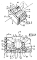
- Figure 1 attached shows a button cell receptacle as it is currently produced at present, and Figure 2 shows this same receptacle in place, with a button cell 7, in a base 5 of housing 3 for electronic telephone set.
- These lateral arms 15, 16 consequently have a certain flexibility in the direction of the axis 14, and they each carry, at their free end which arrives a short distance from the base 2, a lug 21, 22, which is directed in the opposite direction of the protuberance, respectively 11 and 12, carried by the same arm, 15 and 16 and cooperating with the base 2 to secure the receptacle 1 in the opening 4 of the base 5 of the housing 3.
- pins 21, 22 are considered to be located at the free "lower” part of the flexible arms 15, 16, their “upper” part has an inclined face 23, 24 roughly matching the outside diameter of the stack 7 in order to keep it in position in the direction of the axis 14.
- a keying device 25 is, of course, provided in cooperation with a corresponding notch 26 of the opening 4 in order to prevent the mounting of the receptacle 1 in the wrong meaning.
- This known receptacle has some drawbacks. To remove it, it is necessary to retract the lugs 21, 22 by exerting on the arms 15 and 16 a pressure in the direction indicated by the arrows F in FIG. 2. This can only be done by opening the housing 3 in order to have access to these wedging arms 15 and 16, so that the battery change cannot be carried out very quickly, as is generally desired. In addition, opening the telephone set presents a certain danger, because the components it contains are then exposed to electrostatic discharges. It is quite evident in FIG. 2 that it is not possible to extract the receptacle 1 without the risk of breaking the locking pins 21 and 22. Furthermore, if, as is the case in FIG.
- the opening 4 is very close to one of the vertical walls 29 of the housing 3, it is difficult to pass the finger through the small space e remaining between the arm 15 and this wall 29, so that the extraction of the receptacle 1 is difficult.
- the inclined holding faces 23 and 24 are quite difficult to separate from the stack 7, so that it is very difficult to extract it from its receptacle 1, once the latter has been removed from the housing 3.
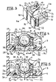
- FIGs 3 and 4 are respectively the counterparts of Figures 1 and 2, previously described, and similar or identical elements are there for clarity designated by the same reference numerals.
- the receptacle 1a shown in these Figures 3 and 4 is, like that, 1, according to Figures 1 and 2, made in one piece in a semi-plastic rigid. It has a central space 30 for receiving and wedging the stack 7 substantially identical to that of the receptacle 1, with a bottom plate 6, protrusions 11, 12, 13, and inclined retaining faces 23, 24. It also has two flexible arms 15, 16, located on either side of this central space 30, with, as previously, each a free end carrying a lug, respectively 21 and 22, capable of ensuring, in a removable manner and in cooperation with the base 2a of receptacle 1a, the wedging of this receptacle in the aforementioned opening 4 of base 5 of housing 3 of the telephone set.
- these second lugs 34, 35 are, when the receptacle 1a is in place in the opening 4, easily accessible from outside the housing 3 and, in order to facilitate this accessibility, the base 2a no longer reaches flush with the external face 28 of the base 5 of the housing 3, but it protrudes slightly towards the outside, by a height h of the order of a millimeter.
- the receptacle is put in place by clipping from the outside, that is to say without opening the housing 3 (see FIG. 4).
- the invention is not limited to the embodiment which has just been described, but it is, on the contrary, capable of being produced in equivalent forms, intended for example to receive other forms of batteries. Its good qualities of service and reliability allow it to be used in a wide variety of ways, and this receptacle can for example be inserted into a stiffener of cards, with memory or others, used in a field other than that of telephony.
Landscapes
- Chemical & Material Sciences (AREA)
- Chemical Kinetics & Catalysis (AREA)
- Electrochemistry (AREA)
- General Chemical & Material Sciences (AREA)
- Battery Mounting, Suspending (AREA)
- Apparatus Associated With Microorganisms And Enzymes (AREA)
- Electromechanical Clocks (AREA)
Priority Applications (1)
| Application Number | Priority Date | Filing Date | Title |
|---|---|---|---|
| AT90113153T ATE88596T1 (de) | 1989-07-12 | 1990-07-10 | Herausnehmbarer behaelter fuer batterien, insbesondere fuer knopfzellen. |
Applications Claiming Priority (2)
| Application Number | Priority Date | Filing Date | Title |
|---|---|---|---|
| FR8909398 | 1989-07-12 | ||
| FR8909398A FR2649681B1 (fr) | 1989-07-12 | 1989-07-12 | Receptacle amovible pour pile, en particulier pour pile-bouton |
Publications (2)
| Publication Number | Publication Date |
|---|---|
| EP0407966A1 EP0407966A1 (fr) | 1991-01-16 |
| EP0407966B1 true EP0407966B1 (fr) | 1993-04-21 |
Family
ID=9383728
Family Applications (1)
| Application Number | Title | Priority Date | Filing Date |
|---|---|---|---|
| EP90113153A Expired - Lifetime EP0407966B1 (fr) | 1989-07-12 | 1990-07-10 | Réceptacle amovible pour pile, en particulier pour pile-bouton |
Country Status (6)
| Country | Link |
|---|---|
| EP (1) | EP0407966B1 (da) |
| AT (1) | ATE88596T1 (da) |
| DE (1) | DE69001405T2 (da) |
| DK (1) | DK0407966T3 (da) |
| ES (1) | ES2040005T3 (da) |
| FR (1) | FR2649681B1 (da) |
Cited By (1)
| Publication number | Priority date | Publication date | Assignee | Title |
|---|---|---|---|---|
| WO2009111879A1 (en) * | 2008-03-10 | 2009-09-17 | Gang Chen | Battery housing |
Families Citing this family (2)
| Publication number | Priority date | Publication date | Assignee | Title |
|---|---|---|---|---|
| JP2973245B2 (ja) * | 1991-05-13 | 1999-11-08 | 松下電器産業株式会社 | 電子機器の電池収納装置 |
| US5586907A (en) * | 1995-08-25 | 1996-12-24 | The Whitaker Corporation | Battery connector |
Family Cites Families (4)
| Publication number | Priority date | Publication date | Assignee | Title |
|---|---|---|---|---|
| NL6607929A (da) * | 1966-06-08 | 1967-12-11 | ||
| US3537909A (en) * | 1968-01-11 | 1970-11-03 | Eastman Kodak Co | Battery holder |
| JPS6366847A (ja) * | 1986-09-09 | 1988-03-25 | Seiko Epson Corp | 電子機器の電源部構造 |
| JPH0747359B2 (ja) * | 1987-03-31 | 1995-05-24 | 三菱電機株式会社 | 半導体装置カ−ド |
-
1989
- 1989-07-12 FR FR8909398A patent/FR2649681B1/fr not_active Expired - Lifetime
-
1990
- 1990-07-10 DE DE9090113153T patent/DE69001405T2/de not_active Expired - Fee Related
- 1990-07-10 AT AT90113153T patent/ATE88596T1/de not_active IP Right Cessation
- 1990-07-10 EP EP90113153A patent/EP0407966B1/fr not_active Expired - Lifetime
- 1990-07-10 ES ES199090113153T patent/ES2040005T3/es not_active Expired - Lifetime
- 1990-07-10 DK DK90113153.2T patent/DK0407966T3/da active
Cited By (2)
| Publication number | Priority date | Publication date | Assignee | Title |
|---|---|---|---|---|
| WO2009111879A1 (en) * | 2008-03-10 | 2009-09-17 | Gang Chen | Battery housing |
| US8673481B2 (en) | 2008-03-10 | 2014-03-18 | Gang Chen | Battery system |
Also Published As
| Publication number | Publication date |
|---|---|
| ES2040005T3 (es) | 1993-10-01 |
| EP0407966A1 (fr) | 1991-01-16 |
| FR2649681B1 (fr) | 1991-09-20 |
| FR2649681A1 (fr) | 1991-01-18 |
| DE69001405T2 (de) | 1993-07-29 |
| ATE88596T1 (de) | 1993-05-15 |
| DK0407966T3 (da) | 1993-07-12 |
| DE69001405D1 (de) | 1993-05-27 |
Similar Documents
| Publication | Publication Date | Title |
|---|---|---|
| EP0515897B1 (fr) | Connecteur pour carte à circuits | |
| EP0637849B1 (fr) | Boîtier pour piles ou accumulateurs électriques | |
| CH635706A5 (fr) | Connecteur electrique pour un objet portatif. | |
| LU82241A1 (fr) | Recipients pour aliments | |
| CH656025A5 (fr) | Connecteur electrique. | |
| EP0403371A1 (fr) | Connecteur électrique pour le raccordement d'un câble multiconducteur blindé à un ensemble électrique placé à l'intérieur d'un châssis | |
| FR2805635A1 (fr) | Lecteur de carte et equipement mobile le comportant | |
| EP0674287A1 (fr) | Boîtier pour lecteur de carte à microcircuit | |
| FR2930849A3 (fr) | Prise electrique multiple de securite. | |
| EP1357650A1 (fr) | Dispositif de connexion d'un boítier électronique | |
| EP0145542B1 (fr) | Connecteur à force d'insertion nulle pour support rectangulaire de circuit, et pince de fermeture pour un tel connecteur | |
| EP3900967B1 (fr) | Dispositif de reception d'une batterie pour vehicule electrique et vehicule comportant un tel dispositif | |
| CH672662A5 (da) | ||
| EP3206260A1 (fr) | Appareil électrique ayant une borne de connexion à pression avec une agrafe de support guidant et limitant la déformation élastique du ressort de contact | |
| FR2545285A1 (fr) | Connecteur electrique a verrouillage perfectionne | |
| EP0847172B1 (fr) | Téléphone sans fil rechargeable dans toute position | |
| EP0407966B1 (fr) | Réceptacle amovible pour pile, en particulier pour pile-bouton | |
| FR3066328A1 (fr) | Ensemble de cable avec connecteur male a profil bas | |
| EP0136237B1 (fr) | Support de boîtier de circuit intégré | |
| FR2717625A1 (fr) | Boîtier pour lecteur de carte à microcircuit. | |
| WO2013144466A1 (fr) | Coque pour téléphone mobile et terminal mobile | |
| EP0654237B1 (fr) | Etui de présentation pour verre de lunettes | |
| FR2498380A1 (fr) | Connecteur pour equipement electrique en tiroir | |
| FR2914795A1 (fr) | Chargeur electrique en plusieurs pieces | |
| EP2312965B1 (fr) | Structure pour le transport et l'utilisation d'un equipement portable comprenant notamment des elements interconnectables par des liaisons filaires, tel qu'un equipement multimedia portable |
Legal Events
| Date | Code | Title | Description |
|---|---|---|---|
| PUAI | Public reference made under article 153(3) epc to a published international application that has entered the european phase |
Free format text: ORIGINAL CODE: 0009012 |
|
| AK | Designated contracting states |
Kind code of ref document: A1 Designated state(s): AT BE CH DE DK ES FR GB IT LI NL SE |
|
| 17P | Request for examination filed |
Effective date: 19910218 |
|
| 17Q | First examination report despatched |
Effective date: 19920602 |
|
| GRAA | (expected) grant |
Free format text: ORIGINAL CODE: 0009210 |
|
| AK | Designated contracting states |
Kind code of ref document: B1 Designated state(s): AT BE CH DE DK ES FR GB IT LI NL SE |
|
| REF | Corresponds to: |
Ref document number: 88596 Country of ref document: AT Date of ref document: 19930515 Kind code of ref document: T |
|
| GBT | Gb: translation of ep patent filed (gb section 77(6)(a)/1977) |
Effective date: 19930427 |
|
| REF | Corresponds to: |
Ref document number: 69001405 Country of ref document: DE Date of ref document: 19930527 |
|
| REG | Reference to a national code |
Ref country code: DK Ref legal event code: T3 |
|
| ITF | It: translation for a ep patent filed | ||
| REG | Reference to a national code |
Ref country code: ES Ref legal event code: FG2A Ref document number: 2040005 Country of ref document: ES Kind code of ref document: T3 |
|
| PLBE | No opposition filed within time limit |
Free format text: ORIGINAL CODE: 0009261 |
|
| STAA | Information on the status of an ep patent application or granted ep patent |
Free format text: STATUS: NO OPPOSITION FILED WITHIN TIME LIMIT |
|
| 26N | No opposition filed | ||
| EAL | Se: european patent in force in sweden |
Ref document number: 90113153.2 |
|
| PGFP | Annual fee paid to national office [announced via postgrant information from national office to epo] |
Ref country code: GB Payment date: 19980612 Year of fee payment: 9 |
|
| PGFP | Annual fee paid to national office [announced via postgrant information from national office to epo] |
Ref country code: SE Payment date: 19980624 Year of fee payment: 9 |
|
| PGFP | Annual fee paid to national office [announced via postgrant information from national office to epo] |
Ref country code: DK Payment date: 19980625 Year of fee payment: 9 Ref country code: AT Payment date: 19980625 Year of fee payment: 9 |
|
| PGFP | Annual fee paid to national office [announced via postgrant information from national office to epo] |
Ref country code: NL Payment date: 19980629 Year of fee payment: 9 Ref country code: FR Payment date: 19980629 Year of fee payment: 9 |
|
| PGFP | Annual fee paid to national office [announced via postgrant information from national office to epo] |
Ref country code: DE Payment date: 19980630 Year of fee payment: 9 |
|
| PGFP | Annual fee paid to national office [announced via postgrant information from national office to epo] |
Ref country code: CH Payment date: 19980701 Year of fee payment: 9 |
|
| PGFP | Annual fee paid to national office [announced via postgrant information from national office to epo] |
Ref country code: BE Payment date: 19980709 Year of fee payment: 9 |
|
| PGFP | Annual fee paid to national office [announced via postgrant information from national office to epo] |
Ref country code: ES Payment date: 19980716 Year of fee payment: 9 |
|
| PG25 | Lapsed in a contracting state [announced via postgrant information from national office to epo] |
Ref country code: GB Free format text: LAPSE BECAUSE OF NON-PAYMENT OF DUE FEES Effective date: 19990710 Ref country code: AT Free format text: LAPSE BECAUSE OF NON-PAYMENT OF DUE FEES Effective date: 19990710 |
|
| PG25 | Lapsed in a contracting state [announced via postgrant information from national office to epo] |
Ref country code: ES Free format text: LAPSE BECAUSE OF NON-PAYMENT OF DUE FEES Effective date: 19990711 |
|
| PG25 | Lapsed in a contracting state [announced via postgrant information from national office to epo] |
Ref country code: SE Free format text: THE PATENT HAS BEEN ANNULLED BY A DECISION OF A NATIONAL AUTHORITY Effective date: 19990730 |
|
| PG25 | Lapsed in a contracting state [announced via postgrant information from national office to epo] |
Ref country code: LI Free format text: LAPSE BECAUSE OF NON-PAYMENT OF DUE FEES Effective date: 19990731 Ref country code: FR Free format text: THE PATENT HAS BEEN ANNULLED BY A DECISION OF A NATIONAL AUTHORITY Effective date: 19990731 Ref country code: CH Free format text: LAPSE BECAUSE OF NON-PAYMENT OF DUE FEES Effective date: 19990731 Ref country code: BE Free format text: LAPSE BECAUSE OF NON-PAYMENT OF DUE FEES Effective date: 19990731 |
|
| PG25 | Lapsed in a contracting state [announced via postgrant information from national office to epo] |
Ref country code: DK Free format text: LAPSE BECAUSE OF NON-PAYMENT OF DUE FEES Effective date: 19990802 |
|
| BERE | Be: lapsed |
Owner name: ALCATEL BUSINESS SYSTEMS Effective date: 19990731 |
|
| PG25 | Lapsed in a contracting state [announced via postgrant information from national office to epo] |
Ref country code: NL Free format text: LAPSE BECAUSE OF NON-PAYMENT OF DUE FEES Effective date: 20000201 |
|
| GBPC | Gb: european patent ceased through non-payment of renewal fee |
Effective date: 19990710 |
|
| REG | Reference to a national code |
Ref country code: CH Ref legal event code: PL |
|
| REG | Reference to a national code |
Ref country code: DK Ref legal event code: EBP |
|
| EUG | Se: european patent has lapsed |
Ref document number: 90113153.2 |
|
| NLV4 | Nl: lapsed or anulled due to non-payment of the annual fee |
Effective date: 20000201 |
|
| PG25 | Lapsed in a contracting state [announced via postgrant information from national office to epo] |
Ref country code: DE Free format text: LAPSE BECAUSE OF NON-PAYMENT OF DUE FEES Effective date: 20000503 |
|
| REG | Reference to a national code |
Ref country code: FR Ref legal event code: ST |
|
| REG | Reference to a national code |
Ref country code: ES Ref legal event code: FD2A Effective date: 20000810 |
|
| PG25 | Lapsed in a contracting state [announced via postgrant information from national office to epo] |
Ref country code: IT Free format text: LAPSE BECAUSE OF NON-PAYMENT OF DUE FEES;WARNING: LAPSES OF ITALIAN PATENTS WITH EFFECTIVE DATE BEFORE 2007 MAY HAVE OCCURRED AT ANY TIME BEFORE 2007. THE CORRECT EFFECTIVE DATE MAY BE DIFFERENT FROM THE ONE RECORDED. Effective date: 20050710 |