EP0407199B1 - Image forming apparatus - Google Patents
Image forming apparatus Download PDFInfo
- Publication number
- EP0407199B1 EP0407199B1 EP19900307372 EP90307372A EP0407199B1 EP 0407199 B1 EP0407199 B1 EP 0407199B1 EP 19900307372 EP19900307372 EP 19900307372 EP 90307372 A EP90307372 A EP 90307372A EP 0407199 B1 EP0407199 B1 EP 0407199B1
- Authority
- EP
- European Patent Office
- Prior art keywords
- scanning means
- reflector
- scanner assembly
- scanning
- optical scanner
- Prior art date
- Legal status (The legal status is an assumption and is not a legal conclusion. Google has not performed a legal analysis and makes no representation as to the accuracy of the status listed.)
- Expired - Lifetime
Links
- 230000003287 optical effect Effects 0.000 claims description 27
- 230000005855 radiation Effects 0.000 claims description 20
- 210000001747 pupil Anatomy 0.000 claims description 12
- 230000000712 assembly Effects 0.000 claims description 8
- 238000000429 assembly Methods 0.000 claims description 8
- 238000001931 thermography Methods 0.000 claims description 6
- 229910052732 germanium Inorganic materials 0.000 description 5
- GNPVGFCGXDBREM-UHFFFAOYSA-N germanium atom Chemical compound [Ge] GNPVGFCGXDBREM-UHFFFAOYSA-N 0.000 description 5
- 239000011521 glass Substances 0.000 description 4
- 210000000887 face Anatomy 0.000 description 3
- 241000234479 Narcissus Species 0.000 description 2
- 230000000694 effects Effects 0.000 description 2
- 230000035945 sensitivity Effects 0.000 description 2
- 230000004075 alteration Effects 0.000 description 1
- 238000009432 framing Methods 0.000 description 1
- 238000003384 imaging method Methods 0.000 description 1
- 238000010348 incorporation Methods 0.000 description 1
- 239000011159 matrix material Substances 0.000 description 1
- 238000012986 modification Methods 0.000 description 1
- 230000004048 modification Effects 0.000 description 1
- 230000010355 oscillation Effects 0.000 description 1
Images

Classifications
-
- G—PHYSICS
- G02—OPTICS
- G02B—OPTICAL ELEMENTS, SYSTEMS OR APPARATUS
- G02B26/00—Optical devices or arrangements for the control of light using movable or deformable optical elements
- G02B26/08—Optical devices or arrangements for the control of light using movable or deformable optical elements for controlling the direction of light
- G02B26/10—Scanning systems
- G02B26/12—Scanning systems using multifaceted mirrors
- G02B26/129—Systems in which the scanning light beam is repeatedly reflected from the polygonal mirror
-
- H—ELECTRICITY
- H04—ELECTRIC COMMUNICATION TECHNIQUE
- H04N—PICTORIAL COMMUNICATION, e.g. TELEVISION
- H04N3/00—Scanning details of television systems; Combination thereof with generation of supply voltages
- H04N3/02—Scanning details of television systems; Combination thereof with generation of supply voltages by optical-mechanical means only
- H04N3/08—Scanning details of television systems; Combination thereof with generation of supply voltages by optical-mechanical means only having a moving reflector
- H04N3/09—Scanning details of television systems; Combination thereof with generation of supply voltages by optical-mechanical means only having a moving reflector for electromagnetic radiation in the invisible region, e.g. infrared
Definitions
- the present invention relates to image forming apparatus and, in particular, but not exclusively to image forming apparatus for forming a visible image representing the differential thermal radiance of a scene.
- thermal imagers Many forms of apparatus for forming an image representing the differential thermal radiance of a scene are known, and are frequently referred to as thermal imagers.
- thermal imagers In view of the technical difficulties of fabricating a large matrix of infra-red (IR) sensitive detectors, it is usual to scan the scene to be viewed in both line and frame directions with an array of detectors, a number of detectors being used so as to increase sensitivity.
- a relatively large scanning aperture is used, which may typically be 10 millimetres, with scanning occurring, typically, through 45° in one scan direction and 30° in the other.
- Direct view image reproduction systems have, therefore, been proposed, which have improved reliability and lower power consumption.
- a scanning array of light emitting diodes LEDs
- the scene being reconstructed by scanning the array of LEDs across the viewing aperture in a like manner to the scanning IR detectors used to image the scene.
- IR scanners It is highly desirable to incorporate such IR scanners into telescopes so as to provide long range images of acceptable quality.
- the scanners should, however, be introduced into the telescope using the minimum of additional optical components so as to minimise both propagation losses and the weight of the device.
- GB Patent GB-A-1587098 discloses such a system in which a polygonal reflector is rotated at high speed so as to line scan an array of IR detectors.
- the IR radiation is reflected from reflective faces of the rotating polygonal reflector onto a reflector of a frame scanner.
- the frame scanner consists of a pair of reflectors disposed diametrically about the rotating reflector which are oscillated at a frame scan frequency, typically 50 Hz, in a direction perpendicular to the line scan direction.
- a frame scan frequency typically 50 Hz
- US-A-4202597 discloses a system with features comparable to those in the preamble to claim 1.
- US-A-4029389 discloses a radiation scanning system of this general type.
- the present invention seeks to alleviate the problems associated with such direct view thermal imagers by the provision of an assembly having high quality, compared to existing devices, object and pupil imagery, compact size and low weight coupled with minimal distortion in both the infra-red and visible channels.
- an optical scanner assembly comprising first scanning means including first and further reflectors for scanning a scene respectively about first and second axes, second scanning means including first and further reflectors for scanning emitted radiation about first and second axes for providing a visible representation of the scene, the first scanning means including an intermediate optical assembly for defining an image pupil on the further reflector thereof, and the second scanning means including an intermediate optical assembly for defining a path for the emitted radiation between the first and further reflectors of the second scanning means, characterised in that the intermediate optical assemblies of the first and the second scanning means are arranged substantially concentric with respect to the image pupil defined on the further reflector of the first scanning means.
- the intermediate optical assemblies of the first and second scanning means may comprise a concave and convex reflectors and a concentric lens.
- the first reflector of the first scanning means and the further reflector of the second scanning means may comprise reflective surfaces of a prism.
- the further reflector of the first scanning means and the first reflector of the second scanning means may comprise the opposite sides of a substantially planar support.
- the concentric lenses of the first and second scanning means may comprise on one surface thereof a strip reflector.
- the scanner assembly may include an infra red telescope eyepiece.
- the scanner assembly may also comprise a visible lightperiscope eyepiece.
- the present invention may also comprise a thermal imaging device comprising a scanner as described above and including an array of infra red detectors for scanning the scene by way of the first scanning means and an array of light emitting diodes for providing the emitted radiation scanned by the second scanning means.
- a thermal imaging device comprising a scanner as described above and including an array of infra red detectors for scanning the scene by way of the first scanning means and an array of light emitting diodes for providing the emitted radiation scanned by the second scanning means.
- an optical scanner 2 comprises first and second scanner assemblies 4, 6.
- the first scanning assembly 4 includes a first reflector 8, for receiving infra-red radiation 10 from a scene via a telescope objective 12.
- the first reflector 8 reflects the impinging radiation 10 via an intermediate optical assembly consisting of a concave reflector 14, strip reflector 16, and concentric germanium lens 18, to a further reflector 20, where it is directed via a lens assembly 22 to an array of infra-red detectors 24, as shown in Figure 2.
- the signals produced by the detectors 24 are supplied via respective signal processing channels 26 to light emissive diodes (LEDs) 28.
- LEDs light emissive diodes
- the second scanner assembly 6 comprises a first reflector 30 for receiving the visible radiation emitted by the LEDs 28 via a lens assembly 32, the reflector 30 of the second scanner 6 and the reflector 20 of the first scanner 4 being formed on opposite sides of a planar sheet or support 34.
- the scanner assembly 6 also includes an intermediate optical assembly consisting of a concentric glass lens 36 and concave reflector 38, the glass lens 36 having a strip reflector 40 disposed on the surface thereof facing the reflector 38 in a like manner to the germanium lens 18.
- a further reflector 42 is provided for directing the visible radiation from the LEDs 28 to an eyepiece 44 of a visible light periscope.
- the reflectors 8 and 42 are, preferably, reflective faces of a prism (not shown) which is caused to oscillate at approximately 250Hz, by any suitable drive means, about an axis 46, hereinafter referred to as the line scan axis, as shown by the arrow 48 in Figure 1.
- the support 34, carrying the reflectors 20, 30 is mounted for oscillation about an axis 50, as shown in Figure 2, hereinafter referred to as the frame scan axis.
- the thermal or infra red radiance 10 from a scene to be viewed passes through the telescope eyepiece 12 onto the reflector 8.
- the detector 8, oscillating about the line scan axis 46 causes the IR radiation to scan in the xy plane shown in Figure 1 so as to scan across the surface of concave reflector 14.
- the IR radiation is reflected onto the strip mirror 16 formed on the surface of the germanium lens 18, back to the reflector 14 and then through lens 18 to form an image pupil on the reflector 20, which is oscillating at a frequency of about 50Hz about the frame scan axis 50 so as to cause the beam to scan in the yz plane shown in Figure 1.
- the array of IR detectors 24 is caused to line and frame scan the scene being viewed.
- the signals produced by IR detectors 24 are passed by the signal processing channels 26 to the array of LEDs 28.
- the visible radiation emitted by LEDs 28 is reflected by reflector 30, through the glass lens 36 onto reflector 38.
- the visible radiation is caused to scan across the reflector 38.
- the visible radiation is then reflected by strip reflector 40 and again by concave reflector 38 to impinge on reflector 42.
- Reflector 42 which is fixed relative to the reflector 8, is also oscillating about the line scan axis 46 and hence, the visible radiation emitted by the LEDs 28 is caused to scan in line and frame to provide a viewable image of the scene in the eyepiece 44 of the visible light periscope.
- any reflections from the principal ray such as those generated at the surfaces of the lenses 18 and 36, are reflected back down the principal ray, thereby avoiding the "Narcissus Effect".
- the term "Narcissus effect” will be assumed to be readily understood by persons skilled in this art and hence, will not be discribed in the present application.
- pupils of 10 millimetres diameter can be scanned over angles of 90° by 60°, compared to scanning angle limits of approximately 60° by 45° with known scanners. Furthermore, as the line and frame scan axes can be accurately maintained, pupil wander, a problem in the known scanners incorporating a rotating polygon, is virtually eliminated.
- This high quality pupil imagery provides an optical scanner with minimal distortion in both the visible and infra red channels which is compact size, and of relatively low weight. Additionally, radiation propogation losses are low.
- the reflectors 8 and 42 can be formed other than on the surfaces of a prism and reflectors 20 and 30 need not necessarily be formed on the opposite sides of a common support member 34.
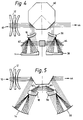
- Such an example is shown in figure 3, where the wedge mirror pair 8 and 42 have been replaced by a polygon mirror 60, to permit very high speed scanning.
- fold mirrors 62 and 64 have been incorporated to reflect the radiation as desired for effective operation.
- FIGS 4 and 5 show further alternative configurations of scanner assemblies embodying the main features of the present invention.
Description
- The present invention relates to image forming apparatus and, in particular, but not exclusively to image forming apparatus for forming a visible image representing the differential thermal radiance of a scene.
- Many forms of apparatus for forming an image representing the differential thermal radiance of a scene are known, and are frequently referred to as thermal imagers. In view of the technical difficulties of fabricating a large matrix of infra-red (IR) sensitive detectors, it is usual to scan the scene to be viewed in both line and frame directions with an array of detectors, a number of detectors being used so as to increase sensitivity. Furthermore, to enhance sensitivity a relatively large scanning aperture is used, which may typically be 10 millimetres, with scanning occurring, typically, through 45° in one scan direction and 30° in the other.
- There is also a need to find a convenient means to construct a viewable image formed by the detector. Electronic scan converters in combination with conventional cathode ray tubes have been proposed for this purpose but the systems are rather complex and have a relatively high power consumption.
- Direct view image reproduction systems have, therefore, been proposed, which have improved reliability and lower power consumption. In direct view imagers a scanning array of light emitting diodes (LEDs) is usually employed, the scene being reconstructed by scanning the array of LEDs across the viewing aperture in a like manner to the scanning IR detectors used to image the scene. It is highly desirable to incorporate such IR scanners into telescopes so as to provide long range images of acceptable quality. The scanners should, however, be introduced into the telescope using the minimum of additional optical components so as to minimise both propagation losses and the weight of the device.
- Scanning assemblies for IR detectors for incorporation into telescopes are known, GB Patent GB-A-1587098 discloses such a system in which a polygonal reflector is rotated at high speed so as to line scan an array of IR detectors. The IR radiation is reflected from reflective faces of the rotating polygonal reflector onto a reflector of a frame scanner. The frame scanner consists of a pair of reflectors disposed diametrically about the rotating reflector which are oscillated at a frame scan frequency, typically 50 Hz, in a direction perpendicular to the line scan direction. However, in such arrangements the rocking motion of the framing mirrors cause wander of the image pupil formed on the reflective faces of the rotating line scanner.
- US-A-4202597 discloses a system with features comparable to those in the preamble to claim 1. US-A-4029389 discloses a radiation scanning system of this general type.
- The present invention seeks to alleviate the problems associated with such direct view thermal imagers by the provision of an assembly having high quality, compared to existing devices, object and pupil imagery, compact size and low weight coupled with minimal distortion in both the infra-red and visible channels.
- Accordingly, there is provided an optical scanner assembly comprising first scanning means including first and further reflectors for scanning a scene respectively about first and second axes, second scanning means including first and further reflectors for scanning emitted radiation about first and second axes for providing a visible representation of the scene, the first scanning means including an intermediate optical assembly for defining an image pupil on the further reflector thereof, and the second scanning means including an intermediate optical assembly for defining a path for the emitted radiation between the first and further reflectors of the second scanning means, characterised in that the intermediate optical assemblies of the first and the second scanning means are arranged substantially concentric with respect to the image pupil defined on the further reflector of the first scanning means.
- The intermediate optical assemblies of the first and second scanning means may comprise a concave and convex reflectors and a concentric lens.
- The first reflector of the first scanning means and the further reflector of the second scanning means may comprise reflective surfaces of a prism.
- The further reflector of the first scanning means and the first reflector of the second scanning means may comprise the opposite sides of a substantially planar support.
- The concentric lenses of the first and second scanning means may comprise on one surface thereof a strip reflector.
- The use of a strip reflector and a germanium lens in the intermediate optical assembly to give extra folding is found advantageous.
- Alternatively, the scanner assembly may include an infra red telescope eyepiece.
- The scanner assembly may also comprise a visible lightperiscope eyepiece.
- The present invention may also comprise a thermal imaging device comprising a scanner as described above and including an array of infra red detectors for scanning the scene by way of the first scanning means and an array of light emitting diodes for providing the emitted radiation scanned by the second scanning means.
- The present invention will now be described, by way of example only, with respect to the accompanying drawings in which like features are represented by like numerals and:
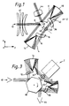
- Figure 1 is a schematic plan view of a scanner assembly according to the invention;
- Figure 2 is a schematic side view of a thermal imager incoporating the assembly illustrated in figure 1; and
- Figures 3, 4 and 5 are plan views of alternative scanner assemblies according to the invention.
- Referring to the drawings, an
optical scanner 2 comprises first and second scanner assemblies 4, 6. The first scanning assembly 4 includes afirst reflector 8, for receiving infra-red radiation 10 from a scene via atelescope objective 12. Thefirst reflector 8 reflects the impingingradiation 10 via an intermediate optical assembly consisting of aconcave reflector 14,strip reflector 16, andconcentric germanium lens 18, to afurther reflector 20, where it is directed via alens assembly 22 to an array of infra-red detectors 24, as shown in Figure 2. The signals produced by thedetectors 24 are supplied via respectivesignal processing channels 26 to light emissive diodes (LEDs) 28. - The second scanner assembly 6 comprises a
first reflector 30 for receiving the visible radiation emitted by theLEDs 28 via alens assembly 32, thereflector 30 of the second scanner 6 and thereflector 20 of the first scanner 4 being formed on opposite sides of a planar sheet or support 34. The scanner assembly 6 also includes an intermediate optical assembly consisting of aconcentric glass lens 36 andconcave reflector 38, theglass lens 36 having astrip reflector 40 disposed on the surface thereof facing thereflector 38 in a like manner to thegermanium lens 18. Afurther reflector 42 is provided for directing the visible radiation from theLEDs 28 to aneyepiece 44 of a visible light periscope. - The
reflectors axis 46, hereinafter referred to as the line scan axis, as shown by thearrow 48 in Figure 1. Thesupport 34, carrying thereflectors axis 50, as shown in Figure 2, hereinafter referred to as the frame scan axis. - In operation, the thermal or infra
red radiance 10 from a scene to be viewed passes through thetelescope eyepiece 12 onto thereflector 8. Thedetector 8, oscillating about theline scan axis 46 causes the IR radiation to scan in the xy plane shown in Figure 1 so as to scan across the surface ofconcave reflector 14. The IR radiation is reflected onto thestrip mirror 16 formed on the surface of thegermanium lens 18, back to thereflector 14 and then throughlens 18 to form an image pupil on thereflector 20, which is oscillating at a frequency of about 50Hz about theframe scan axis 50 so as to cause the beam to scan in the yz plane shown in Figure 1. In this manner, the array ofIR detectors 24 is caused to line and frame scan the scene being viewed. The signals produced byIR detectors 24 are passed by thesignal processing channels 26 to the array ofLEDs 28. The visible radiation emitted byLEDs 28 is reflected byreflector 30, through theglass lens 36 ontoreflector 38. As thereflector 30 is oscillating about the frame scan axis the visible radiation is caused to scan across thereflector 38. The visible radiation is then reflected bystrip reflector 40 and again byconcave reflector 38 to impinge onreflector 42. -
Reflector 42, which is fixed relative to thereflector 8, is also oscillating about theline scan axis 46 and hence, the visible radiation emitted by theLEDs 28 is caused to scan in line and frame to provide a viewable image of the scene in theeyepiece 44 of the visible light periscope. - It will be realised from the foregoing description that all optical surfaces of the
reflectors lenses reflector 20. The radii of curvature and the thicknesses of the germanium lens and glass lens are selected to minimise the image and pupil aberrations of thespherical mirrors lenses - With the
scanner assembly 2 of the present invention pupils of 10 millimetres diameter can be scanned over angles of 90° by 60°, compared to scanning angle limits of approximately 60° by 45° with known scanners. Furthermore, as the line and frame scan axes can be accurately maintained, pupil wander, a problem in the known scanners incorporating a rotating polygon, is virtually eliminated. This high quality pupil imagery provides an optical scanner with minimal distortion in both the visible and infra red channels which is compact size, and of relatively low weight. Additionally, radiation propogation losses are low. - Although the present invention has been described with respect to a particular embodiment, it should be realised that modifications can be effected whilst remaining within the scope of the invention. For example, the
reflectors reflectors common support member 34. Such an example is shown in figure 3, where thewedge mirror pair polygon mirror 60, to permit very high speed scanning. - In
addition fold mirrors - Figures 4 and 5 show further alternative configurations of scanner assemblies embodying the main features of the present invention.
Claims (10)
- An optical scanner assembly comprising first scanning means (4) including a first and a further reflector for scanning a scene respectively about first and second axes, second scanning means (6) including a first and a further reflector for scanning emitted radiation about first and second axes for providing a visible representation of the scene, the first scanning means (4) including an intermediate optical assembly (14) for defining an image pupil on the further reflector (20) thereof, and the second scanning means including an intermediate optical assembly for defining a path for the emitted radiation between the first (30) and further (42) reflectors of the second scanning means, characterised in that the intermediate optical assemblies of the first and second scanning means are arranged substantially concentric with respect to the image pupil defined on the further reflector of the first scanning means.
- An optical scanner assembly according to claim 1 wherein the intermediate optical assemblies of the first and second scanning means comprise concave and convex reflectors and a concentric lens.
- An optical scanner assembly according to claims 1 or 2 wherein the first reflector of the first scanning means and the further reflector of the second scanning means comprise reflective surfaces of a prism.
- An optical scanner assembly according to claims 1 to 3 wherein the further reflector of the first scanning means and the first reflector of the second scanning means may comprise the opposite sides of a substantially planar support (34).
- An optical scanner assembly according to claims 1 to 4 wherein the concentric lenses of the first and second scanning means comprise on one surface thereof a strip reflector (16,40).
- An optical scanner assembly according to any of claims 1 to 5 wherein the scanner assembly includes an infra red telescope objective.
- An optical scanner assembly according to any of claims 1 to 5 wherein the scanner assembly comprises a visible light periscope eyepiece.
- A thermal imaging device including an optical scanner assembly as described by any of the above claims.
- A thermal imaging device according to claim 8 wherein the thermal imaging device includes an array of infra red detectors (24) for scanning the scene by way of the first scanning means.
- A thermal imaging device according to claim 8 wherein the thermal imaging device includes an array of light emitting diodes (28) for providing the emitted radiation scanned by the second scanning means.
Applications Claiming Priority (2)
| Application Number | Priority Date | Filing Date | Title |
|---|---|---|---|
| GB8915612 | 1989-07-07 | ||
| GB898915612A GB8915612D0 (en) | 1989-07-07 | 1989-07-07 | Improvements in or relating to image forming apparatus |
Publications (3)
| Publication Number | Publication Date |
|---|---|
| EP0407199A2 EP0407199A2 (en) | 1991-01-09 |
| EP0407199A3 EP0407199A3 (en) | 1991-10-09 |
| EP0407199B1 true EP0407199B1 (en) | 1996-03-06 |
Family
ID=10659695
Family Applications (1)
| Application Number | Title | Priority Date | Filing Date |
|---|---|---|---|
| EP19900307372 Expired - Lifetime EP0407199B1 (en) | 1989-07-07 | 1990-07-05 | Image forming apparatus |
Country Status (3)
| Country | Link |
|---|---|
| EP (1) | EP0407199B1 (en) |
| DE (1) | DE69025660T2 (en) |
| GB (1) | GB8915612D0 (en) |
Families Citing this family (1)
| Publication number | Priority date | Publication date | Assignee | Title |
|---|---|---|---|---|
| US5353055A (en) * | 1991-04-16 | 1994-10-04 | Nec Corporation | Image pickup system with an image pickup device for control |
Family Cites Families (6)
| Publication number | Priority date | Publication date | Assignee | Title |
|---|---|---|---|---|
| US3287559A (en) * | 1963-10-04 | 1966-11-22 | Barnes Eng Co | Infrared thermogram camera and scanning means therefor |
| US3728545A (en) * | 1971-04-28 | 1973-04-17 | Honeywell Inc | Infrared imaging apparatus |
| US4029389A (en) * | 1975-07-26 | 1977-06-14 | Barr And Stroud Limited | Radiation scanning system |
| GB1567320A (en) * | 1977-01-07 | 1980-05-14 | Rank Organisation Ltd | Scanners |
| GB1587098A (en) * | 1978-05-25 | 1981-04-01 | Emi Ltd | Image forming apparatus |
| US4340888A (en) * | 1980-04-01 | 1982-07-20 | Martin Marietta Corporation | Scan linerization method and device |
-
1989
- 1989-07-07 GB GB898915612A patent/GB8915612D0/en active Pending
-
1990
- 1990-07-05 DE DE1990625660 patent/DE69025660T2/en not_active Expired - Fee Related
- 1990-07-05 EP EP19900307372 patent/EP0407199B1/en not_active Expired - Lifetime
Also Published As
| Publication number | Publication date |
|---|---|
| GB8915612D0 (en) | 1990-05-30 |
| EP0407199A2 (en) | 1991-01-09 |
| DE69025660D1 (en) | 1996-04-11 |
| EP0407199A3 (en) | 1991-10-09 |
| DE69025660T2 (en) | 1996-10-24 |
Similar Documents
| Publication | Publication Date | Title |
|---|---|---|
| US4538181A (en) | Optical scanner | |
| US5049740A (en) | Multiple field of view sensor | |
| JP3967784B2 (en) | Optics assembly for observing panoramic scenes | |
| EP0050970B1 (en) | Opto-mechanical scanning mechanism | |
| JPH11331654A (en) | Omnidirectional viewing angle sensor | |
| CA2342612A1 (en) | Scanning apparatus | |
| JPH05241108A (en) | Thermal video system | |
| EP0207153B1 (en) | Multiple field of view sensor | |
| US3614194A (en) | Wide field optical scanner | |
| US4017732A (en) | Radiation scanning system | |
| US3949225A (en) | Infrared imaging apparatus | |
| GB1586099A (en) | Radiation scanning system | |
| EP0123038B1 (en) | Optical scanner | |
| US3956586A (en) | Method of optical scanning | |
| US4687933A (en) | Optical and mechanical scanning device | |
| US6252565B1 (en) | Elliptical cavity optical retinal display | |
| US4912321A (en) | Radiation scanning system with pupil control | |
| EP0407199B1 (en) | Image forming apparatus | |
| EP0051894B1 (en) | Imaging apparatus | |
| US4106845A (en) | Infra-red scanner | |
| CA1119029A (en) | Method of and means for scanning images | |
| GB2179758A (en) | An optico-mechanical scanning device | |
| US5650869A (en) | Point relay scanner utilizing ellipsoidal mirrors | |
| US5136417A (en) | Optical system | |
| JP3425583B2 (en) | Optical device |
Legal Events
| Date | Code | Title | Description |
|---|---|---|---|
| PUAI | Public reference made under article 153(3) epc to a published international application that has entered the european phase |
Free format text: ORIGINAL CODE: 0009012 |
|
| AK | Designated contracting states |
Kind code of ref document: A2 Designated state(s): DE FR GB |
|
| PUAL | Search report despatched |
Free format text: ORIGINAL CODE: 0009013 |
|
| AK | Designated contracting states |
Kind code of ref document: A3 Designated state(s): DE FR GB |
|
| 17P | Request for examination filed |
Effective date: 19920320 |
|
| 17Q | First examination report despatched |
Effective date: 19940610 |
|
| RAP1 | Party data changed (applicant data changed or rights of an application transferred) |
Owner name: PILKINGTON THORN OPTRONICS LIMITED |
|
| GRAA | (expected) grant |
Free format text: ORIGINAL CODE: 0009210 |
|
| AK | Designated contracting states |
Kind code of ref document: B1 Designated state(s): DE FR GB |
|
| REF | Corresponds to: |
Ref document number: 69025660 Country of ref document: DE Date of ref document: 19960411 |
|
| ET | Fr: translation filed | ||
| PLBE | No opposition filed within time limit |
Free format text: ORIGINAL CODE: 0009261 |
|
| STAA | Information on the status of an ep patent application or granted ep patent |
Free format text: STATUS: NO OPPOSITION FILED WITHIN TIME LIMIT |
|
| 26N | No opposition filed | ||
| PGFP | Annual fee paid to national office [announced via postgrant information from national office to epo] |
Ref country code: GB Payment date: 19980630 Year of fee payment: 9 |
|
| PGFP | Annual fee paid to national office [announced via postgrant information from national office to epo] |
Ref country code: FR Payment date: 19980709 Year of fee payment: 9 |
|
| PGFP | Annual fee paid to national office [announced via postgrant information from national office to epo] |
Ref country code: DE Payment date: 19980713 Year of fee payment: 9 |
|
| PG25 | Lapsed in a contracting state [announced via postgrant information from national office to epo] |
Ref country code: GB Free format text: LAPSE BECAUSE OF NON-PAYMENT OF DUE FEES Effective date: 19990705 |
|
| PG25 | Lapsed in a contracting state [announced via postgrant information from national office to epo] |
Ref country code: FR Free format text: THE PATENT HAS BEEN ANNULLED BY A DECISION OF A NATIONAL AUTHORITY Effective date: 19990731 |
|
| GBPC | Gb: european patent ceased through non-payment of renewal fee |
Effective date: 19990705 |
|
| PG25 | Lapsed in a contracting state [announced via postgrant information from national office to epo] |
Ref country code: DE Free format text: LAPSE BECAUSE OF NON-PAYMENT OF DUE FEES Effective date: 20000503 |
|
| REG | Reference to a national code |
Ref country code: FR Ref legal event code: ST |