EP0407018A1 - Collapsible container apparatus for use in the storage and transportation of fluid material - Google Patents
Collapsible container apparatus for use in the storage and transportation of fluid material Download PDFInfo
- Publication number
- EP0407018A1 EP0407018A1 EP90305304A EP90305304A EP0407018A1 EP 0407018 A1 EP0407018 A1 EP 0407018A1 EP 90305304 A EP90305304 A EP 90305304A EP 90305304 A EP90305304 A EP 90305304A EP 0407018 A1 EP0407018 A1 EP 0407018A1
- Authority
- EP
- European Patent Office
- Prior art keywords
- container apparatus
- collapsible container
- outer bag
- fluid material
- discharge means
- Prior art date
- Legal status (The legal status is an assumption and is not a legal conclusion. Google has not performed a legal analysis and makes no representation as to the accuracy of the status listed.)
- Granted
Links
Images


Classifications
-
- B—PERFORMING OPERATIONS; TRANSPORTING
- B65—CONVEYING; PACKING; STORING; HANDLING THIN OR FILAMENTARY MATERIAL
- B65D—CONTAINERS FOR STORAGE OR TRANSPORT OF ARTICLES OR MATERIALS, e.g. BAGS, BARRELS, BOTTLES, BOXES, CANS, CARTONS, CRATES, DRUMS, JARS, TANKS, HOPPERS, FORWARDING CONTAINERS; ACCESSORIES, CLOSURES, OR FITTINGS THEREFOR; PACKAGING ELEMENTS; PACKAGES
- B65D88/00—Large containers
- B65D88/16—Large containers flexible
- B65D88/20—Large containers flexible with rigid end-walls
-
- B—PERFORMING OPERATIONS; TRANSPORTING
- B65—CONVEYING; PACKING; STORING; HANDLING THIN OR FILAMENTARY MATERIAL
- B65D—CONTAINERS FOR STORAGE OR TRANSPORT OF ARTICLES OR MATERIALS, e.g. BAGS, BARRELS, BOTTLES, BOXES, CANS, CARTONS, CRATES, DRUMS, JARS, TANKS, HOPPERS, FORWARDING CONTAINERS; ACCESSORIES, CLOSURES, OR FITTINGS THEREFOR; PACKAGING ELEMENTS; PACKAGES
- B65D88/00—Large containers
- B65D88/16—Large containers flexible
- B65D88/18—Large containers flexible bellows-shaped
-
- B—PERFORMING OPERATIONS; TRANSPORTING
- B65—CONVEYING; PACKING; STORING; HANDLING THIN OR FILAMENTARY MATERIAL
- B65D—CONTAINERS FOR STORAGE OR TRANSPORT OF ARTICLES OR MATERIALS, e.g. BAGS, BARRELS, BOTTLES, BOXES, CANS, CARTONS, CRATES, DRUMS, JARS, TANKS, HOPPERS, FORWARDING CONTAINERS; ACCESSORIES, CLOSURES, OR FITTINGS THEREFOR; PACKAGING ELEMENTS; PACKAGES
- B65D88/00—Large containers
- B65D88/54—Large containers characterised by means facilitating filling or emptying
- B65D88/58—Large containers characterised by means facilitating filling or emptying by displacement of walls
- B65D88/60—Large containers characterised by means facilitating filling or emptying by displacement of walls of internal walls
- B65D88/62—Large containers characterised by means facilitating filling or emptying by displacement of walls of internal walls the walls being deformable
Definitions
- This invention relates to collapsible container apparatus for the storage and transportation of fluid material such for example as liquids, powders and granular materials
- collapsible container apparatus for the storage and transportation of fluid material is known, for example from our UK Patent No. 2189773.
- the collapsible container apparatus may be such that it is not possible for end users of the container apparatus easily to obtain the last small amount of fluid material in the collapsible container apparatus, due to the fact that the fluid material is usually discharged at a point slightly above the bottom of the collapsible container apparatus. It is an aim of the present invention to obviate or reduce the above mentioned problem.
- this invention provides collapsible container apparatus for the storage and transportation of fluid material, which collapsible container apparatus comprises an outer bag which has a bottom and sides and which is made from a flexible material so that the outer bag is collapsible, a rigid top portion which is attached to the sides of the outer bag, a rigid base, horizontally extending constraint members which are for constraining the sides of the outer bag when the collapsible container apparatus is in use and contains the fluid material, and elongate support members which are positioned adjacent the sides of the outer bag, the elongate support members being such that they are movable from a first position in which they extend between the rigid top portion and the rigid base to hold the rigid top portion firm with respect to the rigid base, to a second position in which they allow the sides of the outer bag to collapse by folding between the constraint members, the outer bag being such that it is not attached to the rigid base, the outer bag having discharge means which is located above the bottom of the outer bag, and the collapsible container apparatus further including auxiliary
- auxiliary discharge means thus provides a convenient way of obtaining the last amount of fluid material that may be remaining in the collapsible container apparatus.
- the rigid top portion may be sealed when the collapsible container apparatus is to be used with toxic or hazardous fluid materials, or the rigid top portion may be openable when the collapsible container is to be used for non-toxic fluid materials.
- the auxiliary discharge means can easily be operated to enable the last amount of the fluid material to be obtained.
- the auxiliary discharge means comprises a flexible elongate member which is connectible to a bottom portion of the outer bag and which passes through an anchor member on the rigid top portion such that pulling on the flexible elongate member causes the flexible elongate member to slide through the anchor member and raise the bottom portion of the outer bag in order to discharge any of the fluid material remaining in the collapsible container apparatus.
- the flexible elongate member may be a strap. Other types of flexible elongate member such for example as a cord may be employed.
- the anchor member may be a loop member. Other constructions for the anchor member may be employed.
- the auxiliary discharge means may include a strain-taking member which is connected to the lowermost one of the constraint members and to which the flexible member is also connectible.
- the strain-taking member may be a loop member. Other constructions for the strain-taking member may be employed.
- the collapsible container apparatus includes a liner bag for containing the fluid material.
- the container apparatus may however be manufactured and sold without the liner bag if desired and, in this case, firms handling the fluid material may provide their own liner bags.
- the fluid material may be placed directly into the outer bag.
- the type of discharge means employed for the outer bag will usually vary in dependence upon whether or not the liner bag is employed. Without a liner bag, then the discharge means will usually be a discharge device having a closeable opening. With a liner bag, the discharge means will usually be a simple hole through which projects a discharge device attached to the liner bag.
- the discharge device attached to the liner bag will then preferably be a discharge device having a closeable opening.
- the various other parts of the collapsible container apparatus may be as shown in our U.K. Patent No. 2189773.
- the outer bag will preferably define a square or a rectangle, and the rigid base will preferably be in the form of a pallet.
- the collapsible container apparatus will have an access opening in the rigid top portion for enabling the fluid material to be introduced into the container apparatus.
- the elongate support members are movable about hinge means. The hinge means are preferably such as to secure the elongate support members to the rigid base.
Abstract
Description
- This invention relates to collapsible container apparatus for the storage and transportation of fluid material such for example as liquids, powders and granular materials Collapsible container apparatus for the storage and transportation of fluid material is known, for example from our UK Patent No. 2189773. The collapsible container apparatus may be such that it is not possible for end users of the container apparatus easily to obtain the last small amount of fluid material in the collapsible container apparatus, due to the fact that the fluid material is usually discharged at a point slightly above the bottom of the collapsible container apparatus. It is an aim of the present invention to obviate or reduce the above mentioned problem. Accordingly, this invention provides collapsible container apparatus for the storage and transportation of fluid material, which collapsible container apparatus comprises an outer bag which has a bottom and sides and which is made from a flexible material so that the outer bag is collapsible, a rigid top portion which is attached to the sides of the outer bag, a rigid base, horizontally extending constraint members which are for constraining the sides of the outer bag when the collapsible container apparatus is in use and contains the fluid material, and elongate support members which are positioned adjacent the sides of the outer bag, the elongate support members being such that they are movable from a first position in which they extend between the rigid top portion and the rigid base to hold the rigid top portion firm with respect to the rigid base, to a second position in which they allow the sides of the outer bag to collapse by folding between the constraint members, the outer bag being such that it is not attached to the rigid base, the outer bag having discharge means which is located above the bottom of the outer bag, and the collapsible container apparatus further including auxiliary discharge means for raising a part of the outer bag opposite the discharge means in order to cause the discharge means to be at the lowest part of the outer bag when the container apparatus is in use whereby any fluid material remaining in the collapsible container apparatus is dischargeable through the discharge means. The use of the auxiliary discharge means thus provides a convenient way of obtaining the last amount of fluid material that may be remaining in the collapsible container apparatus. The rigid top portion may be sealed when the collapsible container apparatus is to be used with toxic or hazardous fluid materials, or the rigid top portion may be openable when the collapsible container is to be used for non-toxic fluid materials. In either case, the auxiliary discharge means can easily be operated to enable the last amount of the fluid material to be obtained. Preferably, the auxiliary discharge means comprises a flexible elongate member which is connectible to a bottom portion of the outer bag and which passes through an anchor member on the rigid top portion such that pulling on the flexible elongate member causes the flexible elongate member to slide through the anchor member and raise the bottom portion of the outer bag in order to discharge any of the fluid material remaining in the collapsible container apparatus. The flexible elongate member may be a strap. Other types of flexible elongate member such for example as a cord may be employed. The anchor member may be a loop member. Other constructions for the anchor member may be employed. The auxiliary discharge means may include a strain-taking member which is connected to the lowermost one of the constraint members and to which the flexible member is also connectible. The strain-taking member may be a loop member. Other constructions for the strain-taking member may be employed. Preferably, the collapsible container apparatus includes a liner bag for containing the fluid material. The container apparatus may however be manufactured and sold without the liner bag if desired and, in this case, firms handling the fluid material may provide their own liner bags. Alternatively, the fluid material may be placed directly into the outer bag. The type of discharge means employed for the outer bag will usually vary in dependence upon whether or not the liner bag is employed. Without a liner bag, then the discharge means will usually be a discharge device having a closeable opening. With a liner bag, the discharge means will usually be a simple hole through which projects a discharge device attached to the liner bag. The discharge device attached to the liner bag will then preferably be a discharge device having a closeable opening. The various other parts of the collapsible container apparatus may be as shown in our U.K. Patent No. 2189773. Thus, for example, the outer bag will preferably define a square or a rectangle, and the rigid base will preferably be in the form of a pallet. Usually, the collapsible container apparatus will have an access opening in the rigid top portion for enabling the fluid material to be introduced into the container apparatus. Preferably, the elongate support members are movable about hinge means. The hinge means are preferably such as to secure the elongate support members to the rigid base. An embodiment of the invention will now be described solely by way of example and with reference to the accompanying drawings in which:
- Figure 1 is a side view of collapsible container apparatus in a normal discharge condition;
- Figure 2 is a side view of the apparatus shown in Figure 1 but in a position in which auxiliary discharge means is being used; and
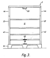
- Figure 3 is a front view of the apparatus as shown in Figure 1 but without a strap forming part of the auxiliary discharge means.
Claims (10)
Priority Applications (1)
| Application Number | Priority Date | Filing Date | Title |
|---|---|---|---|
| AT90305304T ATE87583T1 (en) | 1989-07-07 | 1990-05-16 | COLLAPSIBLE CONTAINER FOR USE IN STORING AND TRANSPORTING LIQUID MATERIAL. |
Applications Claiming Priority (2)
| Application Number | Priority Date | Filing Date | Title |
|---|---|---|---|
| GB8915650 | 1989-07-07 | ||
| GB898915650A GB8915650D0 (en) | 1989-07-07 | 1989-07-07 | Container apparatus for use in the storage and transportation of fluid materials |
Publications (2)
| Publication Number | Publication Date |
|---|---|
| EP0407018A1 true EP0407018A1 (en) | 1991-01-09 |
| EP0407018B1 EP0407018B1 (en) | 1993-03-31 |
Family
ID=10659713
Family Applications (1)
| Application Number | Title | Priority Date | Filing Date |
|---|---|---|---|
| EP90305304A Expired - Lifetime EP0407018B1 (en) | 1989-07-07 | 1990-05-16 | Collapsible container apparatus for use in the storage and transportation of fluid material |
Country Status (15)
| Country | Link |
|---|---|
| US (1) | US5100026A (en) |
| EP (1) | EP0407018B1 (en) |
| JP (1) | JP2930672B2 (en) |
| CN (1) | CN1023307C (en) |
| AT (1) | ATE87583T1 (en) |
| AU (1) | AU629496B2 (en) |
| CA (1) | CA2018953C (en) |
| DE (1) | DE69001209T2 (en) |
| DK (1) | DK0407018T3 (en) |
| ES (1) | ES2040561T3 (en) |
| GB (2) | GB8915650D0 (en) |
| IL (1) | IL94336A (en) |
| IN (1) | IN175095B (en) |
| NZ (1) | NZ233741A (en) |
| ZA (1) | ZA903917B (en) |
Cited By (2)
| Publication number | Priority date | Publication date | Assignee | Title |
|---|---|---|---|---|
| EP0461874A2 (en) * | 1990-06-15 | 1991-12-18 | Concertainer Limited | Container apparatus for the storage and transportation of fluid material |
| WO2003033380A2 (en) * | 2001-10-19 | 2003-04-24 | Peter Jeffrey Farrell | Collapsible container apparatus for use in the storage and transportation of fluid material |
Families Citing this family (8)
| Publication number | Priority date | Publication date | Assignee | Title |
|---|---|---|---|---|
| US5706872A (en) * | 1996-03-19 | 1998-01-13 | Schlesinger; Sol | Collapsible container for bulk transport and handling of heat meltable materials |
| US5746343A (en) * | 1996-11-27 | 1998-05-05 | Hoover Group, Inc. | Flexible bag for liquids mounted on a frame |
| US6089406A (en) * | 1999-06-01 | 2000-07-18 | Server Products | Packaged food warmer and dispenser |
| CN100418858C (en) * | 2006-02-16 | 2008-09-17 | 金永焕 | Folding water storage tank |
| WO2008116253A1 (en) * | 2007-03-23 | 2008-10-02 | Jonathan Lex Moodie | Collapsible water tank |
| SG152069A1 (en) * | 2007-10-09 | 2009-05-29 | Dragon Energy Pte Ltd | Hydroelectric system |
| US20110226763A1 (en) * | 2010-03-19 | 2011-09-22 | German Valencia | Folding container |
| DE102013205688A1 (en) * | 2013-03-28 | 2014-10-02 | Protechna S.A. | Inner container made of plastic as well as transport and storage containers for liquids with such an inner container |
Citations (2)
| Publication number | Priority date | Publication date | Assignee | Title |
|---|---|---|---|---|
| US4541765A (en) * | 1983-05-18 | 1985-09-17 | Wills Trucking, Inc. | Trailer unloading apparatus and method |
| GB2189773A (en) * | 1986-04-28 | 1987-11-04 | Farrell Containers Limited | Container apparatus for fluid material |
Family Cites Families (8)
| Publication number | Priority date | Publication date | Assignee | Title |
|---|---|---|---|---|
| US2858051A (en) * | 1955-06-20 | 1958-10-28 | Us Rubber Co | Apparatus for use in emptying collapsible containers |
| US3058623A (en) * | 1959-11-04 | 1962-10-16 | Thomas F Hawk | Storage bin |
| US4092051A (en) * | 1976-05-05 | 1978-05-30 | The Budd Company | Multi-purpose freight vehicle |
| AU543731B2 (en) * | 1980-08-21 | 1985-05-02 | Technosearch Pty. Limited | Controlling flow of particulate material |
| US4421250A (en) * | 1981-04-27 | 1983-12-20 | Bonerb Timothy C | Bin for free flowing material |
| EP0237260B1 (en) * | 1986-03-10 | 1989-12-20 | Solly Katz | Fluid dispenser |
| US4722655A (en) * | 1987-04-03 | 1988-02-02 | Bonerb Timothy C | Bulk storage bin for freight vehicle or other storage facility |
| US4861215A (en) * | 1987-04-03 | 1989-08-29 | Flexair, Inc. | Bulk storage bin with pneumatically assisted discharge |
-
1989
- 1989-07-07 GB GB898915650A patent/GB8915650D0/en active Pending
-
1990
- 1990-05-09 IL IL94336A patent/IL94336A/en not_active IP Right Cessation
- 1990-05-16 AT AT90305304T patent/ATE87583T1/en active
- 1990-05-16 DE DE9090305304T patent/DE69001209T2/en not_active Expired - Fee Related
- 1990-05-16 IN IN375MA1990 patent/IN175095B/en unknown
- 1990-05-16 GB GB9010906A patent/GB2233630B/en not_active Expired - Fee Related
- 1990-05-16 ES ES199090305304T patent/ES2040561T3/en not_active Expired - Lifetime
- 1990-05-16 DK DK90305304.9T patent/DK0407018T3/en active
- 1990-05-16 EP EP90305304A patent/EP0407018B1/en not_active Expired - Lifetime
- 1990-05-21 NZ NZ233741A patent/NZ233741A/en unknown
- 1990-05-21 ZA ZA903917A patent/ZA903917B/en unknown
- 1990-05-31 US US07/531,320 patent/US5100026A/en not_active Expired - Fee Related
- 1990-06-13 CA CA002018953A patent/CA2018953C/en not_active Expired - Fee Related
- 1990-06-20 CN CN90104494A patent/CN1023307C/en not_active Expired - Fee Related
- 1990-06-27 AU AU57925/90A patent/AU629496B2/en not_active Ceased
- 1990-07-06 JP JP2177677A patent/JP2930672B2/en not_active Expired - Fee Related
Patent Citations (2)
| Publication number | Priority date | Publication date | Assignee | Title |
|---|---|---|---|---|
| US4541765A (en) * | 1983-05-18 | 1985-09-17 | Wills Trucking, Inc. | Trailer unloading apparatus and method |
| GB2189773A (en) * | 1986-04-28 | 1987-11-04 | Farrell Containers Limited | Container apparatus for fluid material |
Cited By (4)
| Publication number | Priority date | Publication date | Assignee | Title |
|---|---|---|---|---|
| EP0461874A2 (en) * | 1990-06-15 | 1991-12-18 | Concertainer Limited | Container apparatus for the storage and transportation of fluid material |
| EP0461874A3 (en) * | 1990-06-15 | 1992-07-22 | Concertainer Limited | Container apparatus for the storage and transportation of fluid material |
| WO2003033380A2 (en) * | 2001-10-19 | 2003-04-24 | Peter Jeffrey Farrell | Collapsible container apparatus for use in the storage and transportation of fluid material |
| WO2003033380A3 (en) * | 2001-10-19 | 2003-08-21 | Peter Jeffrey Farrell | Collapsible container apparatus for use in the storage and transportation of fluid material |
Also Published As
| Publication number | Publication date |
|---|---|
| GB2233630B (en) | 1991-12-04 |
| GB8915650D0 (en) | 1989-08-23 |
| NZ233741A (en) | 1992-12-23 |
| IL94336A (en) | 1993-06-10 |
| IN175095B (en) | 1995-04-29 |
| CA2018953A1 (en) | 1991-01-07 |
| ATE87583T1 (en) | 1993-04-15 |
| CA2018953C (en) | 2001-04-10 |
| EP0407018B1 (en) | 1993-03-31 |
| DK0407018T3 (en) | 1995-03-13 |
| GB9010906D0 (en) | 1990-07-04 |
| IL94336A0 (en) | 1991-03-10 |
| AU629496B2 (en) | 1992-10-01 |
| GB2233630A (en) | 1991-01-16 |
| ES2040561T3 (en) | 1993-10-16 |
| US5100026A (en) | 1992-03-31 |
| ZA903917B (en) | 1991-03-27 |
| DE69001209T2 (en) | 1993-08-19 |
| AU5792590A (en) | 1991-01-10 |
| JPH0343382A (en) | 1991-02-25 |
| JP2930672B2 (en) | 1999-08-03 |
| CN1049134A (en) | 1991-02-13 |
| DE69001209D1 (en) | 1993-05-06 |
| CN1023307C (en) | 1993-12-29 |
Similar Documents
| Publication | Publication Date | Title |
|---|---|---|
| EP0573230B1 (en) | Container apparatus for fluid material | |
| US5636764A (en) | Flexible bulk container apparatus and discharge method | |
| US4781472A (en) | Large bag with liner | |
| US5192134A (en) | Re-usable flexible bulk containers | |
| US5340218A (en) | Bulk storage bag with remotely openable discharge spout | |
| US4573204A (en) | Slide fastener for flexible bulk container | |
| US3961655A (en) | Bulk material containers | |
| US4823979A (en) | Trash container | |
| CA1331448C (en) | Container apparatus for fluid material | |
| US3779157A (en) | Receptacle for waste material | |
| CA1309990C (en) | Receptacle having improved hopper | |
| EP0407018B1 (en) | Collapsible container apparatus for use in the storage and transportation of fluid material | |
| US3938731A (en) | Receptacle for waste material | |
| AU2002213503B2 (en) | Bulk bag with remote discharge | |
| US6415713B1 (en) | Rigid liner for a yard refuse bag | |
| US5529393A (en) | Flexible bulk container with disposable liner | |
| AU2002213503A1 (en) | Bulk bag with remote discharge | |
| US20020164093A1 (en) | Container with repositionable slip-sheet to cover outlet | |
| GB2297740A (en) | Container apparatus for fluid materials | |
| WO1996041754A2 (en) | Collapsible bin-type for bulk materials | |
| JPH08230900A (en) | Container device for fluid | |
| EP0461874A2 (en) | Container apparatus for the storage and transportation of fluid material | |
| US4946091A (en) | Collapsible container having congruent door retaining means | |
| WO2005115881A1 (en) | A load control waste/recycle container | |
| US20230182995A1 (en) | Flexible intermediate bulk container with collection skirt |
Legal Events
| Date | Code | Title | Description |
|---|---|---|---|
| PUAI | Public reference made under article 153(3) epc to a published international application that has entered the european phase |
Free format text: ORIGINAL CODE: 0009012 |
|
| AK | Designated contracting states |
Kind code of ref document: A1 Designated state(s): AT BE CH DE DK ES FR GR IT LI LU NL SE |
|
| 17P | Request for examination filed |
Effective date: 19910708 |
|
| 17Q | First examination report despatched |
Effective date: 19920504 |
|
| GRAA | (expected) grant |
Free format text: ORIGINAL CODE: 0009210 |
|
| AK | Designated contracting states |
Kind code of ref document: B1 Designated state(s): AT BE CH DE DK ES FR GR IT LI LU NL SE |
|
| REF | Corresponds to: |
Ref document number: 87583 Country of ref document: AT Date of ref document: 19930415 Kind code of ref document: T |
|
| ITF | It: translation for a ep patent filed |
Owner name: ING. C. GREGORJ S.P.A. |
|
| REF | Corresponds to: |
Ref document number: 69001209 Country of ref document: DE Date of ref document: 19930506 |
|
| ET | Fr: translation filed | ||
| REG | Reference to a national code |
Ref country code: GR Ref legal event code: FG4A Free format text: 3008315 |
|
| REG | Reference to a national code |
Ref country code: ES Ref legal event code: FG2A Ref document number: 2040561 Country of ref document: ES Kind code of ref document: T3 |
|
| PLBE | No opposition filed within time limit |
Free format text: ORIGINAL CODE: 0009261 |
|
| STAA | Information on the status of an ep patent application or granted ep patent |
Free format text: STATUS: NO OPPOSITION FILED WITHIN TIME LIMIT |
|
| 26N | No opposition filed | ||
| EPTA | Lu: last paid annual fee | ||
| EAL | Se: european patent in force in sweden |
Ref document number: 90305304.9 |
|
| REG | Reference to a national code |
Ref country code: DK Ref legal event code: T3 |
|
| PGFP | Annual fee paid to national office [announced via postgrant information from national office to epo] |
Ref country code: LU Payment date: 20000515 Year of fee payment: 11 |
|
| PGFP | Annual fee paid to national office [announced via postgrant information from national office to epo] |
Ref country code: DK Payment date: 20000523 Year of fee payment: 11 |
|
| PGFP | Annual fee paid to national office [announced via postgrant information from national office to epo] |
Ref country code: AT Payment date: 20000530 Year of fee payment: 11 |
|
| PGFP | Annual fee paid to national office [announced via postgrant information from national office to epo] |
Ref country code: GR Payment date: 20000531 Year of fee payment: 11 |
|
| PGFP | Annual fee paid to national office [announced via postgrant information from national office to epo] |
Ref country code: CH Payment date: 20000808 Year of fee payment: 11 |
|
| PG25 | Lapsed in a contracting state [announced via postgrant information from national office to epo] |
Ref country code: LU Free format text: LAPSE BECAUSE OF NON-PAYMENT OF DUE FEES Effective date: 20010516 Ref country code: DK Free format text: LAPSE BECAUSE OF NON-PAYMENT OF DUE FEES Effective date: 20010516 Ref country code: AT Free format text: LAPSE BECAUSE OF NON-PAYMENT OF DUE FEES Effective date: 20010516 |
|
| PG25 | Lapsed in a contracting state [announced via postgrant information from national office to epo] |
Ref country code: GR Free format text: LAPSE BECAUSE OF NON-PAYMENT OF DUE FEES Effective date: 20010531 |
|
| PG25 | Lapsed in a contracting state [announced via postgrant information from national office to epo] |
Ref country code: LI Free format text: LAPSE BECAUSE OF NON-PAYMENT OF DUE FEES Effective date: 20010615 Ref country code: CH Free format text: LAPSE BECAUSE OF NON-PAYMENT OF DUE FEES Effective date: 20010615 |
|
| REG | Reference to a national code |
Ref country code: CH Ref legal event code: PL |
|
| REG | Reference to a national code |
Ref country code: DK Ref legal event code: EBP |
|
| PGFP | Annual fee paid to national office [announced via postgrant information from national office to epo] |
Ref country code: SE Payment date: 20020513 Year of fee payment: 13 |
|
| PGFP | Annual fee paid to national office [announced via postgrant information from national office to epo] |
Ref country code: BE Payment date: 20020516 Year of fee payment: 13 |
|
| PGFP | Annual fee paid to national office [announced via postgrant information from national office to epo] |
Ref country code: ES Payment date: 20020521 Year of fee payment: 13 |
|
| PGFP | Annual fee paid to national office [announced via postgrant information from national office to epo] |
Ref country code: FR Payment date: 20020529 Year of fee payment: 13 |
|
| PGFP | Annual fee paid to national office [announced via postgrant information from national office to epo] |
Ref country code: NL Payment date: 20020531 Year of fee payment: 13 |
|
| PGFP | Annual fee paid to national office [announced via postgrant information from national office to epo] |
Ref country code: DE Payment date: 20020730 Year of fee payment: 13 |
|
| PG25 | Lapsed in a contracting state [announced via postgrant information from national office to epo] |
Ref country code: SE Free format text: LAPSE BECAUSE OF NON-PAYMENT OF DUE FEES Effective date: 20030517 Ref country code: ES Free format text: LAPSE BECAUSE OF NON-PAYMENT OF DUE FEES Effective date: 20030517 |
|
| PG25 | Lapsed in a contracting state [announced via postgrant information from national office to epo] |
Ref country code: BE Free format text: LAPSE BECAUSE OF NON-PAYMENT OF DUE FEES Effective date: 20030531 |
|
| BERE | Be: lapsed |
Owner name: *CONCERTAINER LTD Effective date: 20030531 |
|
| PG25 | Lapsed in a contracting state [announced via postgrant information from national office to epo] |
Ref country code: NL Free format text: LAPSE BECAUSE OF NON-PAYMENT OF DUE FEES Effective date: 20031201 |
|
| PG25 | Lapsed in a contracting state [announced via postgrant information from national office to epo] |
Ref country code: DE Free format text: LAPSE BECAUSE OF NON-PAYMENT OF DUE FEES Effective date: 20031202 |
|
| EUG | Se: european patent has lapsed | ||
| PG25 | Lapsed in a contracting state [announced via postgrant information from national office to epo] |
Ref country code: FR Free format text: LAPSE BECAUSE OF NON-PAYMENT OF DUE FEES Effective date: 20040130 |
|
| NLV4 | Nl: lapsed or anulled due to non-payment of the annual fee |
Effective date: 20031201 |
|
| REG | Reference to a national code |
Ref country code: FR Ref legal event code: ST |
|
| REG | Reference to a national code |
Ref country code: ES Ref legal event code: FD2A Effective date: 20030517 |
|
| PG25 | Lapsed in a contracting state [announced via postgrant information from national office to epo] |
Ref country code: IT Free format text: LAPSE BECAUSE OF NON-PAYMENT OF DUE FEES;WARNING: LAPSES OF ITALIAN PATENTS WITH EFFECTIVE DATE BEFORE 2007 MAY HAVE OCCURRED AT ANY TIME BEFORE 2007. THE CORRECT EFFECTIVE DATE MAY BE DIFFERENT FROM THE ONE RECORDED. Effective date: 20050516 |