EP0406635B1 - Dental cuspidor system - Google Patents
Dental cuspidor system Download PDFInfo
- Publication number
- EP0406635B1 EP0406635B1 EP90111808A EP90111808A EP0406635B1 EP 0406635 B1 EP0406635 B1 EP 0406635B1 EP 90111808 A EP90111808 A EP 90111808A EP 90111808 A EP90111808 A EP 90111808A EP 0406635 B1 EP0406635 B1 EP 0406635B1
- Authority
- EP
- European Patent Office
- Prior art keywords
- installation according
- valve
- servovalve
- valve body
- servomotor
- Prior art date
- Legal status (The legal status is an assumption and is not a legal conclusion. Google has not performed a legal analysis and makes no representation as to the accuracy of the status listed.)
- Expired - Lifetime
Links
- XLYOFNOQVPJJNP-UHFFFAOYSA-N water Substances O XLYOFNOQVPJJNP-UHFFFAOYSA-N 0.000 claims abstract description 23
- 238000011144 upstream manufacturing Methods 0.000 claims abstract description 6
- 238000009434 installation Methods 0.000 claims description 46
- 239000002351 wastewater Substances 0.000 claims description 25
- 238000013022 venting Methods 0.000 claims description 2
- 238000010079 rubber tapping Methods 0.000 claims 2
- 238000002347 injection Methods 0.000 claims 1
- 239000007924 injection Substances 0.000 claims 1
- 229910000497 Amalgam Inorganic materials 0.000 description 31
- 238000011161 development Methods 0.000 description 15
- 230000018109 developmental process Effects 0.000 description 15
- 230000006835 compression Effects 0.000 description 8
- 238000007906 compression Methods 0.000 description 8
- 239000007788 liquid Substances 0.000 description 8
- 239000002245 particle Substances 0.000 description 7
- 238000000926 separation method Methods 0.000 description 7
- 238000007789 sealing Methods 0.000 description 6
- 210000003296 saliva Anatomy 0.000 description 5
- 239000007787 solid Substances 0.000 description 5
- 230000004888 barrier function Effects 0.000 description 3
- 230000033001 locomotion Effects 0.000 description 3
- 239000012528 membrane Substances 0.000 description 3
- 239000000203 mixture Substances 0.000 description 3
- 235000014676 Phragmites communis Nutrition 0.000 description 2
- 210000004369 blood Anatomy 0.000 description 2
- 239000008280 blood Substances 0.000 description 2
- 230000008859 change Effects 0.000 description 2
- 239000000470 constituent Substances 0.000 description 2
- 238000011109 contamination Methods 0.000 description 2
- 239000010865 sewage Substances 0.000 description 2
- 230000008901 benefit Effects 0.000 description 1
- 230000005540 biological transmission Effects 0.000 description 1
- 230000000295 complement effect Effects 0.000 description 1
- 239000000356 contaminant Substances 0.000 description 1
- 239000000498 cooling water Substances 0.000 description 1
- 230000007423 decrease Effects 0.000 description 1
- 210000004268 dentin Anatomy 0.000 description 1
- 238000010586 diagram Methods 0.000 description 1
- 230000000694 effects Effects 0.000 description 1
- 239000012530 fluid Substances 0.000 description 1
- 230000001771 impaired effect Effects 0.000 description 1
- 230000006872 improvement Effects 0.000 description 1
- 239000012535 impurity Substances 0.000 description 1
- 230000002452 interceptive effect Effects 0.000 description 1
- 230000007774 longterm Effects 0.000 description 1
- 239000000463 material Substances 0.000 description 1
- 230000007246 mechanism Effects 0.000 description 1
- 210000003097 mucus Anatomy 0.000 description 1
- 238000005192 partition Methods 0.000 description 1
- 238000005086 pumping Methods 0.000 description 1
- 230000007704 transition Effects 0.000 description 1
Images


Classifications
-
- A—HUMAN NECESSITIES
- A61—MEDICAL OR VETERINARY SCIENCE; HYGIENE
- A61C—DENTISTRY; APPARATUS OR METHODS FOR ORAL OR DENTAL HYGIENE
- A61C17/00—Devices for cleaning, polishing, rinsing or drying teeth, teeth cavities or prostheses; Saliva removers; Dental appliances for receiving spittle
- A61C17/06—Saliva removers; Accessories therefor
- A61C17/065—Saliva removers; Accessories therefor characterised by provisions for processing the collected matter, e.g. for separating solids or air
Definitions
- the invention relates to a bowl installation according to the preamble of claim 1.
- a housing is connected to the water pipe coming from the cuspidor, which limits a waste water collection chamber.
- An opening is provided in one of the side walls of the waste water chamber, which opening can be closed by the plate of a servo valve, which is arranged next to the waste water collecting housing.
- the servo valve is controlled by a diaphragm pressure sensor which forms a wall of the waste water collecting chamber opposite the outlet opening. If a predetermined pressure in the wastewater collection chamber is exceeded, the servo valve is opened and opens a double angled flow path to an outlet port of the servo valve, to which a further section of the wastewater line is connected, which leads to a disposal connection of the house installation.
- amalgam separation units which usually contain a centrifuge. This centrifuge is connected to the mouth suction on the inlet side and is therefore under negative pressure.
- Classic bowl installations without a servo valve inserted in the sewage pipe can therefore not be connected to the amalgam separator unit.
- the present invention is intended to provide a cuspidor installation which can be connected to an amalgam separator unit under pressure without interfering with its work, with a large change in the flow cross section being obtained with a relatively small path of the valve body.
- the servo valve can be opened quickly to a large flow cross section, so that a large water flow rate of typically about 4 l / min is achieved.
- the flow connection between the cuspidor and the wastewater line (which is connected to the inlet of the amalgam separating unit in the operational state) is normally blocked.
- the vacuum at the inlet of the amalgam separation unit is thus not affected; separating the very fine amalgam particles, which are sucked out of the patient's mouth, are produced with the desired high degree of separation.
- the fact that the flow connection between the bowl and the sewage pipe is normally interrupted also means that there is no noise caused by gurgling water, as would otherwise be the case when sucking air through pipes partially filled with water. If a larger mass of water has accumulated in front of the servo valve, it is quickly sucked off to the amalgam separating unit after opening the servo valve. As soon as this amount of water is removed, the servo valve closes again quickly. Since the bowl is used regularly when the dentist is not working, the short-term change in the pressure conditions at the inlet of the amalgam separation unit has no effect on the dentist's work.
- the column height sensor can be integrated into the housing of the servo valve itself or can be attached directly to it.
- the cuspidor installation has a compact structure and is particularly easy to install.
- the servo valve can be controlled using level detectors, which are available very inexpensively, for example in the form of float switches.
- level detectors which are available very inexpensively, for example in the form of float switches.
- the height of the water column at which the column height sensor responds can also be adjusted particularly simply and clearly.
- a vacuum source can be used which only provides a low vacuum but has a large pumping capacity.
- a pressure ratio is obtained on the spot and can thus generate a high negative pressure in the servomotor. This in turn makes it possible to bias the valve body of the servo valve into the closed position with a relatively large spring force, so that the servo valve seals well.
- the vacuum for moving the servo valve servomotor can be tapped directly from the outlet of the servo valve, which is connected to the vacuum-pressurized inlet of the amalgam separating unit in the ready state. This makes such a bowl installation particularly compact.
- the servo valve is actuated using electrical energy. This has the advantage that the servomotor of the servo valve does not come into contact with possibly contaminated fluid, so that hygiene is ensured even in long-term operation.
- valve body with only low inherent rigidity can also be used, but at the same time an exact guiding of the valve body in the opening or closing direction is ensured.
- valve body has low mass, so it can be moved quickly and easily between its working positions.
- the bellows placed on the upper end of the valve body also fulfills the function of a diaphragm motor.
- the suction device of the dental work station can be forcibly started via the additionally provided electrical contact if a larger amount of water is added to the cuspidor, but the suction machine itself is just switched off because the saliva lifter and the suction pipe are on the shelf is laid.
- the number of opening and closing operations of the servo valve is reduced, since in addition to the volume of the line part connected to the input of the servo valve, the volume of the storage tank for storing waste water between two opening cycles of the servo valve is available. Infrequent opening of the servo valve is advantageous in view of the low wear of the same and in view of low noise pollution.
- the development of the invention according to claim 24 is advantageous with regard to reliable operation of the venting valve, which is positively controlled by a float, even under the difficult operating conditions such as the highly contaminated wastewater from a dental workplace.
- the float is easy to move, yet guided, and deposits on the walls of the storage container in the area of the float do not lead to any appreciably increased friction, but are continually scraped off by these in the form of the spherical projections.
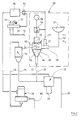
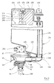
- FIG. 1 shows a cuspidor 10 of a dental work station, which is connected via a line 12, a servo valve, generally designated 14, and a line 16 to an amalgam separation unit, generally designated 18.
- the latter releases water freed from entrained amalgam particles to a line 20, which is connected to the public sewer network, and collects the amalgam particles and other solid parts of the wastewater supplied to them in a collecting container 22, which is exchanged at intervals for an empty collecting container.
- a suction pipe 24 for sucking cooling water out of the patient's mouth and a saliva siphon 26 are shown hanging on a shelf 28. These suction means are connected via a line 30 to the inlet of a cyclone 32, in which liquid portions of the extracted mixture are separated. These liquid components accumulated at the bottom of the cyclone 32 also reach the inlet of the amalgam separating unit 18 via a line 34.
- the air outlet of the cyclone 32 is connected via a line 36 to the suction connection of a suction machine designated overall by 38. This gives the sucked air to one Line 40, which is guided over the roof.
- the servo valve 14 has a frustoconical valve seat surface 42 which cooperates with a frustoconical valve body 44.
- the housing of the servo valve 14, designated 46, carries an inlet connection 48 and an outlet connection 50, and a pressure sensor 52 is arranged on the inlet connection 48. Roughly speaking, this works so that it generates an output signal when the liquid column in line 12 exceeds a height H 1, the sensor output signal being terminated when the height of the water column falls below a value H 2.
- the output signal of the pressure sensor 52 actuates a controllable switch 54, via which a servomotor 56 of the servo valve can be connected to an energy source 58.
- the servomotor 56 operates on a valve stem 60 which is connected to the valve body 44.
- a helical compression spring 62 serves to bias the valve body 44 into the closed position.
- the output signal of the pressure sensor 52 is also passed to a first input of an OR gate 64, the second input of which is then acted upon from the storage 28 by sensors integrated into this, not shown, when either the suction tube 24 or the saliva lifter 26 from the tray 28 is lifted off.
- the output signal of the OR gate 64 drives a power circuit 66, via which the amalgam separation unit 18 and the suction machine 38 are supplied with energy.
- the wastewater disposal shown in FIG. 1 for a dental work station in which the elements 10, 14 and 50 to 58 as a whole constitute a bowl assembly 68, works as follows: If the suction tube 24 or the saliva lifter 26 is removed from the rest 28 (dentist works in the patient's mouth), the amalgam separating unit 18 and the suction machine 38 are started. The mixture of air, water, saliva, blood, dentrin and amalgam particles sucked out of the patient's mouth first reaches the cyclone 32. The lower part collects the liquid and solid constituents which pass from there into the amalgam separation unit 18. This passes the liquid components on to the line 20, the solid components come into the collecting container 22.
- the pressure sensor 52 responds. If the amalgam separator unit 18 and suction machine 38 are not already running anyway, they are set in motion by the output signal of the pressure sensor 52.
- Switch 54 is also closed by the output signal of pressure sensor 52, and servomotor 56 now lifts valve body 44 from valve seat surface 42.
- the volume of water in the line 12 is now rapidly drawn through the servo valve 14 into the amalgam separating unit 18 by the negative pressure at the inlet of the amalgam separating unit 18.
- Typical throughput rates in the open position of the servo valve are approximately 4 l / min.
- the height H of the water column standing in the line 12 thus decreases rapidly, and when the height H 2 is reached, the pressure sensor 52 ends its output signal, and the valve body 44 returns under the force of the helical compression spring 62 into the closed position.
- the water sucked out of the line 12 via the servo valve 14 is equally freed from solid constituents in the amalgam separating unit 18 and then gets into the line 20th
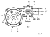
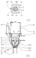
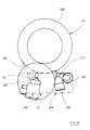
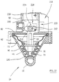
- FIGS 2 to 5 show details of a first practical embodiment of a servo valve 14 with attached pressure sensor 52. Components that have already been explained above with reference to Figure 1 are again provided with the same reference numerals and need not be explained again in detail.
- valve body 44 is a one-piece molded part made of elastically deformable material.
- a corrugated bellows section 72 adjoins a conical lower control head 70.
- the control head 70 is provided with a lip 74, the outer edge of which, in the unloaded state, projects somewhat beyond the conical surface provided by the control head 70. In this way, particularly good sealing properties of the servo valve are obtained in the closed position.
- a spring seat plate 76 which is connected to the valve stem 60, is clipped into the transition section between the control head 70 and the bellows section 72. As can be seen from the drawing, the latter has a cross-shaped cross section.
- the lower end of the valve stem 60 is designed as a pin 78 which engages axially displaceably in a blind bore 80 which on the inside of the lower end of the Valve body 44 is provided.
- the spring seat plate 76 can move the lip 74 in tight contact against the valve seat surface 42 when the main surface of the control head 70 is already in contact with the valve seat surface 42.
- a cover 82 of the housing 46 has a groove-shaped recess 84, which on the one hand serves as a spring seat for the upper end of the helical compression spring 62, and also creates a flow connection between a first connection piece 86 and a second connection piece 88, both of which are molded onto the cover 82 . Between the connection piece 86, 88, a guide piece 90 of the housing 46 is pulled up, in which the valve stem 60 runs.
- connection stub 92 is formed, via which the interior of the bellows section 72 can be pressurized in order to lift the control head 70 against the force of the helical compression spring 62 from the valve seat surface 42.
- a tap neck 94 is formed on the outlet neck 50 and has an end section 96 running downward in the outlet neck 50.
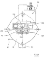
- the pressure sensor 52 has a sensor piston 98, which is seated on a piston shaft 100, which runs in a guide bore 102 in the sensor housing 104.
- a flexible membrane 106 is provided to seal the sensor piston 98 against the interior of the inlet connection 48.
- the sensor piston 98 is biased downward in the drawing by a helical compression spring 108 and can be raised to the position shown in FIG. 4 by pressurization.
- Transverse injector channel 110 provided in the piston skirt 100 has an intake funnel 112 with a working nozzle 114. The latter is connected to the nozzle 94 via a line 116, the two connecting nozzles 86, 88 and the recess 84.
- a connecting groove 118 is provided which leads to a suction port 120. This suction port is connected to the connection port 92 via a line 122.
- the piston skirt 100 has dropped so far that the injector channel 110 is no longer aligned with the suction funnel 112, as a result of which the negative pressure on the bellows section 72 is ended.
- the valve body 44 thus returns to the closed position under the force of the helical compression spring 62.
- the piston shaft 100 carries an annular permanent magnet 124 which cooperates with a reed contact placed on the sensor housing 104. This reed contact is then inserted between a voltage source and the assigned input of the OR gate 64.
- a baffle 128 is arranged under the membrane 106.
- valve parts which have already been described above with reference to FIGS. 2 to 5 in functionally equivalent form are again provided with the same reference symbols. They do not need to be described again in detail below.
- the control head 70 now carries five axially spaced lips 130-1 to 130-5, which cooperate with the valve seat surface 42.
- the vacuum actuated valve servomotor is now replaced by an electromagnet 132 which can be connected to a low-voltage source via the switch 54, which is now designed as an electrical switch.
- the cover 82 of the housing 46 of the servo valve 14 also carries a connecting piece 134 to which a conventional pressure switch can be connected via a hose.
- a single-acting compressed air working cylinder can be used instead of the electromagnet 132 shown in FIG. 6, or a double-acting compressed air working cylinder can be provided instead of the electromagnet 132 and the helical compression spring 62.
- the control of the connection between the working spaces of these working cylinders and a compressed air source or atmosphere can be carried out similarly to the application of vacuum to the bellows section 72 in the exemplary embodiment according to FIGS. 3 and 4, that is to say fluidically, or using a solenoid valve.
- a branch from a compressed air line already present at the treatment station can serve as the compressed air source.
- a solenoid valve 136 is connected to the vacuum connecting piece 92, which is connected on the outlet side to a hollow guide rod 138 on which the valve body 44 is guided.
- the guide rod 138 is provided on its outside with longitudinal grooves 140, and in this way the upper side of a membrane section 72 'of the control head 70, which replaces the bellows section 72 of the exemplary embodiment according to FIGS. 2 to 5, can be subjected to negative pressure.
- This vacuum application begins when the solenoid valve 136 is opened and ends when the energization of the solenoid valve 136 is ended.
- the inlet connection 48 is oriented vertically upward and, separated from it by a vertical partition, a connection connection 134 is again provided, to which a pressure sensor controlling the operation of the solenoid valve 136 can be connected.
- a servo valve 14 is used, which largely corresponds to the servo valve according to FIG. 7 in terms of its flow structure.
- the corresponding valve parts are again provided with the same reference symbols.
- An angled intermediate piece 144 is attached to the horizontally oriented inlet connection 48, its inlet connection 146 lying behind the plane of the drawing in FIG the line 12 coming from the cuspidor is connected.
- a second, vertically extending connecting piece 148 of the intermediate piece 144 receives a lower connecting piece 150, which is molded onto the inclined bottom wall 152 of a storage container designated overall by 154.
- the bottom wall 152 has a step 156, so that the bottom wall is overall adapted to the outer contour of the servo valve 14.
- the storage container 154 has a rectangular prismatic cross-section, with an upper container section being drawn in, as shown at 158.
- a float switch 160 is arranged, which is connected to the nozzle 148 via a pipe 162.
- the retracted container section 158 itself again has a rectangular prismatic cross section and surrounds a float 164 at a small distance.
- the latter has knobs 166 on its outside, via which the float 164 in the container section 158 is easily guided.
- the float 164 has a central bore 168 into which a holding rod 170 is clipped.
- the holding rod 170 has a cross-shaped rod end portion 172 which runs in an opening 174 which is provided in the upper wall of the storage container. Radially protruding tabs 176 limit the downward movement of the holding rod 170.
- a sealing washer 178 is attached, which can seal the lower edge of the opening 174 when the float 164 is raised accordingly far.
- the float switch 160 switches so early that the sealing disk 178 has not yet been raised to the lower edge of the opening 174. However, if the servo valve 14 or the float switch 160 is not working correctly, the level of the waste water inside the storage tank 154 continues to rise, the float 164 is raised and the sealing disk 178 closes the opening 174. This means that no further waste water can enter the storage tank 154 flow. The incorrect functioning of the valve / storage unit can then be recognized by the water backing up into the bowl. Contaminated waste water does not flow out of the storage tank 154, however, even under such disturbance conditions.
- the outlet connection of the servo valve 14 is connected via a pipe bracket 180 to an inlet connection 182 of the amalgam separating unit 18, which is only schematically indicated in FIG. 10 and which generally comprises a centrifuge 184.
- a support body generally designated 186, is provided in the interior of the hollow valve body 44, which is molded onto the spring seat plate 76 or plugged onto it.
- the support body 186 has a rod-shaped end section 188 which engages in a complementary blind bore 190 in the bottom of the valve body 44.
- a frustoconical support portion 192 is spaced parallel behind the inner surface of the valve body 44 and carries two circumferential support ribs 194, 196 which are midway between the lips 130-3 and 130-4 or 130-4 and 130-5 of the valve body 44 lie. This way you get in the larger radius portion of the hollow control head 70, in which the control head is less stable, improves lip support in the radial direction. Since the support ribs 194, 196 lie between these lips, the latter can still dodge if there is a larger amalgam lump or the like between them and the valve seat surface.
- the float 164 is now arranged in the storage container 154 so as to be pivotable about a horizontal axis 198.
- Inwardly projecting stop ribs 200 formed on the front and rear walls of the storage container 154 define a lowest position of the float 164.
- the holding rod 170 is fixedly attached to the float 164. Its end face also serves to actuate the plunger of a microswitch 202 which projects into the opening 174.
- the float 164 thus serves at the same time to close the opening 174 through the sealing washer 178 and to actuate the microswitch 202 when the level of the waste water accumulated in the storage tank 154 reaches the level H 1.
- an upper section of the storage container 154 is designed as a removable cover 204.
- valve parts which have already been described above, in particular with reference to FIG. 3, have the same reference symbols Mistake.
- the valve stem 60 has a plate-shaped end section 206 which runs laterally in vertical guide grooves 208 which are provided on the inside of the guide stub 90.
- a transverse slot 210 is provided in the end section 206, in which a crank pin 212 is received. This is rotated by the output shaft 214 of an electric gear motor 216.
- One of the arms carries the crank pin 212 at the same time.
- the geared motor 216 is started in the opening direction when an output signal of the pressure sensor 52 indicating an exceeding of the maximum level H 1 is obtained, and stopped when the first output signal of the light barrier unit 220 is present thereafter.
- the opening stroke of the valve body 44 can be specified via the angle enclosed between the arms of the lever 218. If desired, this stroke can also be controlled by pure time control, e.g. a monostable flip-flop.
- the gear motor 216 is excited when the pressure sensor 52 provides a signal associated with the lower liquid level H2. The closing movement is ended with the first subsequently received output signal from the light barrier unit 220.
- crank mechanism not only serves for additional power transmission in the vicinity of the closed position of the valve body 44, it also allows the use of a simple, low-precision position transmitter for controlling the geared motor 216.
Landscapes
- Health & Medical Sciences (AREA)
- Dentistry (AREA)
- Epidemiology (AREA)
- Life Sciences & Earth Sciences (AREA)
- Animal Behavior & Ethology (AREA)
- General Health & Medical Sciences (AREA)
- Public Health (AREA)
- Veterinary Medicine (AREA)
- External Artificial Organs (AREA)
- Medicines Containing Plant Substances (AREA)
- Table Devices Or Equipment (AREA)
- Bidet-Like Cleaning Device And Other Flush Toilet Accessories (AREA)
- Dental Tools And Instruments Or Auxiliary Dental Instruments (AREA)
- Glass Compositions (AREA)
- Electrically Driven Valve-Operating Means (AREA)
- Indication Of The Valve Opening Or Closing Status (AREA)
- Apparatus For Radiation Diagnosis (AREA)
Abstract
Description
Die Erfindung betrifft eine Speischaleninstallation gemäß dem Oberbegriff des Anspruches 1.The invention relates to a bowl installation according to the preamble of claim 1.
Eine derartige Installation ist in der US-A-4 307 475 beschrieben. Bei ihr ist an die von der Speischale herkommende Wasserleitung ein Gehäuse angeschlossen, welches eine Abwasser-Sammelkammer begrenzt. In einer der Seitenwände der Abwasserkammer ist eine Öffnung vorgesehen, die durch den Teller eines Servoventiles verschließbar ist, welches neben dem Abwasser-Sammelgehäuse angeordnet ist. Die Steuerung des Servoventiles erfolgt durch einen Membran-Druckfühler, der eine der Auslaßöffnung gegenüberliegende Wand der Abwasser-Sammelkammer bildet. Wird ein vorgegebener Druck in der Abwasser-Sammelkammer überschritten, so wird das Servoventil aufgesteuert und gibt einen zweifach abgewinkelten Strömungspfad zu einem Auslaßstutzen des Servoventiles frei, an welchen ein weiterer Abschnitt der Abwasserleitung angeschlossen ist, der zu einem Entsorgungsanschluß der Hausinstallation führt.Such an installation is described in US-A-4,307,475. In this case, a housing is connected to the water pipe coming from the cuspidor, which limits a waste water collection chamber. An opening is provided in one of the side walls of the waste water chamber, which opening can be closed by the plate of a servo valve, which is arranged next to the waste water collecting housing. The servo valve is controlled by a diaphragm pressure sensor which forms a wall of the waste water collecting chamber opposite the outlet opening. If a predetermined pressure in the wastewater collection chamber is exceeded, the servo valve is opened and opens a double angled flow path to an outlet port of the servo valve, to which a further section of the wastewater line is connected, which leads to a disposal connection of the house installation.
Da das Abwasser im Servoventil starken Richtungsänderungen unterworfen ist und die Durchströmguerschnitte im Servoventil nur verhältnismäßig klein sind, besteht bei der eingangs erwähnten Speischaleninstallation die Gefahr, daß das Ventil durch feste Anteile des Abwassers verschmutzt und nicht mehr richtig schließt. Das von der Speischale abgegebene Wasser enthält nämlich auch Schleim, Blut, Dentin und Amalgampartikel, und für dieses Gemisch erfolgt stromauf des Servoventiles nur eine grobe Vorreinigung durch ein normalerweise bei der Speischale vorgesehenes Drahtsieb.Since the wastewater in the servo valve is subject to strong changes in direction and the flow cross-sections in the servo valve are only relatively small, there is a risk in the cuspidor installation mentioned at the outset that the valve is contaminated by solid portions of the wastewater and no longer closes properly. The water released from the bowl also contains mucus, blood, dentin and amalgam particles, and this mixture is only roughly pre-cleaned upstream of the servo valve by a wire sieve normally provided in the bowl.
Zunehmend wird heute gefordert, daß Amalgampartikel nicht mehr ins Abwasser gelangen dürfen. Zahnärztliche Arbeitsplätze werden daher heute mit Amalgamabscheideeinheiten ausgestattet, die in der Regel eine Zentrifuge enthalten. Diese Zentrifuge ist einlaßseitig mit der Mundabsaugung verbunden und steht deshalb unter Unterdruck. Klassische Speischaleninstallationen ohne in die Abwasserleitung eingefügtes Servoventil können daher nicht an die Amalgam-Abscheideeinheit angeschlossen werden.There is an increasing demand today that amalgam particles are no longer allowed to get into the wastewater. Dental workplaces are therefore now equipped with amalgam separation units, which usually contain a centrifuge. This centrifuge is connected to the mouth suction on the inlet side and is therefore under negative pressure. Classic bowl installations without a servo valve inserted in the sewage pipe can therefore not be connected to the amalgam separator unit.
Durch die vorliegende Erfindung soll eine Speischaleninstallation geschaffen werden, die an eine unterdruckbeaufschlagte Amalgam-Abscheideeinheit angeschlossen werden kann, ohne deren Arbeiten zu beeinträchtigen, wobei bei verhältnismäßig kleinem Weg des Ventilkörpers eine große Änderung des Durchflußquerschnittes erhalten werden soll.The present invention is intended to provide a cuspidor installation which can be connected to an amalgam separator unit under pressure without interfering with its work, with a large change in the flow cross section being obtained with a relatively small path of the valve body.
Diese Aufgabe ist erfindungsgemäß gelöst durch eine Speischaleninstallation gemäß Anspruch 1.This object is achieved according to the invention by installing a cuspidor according to claim 1.
Bei der erfindungsgemäßen Speischaleninstallation kann das Servoventil rasch auf großen Durchflußquerschnitt geöffnet werden, so daß man eine große Wasser-Durchschleusmenge von typischerweise etwa 4 l/min erreicht.In the cuspidor installation according to the invention, the servo valve can be opened quickly to a large flow cross section, so that a large water flow rate of typically about 4 l / min is achieved.
Bei der erfindungsgemäßen Speischaleninstallation ist auch die Strömungsverbindung zwischen Speischale und Abwasserleitung (diese ist im betriebsbereiten Zustand an den Einlaß der Amalgam-Abscheideeinheit angeschlossen) normalerweise gesperrt. Das Vakuum am Einlaß der Amalgam-Abscheideeinheit wird somit nicht beeinträchtigt; das Abscheiden der sehr feinen Amalgampartikel, die aus dem Mund des Patienten direkt abgesaugt werden, erfolgt mit dem gewünschten hohen Abscheidegrad. Die Tatsache, daß die Strömungsverbindung zwischen Speischale und Abwasserleitung normalerweise unterbrochen ist, hat auch zur Folge, daß keine Geräuschbelästigung durch Glucksen von Wasser erhalten wird, wie dies sonst beim Hindurchsaugen von Luft durch teilweise mit Wasser gefüllte Leitungen der Fall wäre. Hat sich vor dem Servoventil eine größere Wassermasse angestaut, so wird diese nach Öffnen des Servoventiles rasch zur Amalgam-Abscheideeinheit hin abgesaugt. Sowie diese Wassermenge weggeschafft ist, schließt das Servoventil rasch wieder. Da das Benutzen der Speischale regelmäßig dann erfolgt, wenn der Zahnarzt nicht arbeitet, bleibt die kurzfristige Änderung der Druckverhältnisse am Einlaß der Amalgam-Abscheideeinheit ohne Auswirkung auf das Arbeiten des Zahnarztes.In the cuspidor installation according to the invention, the flow connection between the cuspidor and the wastewater line (which is connected to the inlet of the amalgam separating unit in the operational state) is normally blocked. The vacuum at the inlet of the amalgam separation unit is thus not affected; separating the very fine amalgam particles, which are sucked out of the patient's mouth, are produced with the desired high degree of separation. The fact that the flow connection between the bowl and the sewage pipe is normally interrupted also means that there is no noise caused by gurgling water, as would otherwise be the case when sucking air through pipes partially filled with water. If a larger mass of water has accumulated in front of the servo valve, it is quickly sucked off to the amalgam separating unit after opening the servo valve. As soon as this amount of water is removed, the servo valve closes again quickly. Since the bowl is used regularly when the dentist is not working, the short-term change in the pressure conditions at the inlet of the amalgam separation unit has no effect on the dentist's work.
Vorteilhafte Weiterbildungen der Erfindung sind in Unteransprüchen angegeben.Advantageous developments of the invention are specified in the subclaims.
Mit der Weiterbildung der Erfindung gemäß Anspruch 2 wird erreicht, daß der Säulenhöhenfühler in das Gehäuse des Servoventiles selbst integriert werden kann oder an dieses direkt angebaut werden kann. Die Speischaleninstallation erhält so kompakten Aufbau und läßt sich besonders einfach montieren.With the development of the invention according to claim 2 it is achieved that the column height sensor can be integrated into the housing of the servo valve itself or can be attached directly to it. The cuspidor installation has a compact structure and is particularly easy to install.
Mit der im Anspruch 3 angegebenen alternativen Lösung kann man das Steuern des Servoventiles unter Verwendung von Pegeldetektoren vornehmen, die z.B. in Form von Schwimmerschaltern sehr preisgünstig zur Verfügung stehen. Bei einer Installation gemäß Anspruch 3 läßt sich die Höhe der Wassersäule, bei welcher der Säulenhöhenfühler anspricht, auch besonders einfach und anschaulich einjustieren.With the alternative solution specified in claim 3, the servo valve can be controlled using level detectors, which are available very inexpensively, for example in the form of float switches. In an installation according to claim 3, the height of the water column at which the column height sensor responds can also be adjusted particularly simply and clearly.
Die Weiterbildung der Erfindung gemäß Anspruch 4 ist im Hinblick auf eine besonders einfache Energieversorgung des Servoventiles von Vorteil, da Unterdruckquellen und Druckluftquellen an einem zahnärztlichen Arbeitsplatz ohne weiteres zur Verfügung stehen.The development of the invention according to claim 4 is advantageous with regard to a particularly simple power supply for the servo valve, since vacuum sources and compressed air sources are readily available at a dental work station.
Die Weiterbildung der Erfindung gemäß Anspruch 5 ist wiederum im Hinblick auf einen mechanisch einfachen und kompakten Aufbau der gesamten Speischaleninstallation von Vorteil.The development of the invention according to claim 5 is again advantageous in terms of a mechanically simple and compact structure of the entire bowl installation.
Gleiches gilt für die Weiterbildung der Erfindung nach Anspruch 6.The same applies to the development of the invention according to claim 6.
Bei einer Speischaleninstallation gemäß Anspruch 7 kann man eine Unterdruckquelle verwenden, welche nur geringen Unterdruck bereitstellt, dafür aber großes Fördervermögen hat. Bei der in Anspruch 7 angegebenen Ausbildung des Ventilschiebers des Säulenhöhenfühlers erhält man an Ort und Stelle eine Druckübersetzung und kann so in Stellmotor einen hohen Unterdruck erzeugen. Damit ist es wiederum möglich, den Ventilkörper des Servoventiles mit verhältnismäßig großer Federkraft in die Schließstellung vorzuspannen, so daß das Servoventil gut abdichtet.In a cuspidor installation according to claim 7, a vacuum source can be used which only provides a low vacuum but has a large pumping capacity. In the embodiment of the valve slide of the column height sensor specified in claim 7, a pressure ratio is obtained on the spot and can thus generate a high negative pressure in the servomotor. This in turn makes it possible to bias the valve body of the servo valve into the closed position with a relatively large spring force, so that the servo valve seals well.
Bei einer Speischaleninstallation gemäß Anspruch 8 kann man den Unterdruck zum Bewegen des Servoventil-Stellmotors direkt vom Auslaß des Servoventiles abgreifen, der im betriebsbereiten Zustand mit dem unterdruckbeaufschlagten Einlaß der Amalgam-Abscheideeinheit verbunden ist. Damit baut eine solche Speischaleninstallation besonders kompakt.In a cuspidor installation according to claim 8, the vacuum for moving the servo valve servomotor can be tapped directly from the outlet of the servo valve, which is connected to the vacuum-pressurized inlet of the amalgam separating unit in the ready state. This makes such a bowl installation particularly compact.
Mit der Weiterbildung der Erfindung gemäß Anspruch 9 wird dabei erreicht, daß durch den Unterdruck-Zapfkanal keine Flüssigkeit ins Innere des Stellmotors gelangen kann.With the development of the invention according to claim 9 it is achieved that no liquid can get into the interior of the servomotor through the vacuum tap.
Bei einer Speischaleninstallation gemäß Anspruch 10 erfolgt das Betätigen des Servoventiles unter Verwendung elektrischer Energie. Dies hat den Vorteil, daß der Stellmotor des Servoventiles nicht mit möglicherweise kontaminiertem Fluid in Berührung kommt, sodaß die Hygiene auch in Langzeitbetrieb gewährleistet ist.In a cuspidor installation according to
Mit der Weiterbildung der Erfindung gemäß Anspruch 11 erhält man eine große Schließ- und Öffnungskraft auf den Ventilkörper des Servoventiles bei geringem Leistungsbedarf des Stellmotors.With the development of the invention according to claim 11, a large closing and opening force is obtained on the valve body of the servo valve with a low power requirement of the servomotor.
Gemäß Anspruch 12 ist gewährleistet, daß auch ein nur geringe Eigensteifigkeit aufweisender Ventilkörper über verwendet werden kann, zugleich aber ein exaktes Führen des Ventilkörpers in Öffnungs- bzw. Schließrichtung gewährleistet ist.According to
Die Weiterbildungen der Erfindung gemäß Anspruch 13 und 14 sind im Hinblick auf eine möglichst große Durchflußrate des Servoventiles in der Offenstellung von Vorteil.The developments of the invention according to
Mit der Weiterbildung der Erfindung gemäß Anspruch 15 wird erreicht, daß der Ventilkörper geringe Masse hat, sich also rasch und leicht zwischen seinen Arbeitsstellungen bewegen läßt.With the development of the invention according to claim 15 it is achieved that the valve body has low mass, so it can be moved quickly and easily between its working positions.
Mit der Weiterbildung der Erfindung gemäß Anspruch 16 wird erreicht, daß die mittleren und hinteren Lippen des Ventilkörpers besonders gut gegen die Ventilsitzfläche gedrückt werden, und zwar auch dann, wenn sich zwischen Ventilkörper und Ventilsitzfläche größere harte Verunreinigungen befinden.With the development of the invention according to
Mit der Weiterbildung der Erfindung gemäß Anspruch 17 bzw. 18 wird jeweils eine weitere Verbesserung der Dichteigenschaften des Servoventiles im Schließzustand erhalten.With the development of the invention according to
Mit der Weiterbildung der Erfindung gemäß Anspruch 19 wird zum einen erreicht, daß die obere Stirnfläche des Ventilkörpers gegen Verunreinigungen geschützt ist. Auch die Führung des Ventilkörpers und die zum Vorspannen des Ventilkörpers dienende Feder sind gegen Verunreinigungen so geschützt.With the development of the invention according to claim 19 it is achieved on the one hand that the upper end face of the valve body is protected against contamination. The guidance of the valve body and the spring used to pretension the valve body are also protected against contamination.
Bei einer Speischaleninstallation gemäß Anspruch 20 erfüllt der auf das obere Ende des Ventilkörpers aufgesetzte Balg zugleich die Funktion eines Membranmotors.In a cuspidor installation according to
Bei einer Speischaleninstallation gemäß Anspruch 21 kann man über den zusätzlich vorgesehenen elektrischen Kontakt zwangsweise die Saugmaschine des dentalen Arbeitsplatzes in Gang setzen, wenn eine größere Wassermenge in die Speischale gegeben wird, die Saugmaschine an sich aber gerade abgeschaltet ist, weil der Speichelheber und das Saugrohr auf die Ablage gelegt sind.In a cuspidor installation according to claim 21, the suction device of the dental work station can be forcibly started via the additionally provided electrical contact if a larger amount of water is added to the cuspidor, but the suction machine itself is just switched off because the saliva lifter and the suction pipe are on the shelf is laid.
Mit der Weiterbildung der Erfindung gemäß Anspruch 22 wird die Zahl der Öffnungs- und Schließvorgänge des Servoventiles herabgesetzt, da zusätzlich zum Volumen des mit dem Eingang des Servoventiles verbundenen Leitungsteiles das Volumen des Speicherbehälters zum Speichern von Abwasser zwischen zwei Öffnungszyklen des Servoventiles zur Verfügung steht. Ein seltenes Öffnen des Servoventiles ist im Hinblick auf geringen Verschleiß desselben und im Hinblick auf geringe Geräuschbelästigung von Vorteil.With the development of the invention according to
Mit der Weiterbildung der Erfindung gemäß Anspruch 23 wird erreicht, daß einerseits der Raum des Speicherbehälters bei ordnungsgemäßem Betrieb des Servoventiles voll ausgenutzt werden kann (keine Sicherheitsreserven notwendig), andererseits bei fehlerhaftem Arbeiten des Servoventiles gewährleistet ist, daß kein Abwasser aus dem Speicherbehälter austritt.With the development of the invention according to claim 23 it is achieved that, on the one hand, the space of the storage container can be fully utilized with proper operation of the servo valve (no safety reserves required), and on the other hand, if the servo valve works incorrectly, it is ensured that no waste water escapes from the storage container.
Die Weiterbildung der Erfindung gemäß Anspruch 24 ist im Hinblick auf ein zuverlässiges Arbeiten des durch einen Schwimmer zwangsgesteuerten Entlüftungsventiles auch unter den erschwerten Einsatzbedingungen, wie sie das stark verunreinigte Abwasser eines dentalen Arbeitsplatzes mit sich bringen, von Vorteil. Der Schwimmer ist leicht beweglich, trotzdem geführt, und Ablagerungen auf den Wänden des Speicherbehälters im Bereich des Schwimmers führen nicht zu nennenswert erhöhter Reibung, werden vielmehr in der Bahn der balligen Vorsprünge von diesen laufend abgekratzt.The development of the invention according to
Nachstehend wird die Erfindung anhand von Ausführungsbeispielen unter Bezugnahme auf die Zeichnung näher erläutert. In dieser zeigen:
- Figur 1:
- ein Blockschaltbild der Wasserentsorgung eines dentalen Arbeitsplatzes;
- Figur 2:
- eine Aufsicht auf ein Servoventil und einen Druckfühler der Installation nach Figur 1, über welche die Speischale dieser Installation an die Amalgamabscheideeinheit angeschlossen ist;
- Figur 3:
- einen vertikalen Schnitt durch die in Figur 2 gezeigte Ventil/Fühlereinheit längs der abgewinkelten Schnittlinie III-III von Figur 2;
- Figur 4:
- einen vertikalen Schnitt durch den Druckfühler der Ventil/Fühlereinheit längs der Schnittlinie IV-IV von Figur 3;
- Figur 5:
- einen horizontalen Schnitt durch den Druckfühler der Ventil/Fühlereinheit längs der Schnittlinie V-V von Figur 4;
- Figur 6:
- einen axialen, vertikalen Schnitt durch ein abgewandeltes Servoventil;
- Figur 7:
- einen vertikalen Schnitt durch ein weiter abgewandeltes Servoventil;
- Figur 8:
- eine Aufsicht auf das Servoventil nach Figur 7;
- Figur 9:
- einen vertikalen Schnitt durch ein ähnliches Steuerventil, wie es in Figur 7 gezeigt wurde, in Verbindung mit einem dem Einlaß vorgeschalteten Abwasser-Speicherbehälter;
- Figur 10:
- eine Aufsicht auf die in Figur 9 gezeigte Einheit angebaut an eine Zentrifuge zum Abscheiden von Amalgampartikeln;
- Figur 11:
- einen vertikalen Schnitt durch ein weiter abgewandeltes Servoventil zum Anschließen einer Speischale an eine Amalgamabscheideeinheit;
- Figur 12:
- eine ähnliche Schnittansicht wie Figur 9, in welcher jedoch ein Pegelhöhenfühler in den Abwasser-Speicherbehälter integriert ist;
- Figur 13:
- einen vertikalen Längsschnitt durch ein weiter abgewandeltes Servoventil zum Anschließen einer Speischale an eine Amalgamabscheideeinheit; und
- Figur 14:
- eine Aufsicht auf das Servoventil nach Figur 13.
- Figure 1:
- a block diagram of the water disposal of a dental workplace;
- Figure 2:
- a plan of a servo valve and a pressure sensor of the installation of Figure 1, about which the cuspidor of this installation is connected to the amalgam separator unit;
- Figure 3:
- a vertical section through the valve / sensor unit shown in Figure 2 along the angled section line III-III of Figure 2;
- Figure 4:
- a vertical section through the pressure sensor of the valve / sensor unit along the section line IV-IV of Figure 3;
- Figure 5:
- a horizontal section through the pressure sensor of the valve / sensor unit along the section line VV of Figure 4;
- Figure 6:
- an axial, vertical section through a modified servo valve;
- Figure 7:
- a vertical section through a further modified servo valve;
- Figure 8:
- a top view of the servo valve of Figure 7;
- Figure 9:
- a vertical section through a similar control valve, as shown in Figure 7, in connection with a wastewater storage tank upstream of the inlet;
- Figure 10:
- a plan view of the unit shown in Figure 9 attached to a centrifuge for separating amalgam particles;
- Figure 11:
- a vertical section through a further modified servo valve for connecting a bowl to an amalgam separating unit;
- Figure 12:
- a sectional view similar to Figure 9, but in which a level sensor is integrated in the wastewater storage tank;
- Figure 13:
- a vertical longitudinal section through a further modified servo valve for connecting a bowl to an amalgam separating unit; and
- Figure 14:
- a top view of the servo valve according to Figure 13.
Figur 1 zeigt eine Speischale 10 eines dentalen Arbeitsplatzes, die über eine Leitung 12, ein insgesamt mit 14 bezeichnetes Servoventil und eine Leitung 16 mit einer insgesamt mit 18 bezeichneten Amalgam-Abscheideeinheit verbunden ist. Letztere gibt von im Wasser mitgeschleppten Amalgampartikeln befreites Wasser an eine Leitung 20 ab, die mit dem öffentlichen Abwassernetz verbunden ist, und sammelt die Amalgampartikel und andere Festkörperanteile des ihr zugeführten Abwassers in einem Sammelbehälter 22, der in Abständen gegen einen leeren Sammelbehälter ausgetauscht wird.FIG. 1 shows a
Ein Saugrohr 24 zum Absaugen von Kühlwasser aus dem Mund des Patienten sowie ein Speichelheber 26 sind auf einer Ablage 28 hängend dargestellt. Diese Saugmittel sind über eine Leitung 30 mit dem Einlaß eines Zyklons 32 verbunden, in welchem flüssige Anteile des abgesaugten Gemisches abgetrennt werden. Diese am Boden des Zyklons 32 angesammelten Flüssigkeitsanteile gelangen über eine Leitung 34 ebenfalls zum Einlaß der Amalgam-Abscheideeinheit 18.A
Der Luftauslaß des Zyklons 32 ist über eine Leitung 36 mit dem Sauganschluß einer insgesamt mit 38 bezeichneten Saugmaschine verbunden. Diese gibt die angesaugte Luft an eine Leitung 40 ab, die über Dach geführt ist.The air outlet of the
Das Servoventil 14 hat eine kegelstumpfförmige Ventilsitzfläche 42, die mit einem kegelstumpfförmigen Ventilkörper 44 zusammenarbeitet. Das mit 46 bezeichnete Gehäuse des Servoventiles 14 trägt einen Einlaßstutzen 48 und einen Auslaßstutzen 50, und auf dem Einlaßstutzen 48 ist ein Druckfühler 52 angeordnet. Dieser arbeitet grob gesprochen so, daß er dann ein Ausgangssignal erzeugt, wenn die Flüssigkeitssäule in der Leitung 12 eine Höhe H₁ überschreitet, wobei das Fühlerausgangssignal dann beendet wird, wenn die Höhe der Wassersäule unter einen Wert H₂ fällt.The
Durch das Ausgangssignal des Druckfühlers 52 wird ein steuerbarer Schalter 54 betätigt, über welchen ein Stellmotor 56 des Servoventiles mit einer Energiequelle 58 verbindbar ist. Der Stellmotor 56 arbeitet auf einen Ventilschaft 60, der mit dem Ventilkörper 44 verbunden ist. Eine Schraubendruckfeder 62 dient zum Vorspannen des Ventilkörpers 44 in die Schließstellung.The output signal of the
Das Ausgangssignal des Druckfühlers 52 wird ferner auf einen ersten Eingang eines ODER-Gliedes 64 gegeben, dessen zweiter Eingang von der Ablage 28 her durch in diese integrierte, nicht gezeigte Fühler dann mit Signal beaufschlagt wird, wenn entweder das Saugrohr 24 oder der Speichelheber 26 von der Ablage 28 abgehoben wird. Durch das Ausgangssignal des ODER-Gliedes 64 wird ein Leistungsschaltkreis 66 angesteuert, über welchen die Amalgam-Abscheideeinheit 18 und die Saugmaschine 38 mit Energie versorgt werden.The output signal of the
Die in Figur 1 gezeigte Abwasserentsorgung für einen dentalen Arbeitsplatz, bei welcher die Elemente 10, 14 und 50 bis 58 insgesamt eine Speischaleneinheit 68 darstellen, arbeitet folgendermaßen:
Wird das Saugrohr 24 oder der Speichelheber 26 von der Ablage 28 abgenommen (Zahnarzt arbeitet im Mund des Patieten) so werden die Amalgam-Abscheideeinheit 18 und die Saugmaschine 38 in Gang gesetzt. Das aus dem Mund des Patienten abgesaugte Gemisch aus Luft, Wasser, Speichel, Blut, Dentrin und Amalgampartikeln gelangt zunächst in den Zyklon 32. In dessen unterem Teil sammeln sich die flüssigen und festen Bestandteile, die von dort in die Amalgam-Abscheideeinheit 18 gelangen. Diese gibt die flüssigen Bestandteile an die Leitung 20 weiter, die festen Bestandteile kommen in den Sammelbehälter 22.The wastewater disposal shown in FIG. 1 for a dental work station, in which the
If the
Gelangt eine größere Wassermenge in die Speischale 10, z.B. dann, wenn der Patient den Mund ausspült, so spricht der Druckfühler 52 an. Falls Amalgam-Abscheideeinheit 18 und Saugmaschine 38 nicht sowieso schon laufen, werden sie durch das Ausgangssignal des Druckfühlers 52 in Gang gesetzt.If a larger amount of water gets into the
Durch das Ausgangssignal des Druckfühlers 52 wird ferner der Schalter 54 geschlossen, und der Stellmotor 56 hebt nun den Ventilkörper 44 von der Ventilsitzfläche 42 ab. Das in der Leitung 12 stehende Wasservolumen wird nun durch den am Einlaß der Amalgam-Abscheideeinheit 18 stehenden Unterdruck rasch durch das Servoventil 14 hindurch in die Amalgam-Abscheideeinheit 18 gezogen. Typische Durchsatzraten in der Offenstellung des Servoventiles betragen etwa 4 l/min. Die Höhe H der in der Leitung 12 stehenden Wassersäule vermindert sich somit rasch, und bei Erreichen der Höhe H₂ beendet der Druckfühler 52 sein Ausgangssignal, und der Ventilkörper 44 kehrt unter der Kraft der Schraubendruckfeder 62 in die Schließstellung zurück. Das über das Servonventil 14 aus der Leitung 12 angesaugte Wasser wird in der Amalgam-Abscheideeinheit 18 gleichermaßen von festen Bestandteilen befreit und gelangt dann in die Leitung 20.
Aus der oben gegebenen Beschreibung der in Figur 1 gezeigten Entsorgungsinstallation ist ersichtlich, daß die Speischale 10 praktisch nie direkt mit einer Unterdruckquelle verbunden ist, so daß einerseits das Arbeiten der Amalgam-Abscheideeinheit 18 und der Saugmaschine 38 nicht beeinträchtigt wird, andererseits auch an der Speischale 10 keine unerwünschten Geräusche entstehen.From the above description of the disposal installation shown in Figure 1 it can be seen that the
Die Figuren 2 bis 5 zeigen Einzelheiten einer ersten praktischen Ausführungsform eines Servoventiles 14 mit angebautem Druckfühler 52. Bauteile, die obenstehend unter Bezugnahme auf Figur 1 schon erläutert wurden, sind wieder mit denselben Bezugszeichen versehen und brauchen nicht nochmals im einzelnen erläutert zu werden.Figures 2 to 5 show details of a first practical embodiment of a
Bei dem in Figuren 2 bis 5 gezeigten Servoventil ist der Ventilkörper 44 ein einstückiges Spritzteil aus elastisch verformbarem Material. An einen kegelförmigen unteren Steuerkopf 70 schließt sich ein gewellter Balgabschnitt 72 an. Am balgseitigen Ende ist der Steuerkopf 70 mit einer Lippe 74 versehen, deren Außenrand im unbelasteten Zustand etwas über die durch den Steuerkopf 70 vorgesehene Kegelfläche übersteht. Auf diese Weise erhält man besonders gute Dichteigenschaften des Servoventiles in der Schließstellung.In the servo valve shown in Figures 2 to 5, the
In den Übergangsabschnitt zwischen Steuerkopf 70 und Balgabschnitt 72 ist innen eine Federsitzplatte 76 eingeclipst, die mit dem Ventilschaft 60 verbunden ist. Letzterer hat, wie aus der Zeichnung ersichtlich, kreuzförmigen Querschnitt.A
Das untere Ende des Ventilschaftes 60 ist als Zapfen 78 ausgebildet, der axial verschiebbar in eine Sackbohrung 80 eingreift, die auf der Innenseite des unteren Endes des Ventilkörpers 44 vorgesehen ist. Damit kann die Federsitzplatte 76 die Lippe 74 noch in dichte Anlage gegen die Ventilsitzfläche 42 bewegen, wenn die Hauptfläche des Steuerkopfes 70 schon an der Ventilsitzfläche 42 anliegt.The lower end of the
Ein Deckel 82 des Gehäuses 46 hat eine rinnenförmige Vertiefung 84, die zum einen als Federsitz für das obere Ende der Schraubendruckfeder 62 dient, darüber hinaus eine Strömungsverbindung zwischen einem ersten Anschlußstutzen 86 sowie einem zweiten Anschlußstutzen 88 herstellt, die beide an den Deckel 82 angeformt sind. Zwischen den Anschlußstutzen 86, 88 ist ein Führungsstutzen 90 des Gehäuses 46 hochgezogen, in welchem der Ventilschaft 60 läuft.A
An das obere Ende des Führungsstutzens 90 ist ein weiterer Anschlußstutzen 92 angeformt, über welchen das Innere des Balgabschnittes 72 mit Unterdruck beaufschlagt werden kann, um den Steuerkopf 70 entgegen der Kraft der Schraubendruckfeder 62 von der Ventilsitzfläche 42 abzuheben.At the upper end of the
An den Auslaßstutzen 50 ist ein Zapfstutzen 94 angeformt, welcher einen abgetrennt im Auslaßstutzen 50 nach unten verlaufenden Endabschnitt 96 aufweist.A
Wie insbesondere aus Figur 4 ersichtlich, hat der Druckfühler 52 einen Fühlerkolben 98, der auf einem Kolbenschaft 100 sitzt, der in einer Führungsbohrung 102 des Fühlergehäuses 104 läuft. Zur Abdichtung des Fühlerkolbens 98 gegen das Innere des Einlaßstutzens 48 ist eine flexible Membran 106 vorgesehen.As can be seen in particular from FIG. 4, the
Der Fühlerkolben 98 ist durch eine Schraubendruckfeder 108 in der Zeichnung nach unten vorgespannt und kann durch Druckbeaufschlagung in die in Figur 4 wiedergegebene Stellung angehoben werden. In dieser Stellung verbindet ein im Kolbenschaft 100 vorgesehener transversaler Injektorkanal 110 einen Ansaugtrichter 112 mit einem Arbeitsstutzen 114. Letzterer ist über eine Leitung 116, die beiden Anschlußstutzen 86, 88 und die Vertiefung 84 mit dem Zapfstutzen 94 verbunden. In der in Figur 4 links gelegenen Fläche des Kolbenschaftes 100 ist eine Verbindungsnut 118 vorgesehen, die zu einem Saugstutzen 120 führt. Dieser Saugstutzen ist über eine Leitung 122 mit dem Anschlußstutzen 92 verbunden.The
Bei der in Figur 4 gezeigten Stellung des Kolbenschaftes 100, die dann eingestellt wird, wenn eine Wassersäule vor dem Servoventil 14 steht, die höher ist als die Höhe hΘ1, wird somit durch den am Zapfstutzen 94 herrschenden Unterdruck Luft aus dem Ansaugtrichter 112 angesaugt und durch den Injektorkanal 110 gezogen. An der engen Stelle des Injektorkanales 110 wird so ein höherer Unterdruck erzeugt als er im Auslaßstutzen 50 herrscht, und mit diesem Unterdruck wird das Innere des Balgabschnittes 72 beaufschlagt. Dieser bewegt sich somit entgegen der Kraft der Schraubendruckfeder 62 nach oben, wodurch das in der Leitung 12 stehende Wasservolumen zur Amalgam-Abscheideeinheit 18 hin abströmen kann. Unterschreitet die Höhe der Flüssigkeitssäule in der Leitung 12 die Höhe hΘ2, ist der Kolbenschaft 100 so weit abgesunken, daß der Injektorkanal 110 nicht mehr mit dem Ansaugtrichter 112 fluchtet, wodurch die Unterdruckbeaufschlagung des Balgabschnittes 72 beendet wird. Der Ventilkörper 44 kehrt somit unter der Kraft der Schraubendruckfeder 62 in die Schließstellung zurück.In the position of the
Zur Erzeugung eines zusätzlichen elektrischen Ausgangssignales, welches auf das ODER-Glied 64 gegeben werden kann, trägt der Kolbenschaft 100 einen ringförmigen Permanentmagneten 124, der mit einem auf das Fühlergehäuse 104 aufgesetzten Reed-Kontakt zusammenarbeitet. Dieser Reed-Kontakt ist dann zwischen eine Spannungsquelle und den zugeordneten Eingang des ODER-Gliedes 64 eingefügt.To generate an additional electrical output signal, which can be applied to the
Um Verunreinigungen vom Druckfühler 50 fernzuhalten, ist unter der Membran 106 eine Schikane 128 angeordnet.In order to keep contaminants away from the
Bei dem abgewandelten Servoventil nach Figur 6 sind Ventilteile, die obenstehend unter Bezugnahme auf die Figuren 2 bis 5 in funktionsäquivalenter Form schon beschrieben wurden, wieder mit denselben Bezugszeichen versehen. Sie brauchen nachstehend nicht noch einmal im einzelnen beschrieben zu werden.In the modified servo valve according to FIG. 6, valve parts which have already been described above with reference to FIGS. 2 to 5 in functionally equivalent form are again provided with the same reference symbols. They do not need to be described again in detail below.
Der Steuerkopf 70 trägt nun fünf unter axialem Abstand aufeinanderfolgende Lippen 130-1 bis 130-5, die mit der Ventilsitzfläche 42 zusammenarbeiten.The
Der unterdruckbeaufschlagte Ventilstellmotor ist nun ersetzt durch einen Elektromagneten 132, der über den nun als elektrischer Schalter ausgebildeten Schalter 54 mit einer Niederspannungsquelle verbindbar ist. Der Deckel 82 des Gehäuses 46 des Servoventiles 14 trägt auch einen Anschlußstutzen 134, an den ein üblicher Druckschalter über einen Schlauch angeschlossen werden kann.The vacuum actuated valve servomotor is now replaced by an
Bei einem in der Zeichnung nicht wiedergegebenen abgewandelten Servoventil kann man anstelle des in Figur 6 gezeigten Elektromagneten 132 einen einfach wirkenden Druckluft-Arbeitszylinder verwenden, oder anstelle des Elektromagneten 132 und der Schraubendruckfeder 62 einen doppelt wirkenden Druckluft-Arbeitszylinder vorsehen. Die Steuerung der Verbindung zwischen den Arbeitsräumen dieser Arbeitszylinder und einer Druckluftquelle bzw. Atmosphäre kann ähnlich erfolgen wie die Unterdruckbeaufschlagung des Balgabschnittes 72 beim Ausführungsbeispiel nach Figur 3 und 4, also fluidisch, oder unter Verwendung eines Magnetventiles. Als Druckluftquelle kann ein Abzweig von einer am Behandlungsplatz sowieso schon vorhandenen Druckluftleitung dienen.In the case of a modified servo valve which is not shown in the drawing, a single-acting compressed air working cylinder can be used instead of the
Beim weiter abgewandelten Servoventil nach Figur 7 ist an den Vakuum-Anschlußstutzen 92 ein Magnetventil 136 angeschlossen, welches auslaßseitig mit einem hohlen Führungsstab 138 in Verbindung steht, auf welchem der Ventilkörper 44 geführt ist.In the further modified servo valve according to FIG. 7, a
Der Führungsstab 138 ist auf seiner Außenseite mit Längsnuten 140 versehen, und auf diese Weise ist die Oberseite eines Membranabschnittes 72' des Steuerkopfes 70, der den Balgabschnitt 72 des Ausführungsbeispieles nach den Figuren 2 bis 5 ersetzt, mit Unterdruck beaufschlagbar. Diese Unterdruckbeaufschlagung beginnt, wenn das Magnetventil 136 aufgesteuert wird, und endet, wenn die Erregung des Magnetventiles 136 beendet wird.The
Beim Servoventil nach Figur 7 ist der Einlaßstutzen 48 vertikal nach oben ausgerichtet, und durch eine vertikale Trennwand von ihm getrennt ist wieder ein Anschlußstutzen 134 vorgesehen, an welchen eine das Arbeiten des Magnetventiles 136 steuernder Druckfühler angeschlossen werden kann.In the servo valve according to FIG. 7, the
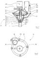
Bei der in Figur 9 gezeigten Ventil/Speichereinheit ist ein Servoventil 14 verwendet, welches in seinem strömungsmäßigen Aufbau weitgehend dem Servoventil nach Figur 7 entspricht. Die entsprechenden Ventilteile sind wieder mit denselben Bezugszeichen versehen.In the valve / storage unit shown in FIG. 9, a
An den horizontal ausgerichteten Einlaßstutzen 48 ist ein abgewinkeltes Zwischenstück 144 angesetzt, dessen in Figur 9 hinter der Zeichenebene liegender Einlaßstutzen 146 mit der von der Speischale herkommenden Leitung 12 verbunden wird. Ein zweiter, vertikal verlaufender Stutzen 148 des Zwischenstückes 144 nimmt einen unteren Verbindungsstutzen 150 auf, der an die schräggeneigte Bodenwand 152 eines insgesamt mit 154 bezeichneten Speicherbehälters angeformt ist.An angled
Die Bodenwand 152 hat eine Stufe 156, so daß die Bodenwand insgesamt der Außenkontur des Servoventiles 14 angepaßt ist.The
Der Speicherbehälter 154 hat rechteckig prismatischen Querschnitt, wobei ein oberer Behälterabschnitt eingezogen ist, wie bei 158 dargestellt. In dem so erhaltenen Rücksprung ist ein Schwimmerschalter 160 angeordnet, der über ein Rohr 162 mit dem Stutzen 148 verbunden ist.The
Der eingezogene Behälterabschnitt 158 hat selbst wieder rechteckig prismatischen Querschnitt und umgibt unter kleinem Abstand einen Schwimmer 164. Dieser trägt auf seiner Außenseite Noppen 166, über welche der Schwimmer 164 im Behälterabschnitt 158 leichtgängig geführt ist.The retracted
Der Schwimmer 164 hat eine mittige Bohrung 168, in welche ein Haltestab 170 eingeclipst ist. Der Haltestab 170 hat einen kreuzförmigen Stabendabschnitt 172, der in einer Öffnung 174 läuft, welche in der oberen Wand des Speicherbehälters vorgesehen ist. Radial vorstehende Nasen 176 begrenzen die Abwärtsbewegung des Haltestabes 170.The
Auf dem Stabendabschnitt 172 ist eine Dichtscheibe 178 angebracht, welche den unteren Rand der Öffnung 174 dicht verschließen kann, wenn der Schwimmer 164 entsprechend weit angehoben wird.On the
Bei normal arbeitendem Servoventil schaltet der Schwimmerschalter 160 so früh, daß die Dichtscheibe 178 noch nicht bis zum unteren Rand der Öffnung 174 angehoben worden ist. Arbeitet jedoch das Servoventil 14 oder der Schwimmerschalter 160 nicht korrekt, so steigt der Pegel des Abwassers im Inneren des Speicherbehälters 154 weiter an, der Schwimmer 164 wird angehoben, und die Dichtscheibe 178 verschließt die Öffnung 174. Damit kann kein weiteres Abwasser in den Speicherbehälter 154 fließen. Man erkennt das nicht korrekte Arbeiten der Ventil/Speicher-Einheit dann daran, daß Wasser sich bis in die Speischale zurückstaut. Ein Ausfließen von kontaminiertem Abwasser aus dem Speicherbehälter 154 erfolgt aber auch unter derartigen Störbedingungen nicht.With the servo valve operating normally, the
Wie aus Figur 9 und 10 ersichtlich, ist der Auslaßstutzen des Servoventiles 14 über einen Rohrwinkel 180 mit einem Einlaßstutzen 182 der in Figur 10 nur schematisch angedeuteten Amalgam-Abscheideeinheit 18 verbunden, die in der Regel eine Zentrifuge 184 umfaßt.As can be seen from FIGS. 9 and 10, the outlet connection of the
Bei dem in Figur 11 gezeigten Servoventil, welches strömungsmäßig demjenigen nach Figur 7 und nach Figur 9 entspricht, ist im Inneren des hohlen Ventilkörpers 44 ein insgesamt mit 186 bezeichneter Stützkörper vorgesehen, der an die Federsitzplatte 76 angeformt oder auf diese aufgesteckt ist.In the servo valve shown in FIG. 11, which corresponds in terms of flow to that according to FIG. 7 and according to FIG. 9, a support body, generally designated 186, is provided in the interior of the
Der Stützkörper 186 hat einen stabförmigen Endabschnitt 188, der in eine komplementäre Sackbohrung 190 des Bodens des Ventilkörpers 44 eingreift. Ein kegelstumpfförmiger Stützabschnitt 192 liegt unter Abstand parallel hinter der Innenfläche des Ventilkörpers 44 und trägt zwei in Umfangsrichtung verlaufende Stützrippen 194, 196, die in der Mitte zwischen den Lippen 130-3 und 130-4 bzw. 130-4 und 130-5 des Ventilkörpers 44 liegen. Auf diese Weise erhält man in dem größeren Radius aufweisenden Abschnitt des hohlen Steuerkopfes 70, in welchem der Steuerkopf weniger stabil ist, eine Verbesserung der Lippenabstützung in radialer Richtung. Da die Stützrippen 194, 196 zwischen diesen Lippen liegen, können letztere immer noch ausweichen, wenn sich zwischen ihnen und der Ventilsitzfläche ein größerer Amalgambrocken oder dergleichen befinden sollte.The
Bei einer abgewandelten Ventil/Speichereinheit, die in Figur 12 wiedergegeben ist, sind Bauteile, die obenstehend unter Bezugnahme auf Figur 9 schon in gleicher oder funktionsäquivalenter Form beschrieben wurden, wieder mit denselben Bezugszeichen versehen.In a modified valve / storage unit, which is shown in FIG. 12, components that have already been described above with reference to FIG. 9 in the same or functionally equivalent form are again provided with the same reference numerals.
Der Schwimmer 164 ist nun um eine horizontale Achse 198 verschwenkbar im Speicherbehälter 154 angeordnet. An den vorderen und hinteren Wänden des Speicherbehälters 154 angeformte, nach innen vorstehende Anschlagrippen 200 geben eine tiefste Stellung des Schwimmers 164 vor. Der Haltestab 170 ist fest auf dem Schwimmer 164 angebracht. Seine Stirnfläche dient gleichzeitig zur Betätigung des Stößels eines Mikroschalters 202, der in die Öffnung 174 hineinragt.The
Der Schwimmer 164 dient somit gleichzeitig zum Verschließen der Öffnung 174 durch die Dichtscheibe 178 und zum Betätigen des Mikroschalters 202, wenn der Pegel des im Speicherbehälter 154 akkumulierten Abwassers die Höhe H₁ erreicht.The
Wie aus Figur 12 ersichtlich, ist ein oberer Abschnitt des Speicherbehälters 154 als abnehmbarer Deckel 204 ausgebildet.As can be seen from FIG. 12, an upper section of the
Beim abgewandelten Ausführungsbeispiel nach Figur 13 sind Ventilteile, die vorstehend insbesondere bezugnehmend auf Figur 3 schon beschrieben wurden, mit denselben Bezugszeichen versehen. Der Ventilschaft 60 hat einen plattenförmigen Endabschnitt 206, der seitlich in vertikalen Führungsnuten 208 läuft, die auf der Innenseite des Führungsstutzens 90 vorgesehen sind. Im Endabschnitt 206 ist ein transversales Langloch 210 vorgesehen, in welchem ein Kurbelzapfen 212 Aufnahme findet. Dieser wird von der Abtriebswelle 214 eines elektrischen Getriebemotors 216 gedreht.In the modified exemplary embodiment according to FIG. 13, valve parts which have already been described above, in particular with reference to FIG. 3, have the same reference symbols Mistake. The valve stem 60 has a plate-shaped
Auf der Abtriebswelle 212 ist ein zweiarmiger Hebel 218 angeordnet, dessen Arme unter einem Winkel von 90° angestellt sind und als mit einer Reflexions-Lichtschrankeneinheit 220 zusammenarbeitende Stellungsgeberfahnen dienen. Einer der Arme trägt zugleich den Kurbelzapfen 212. Der Getriebemotor 216 wird in Öffnungsrichtung in Gang gesetzt, wenn ein ein Überschreiten des Maximalpegels H₁ anzeigendes Ausgangssignal des Druckfühlers 52 erhalten wird, und angehalten, wenn hiernach das erste Ausgangssignal der Lichtschrankeneinheit 220 vorliegt. Über den zwischen den Armen des Hebels 218 eingeschlossenen Winkel läßt sich der Öffnungshub des Ventilkörpers 44 vorgeben. Falls gewünscht, kann man diesen Hub auch durch reine Zeitsteuerung, z.B. eine monostabile Kippschaltung, vorgeben. In Schließrichtung des Ventilkörpers 44 wird der Getriebemotor 216 dann erregt, wenn der Druckfühler 52 ein dem unteren Flüssigkeitspegel H₂ zugeordnetes Signal bereitstellt. Die Schließbewegung wird mit dem ersten anschließend erhaltenen Ausgangssignal der Lichtschrankeneinheit 220 beendet.Arranged on the
Mit dem in den Figuren 13 und 14 gezeigten Servoventil erzielt man ein sehr zuverlässiges Öffnen und Schließen des Servoventiles bei nur geringem Leistungsaufwand. Der Kurbeltrieb dient nicht nur zur zusätzlichen Kraftübersetzung in der Nachbarschaft der Schließlage des Ventilkörpers 44, er erlaubt auch die Verwendung eines einfachen, keine hohe Präzision aufweisenden Stellungsgebers zur Steuerung des Getriebemotors 216.With the servo valve shown in FIGS. 13 and 14, a very reliable opening and closing of the servo valve is achieved with only a low expenditure of power. The crank mechanism not only serves for additional power transmission in the vicinity of the closed position of the
Claims (24)
- Cuspidor installation for a dental work-place, comprising a cuspidor (10) and a waste water line (12, 16) connected thereto, and comprising a servovalve (14) arranged in the waste water line (12, 16) and also a column height sensor (52; 160; 164, 202) arranged upstream of the servovalve (14) in the waste water line (12, 16), which column height sensor responds when the column of water upstream of the servovalve (14) reaches a specified value (H₁), in order then to activate the servovalve, characterised in that the servovalve (14) has a downwardly converging conical valve seat face (42) and the valve body (44) has a conical control face which is adapted to the contour of the valve seat face and which preferably has a plurality of successive, axially spaced lips (130-1 to 130-5) which cooperate with the valve seat face (42).
- Installation according to claim 1, characterised in that the column height sensor (52) is a pressure sensor which is in communication with the inlet of the housing (46) of the servovalve (14).
- Installation according to claim 1, characterised in that the column height sensor (52) has a level detector (160; 164, 202) arranged upstream of and spaced from the servovalve (14) in the waste water line (12, 16).
- Installation according to one of claims 1 to 3, characterised in that the servovalve (14) has a servomotor (72) that can be connected to a vacuum source (94) or to a source of compressed air.
- Installation according to claim 4 in conjunction with claim 3, characterised in that the pressure sensor (52) or level detector (160; 164, 202) is mechanically connected to a fluidics position indicator (100) by means of which the application of pressure to the servomotor (72) is controlled.
- Installation according to claim 5, characterised in that the pressure sensor (52) has a sensor piston (98) and the fluidics position indicator has a valve slide constructed on the piston shaft (100).
- Installation according to claim 6, characterised in that the valve slide (100) has an injector channel (110) which, in the working position of the pressure sensor (52), is flush with an intake funnel (112) and a working pipe (114) acted upon by a partial vacuum and, in that position, the small diameter end of the injection channel is in communication with a suction pipe (120) of the sensor housing (104), to which suction pipe there is connected the servomotor (72) of the servovalve (14), to which servomotor a partial vacuum can be applied.
- Installation according to one of claims 4 to 6, characterised in that a vacuum tapping channel (94) which leads into the outlet pipe (50) is provided in the valve housing (46).
- Installation according to claim 8, characterised in that the vacuum tapping channel (94) has an end portion (96) extending vertically downward in the outlet pipe (50).
- Installation according to one of claims 1 to 3, characterised in that the servovalve (14) has as the servomotor an electromagnet (132) which is energised in dependence upon the output signal of the column height sensor (52).
- Installation according to one of claims 1 to 3, characterised in that the servomotor is an electric motor (216), preferably an electric geared motor, and acts on the valve body (44) of the servovalve (14) via a crank drive (210, 212), and means (218, 220) are provided for stopping the electric motor (216) at the bottom dead centre position of the crank drive (210, 212) and in a raised position of the crank drive.
- Installation according to one of claims 1 to 11, characterised in that an actuating part (60) for the valve body (44) is guided (206, 208) in the valve housing (46, 19) so as to be displaceable along the axis of the valve seat.
- Installation according to one of claims 1 to 12, characterised in that the included angle of the valve seat face (42) is approximately 60°.
- Installation according to one of claims 1 to 13, characterised in that the axial dimension of the valve seat face (42) is from approximately 200 % to approximately 300 % of the diameter of the outlet channel (48).
- Installation according to one of claims 1 to 14, characterised in that the valve body (44) is a hollow, resilient injection-moulded part.
- Installation according to claim 15, characterised by a support body (186) which is arranged in the interior of the hollow valve body (44) and carries a plurality of support ribs (194, 196) extending in the circumferential direction.
- Installation according to claim 16, characterised in that the axial spacing of the support ribs (194, 196) corresponds to the axial spacing of the lips (130-1 to 130-5) of the valve body (44).
- Installation according to claim 16, characterised in that the support ribs (194, 196) are offset in the axial direction with respect to the lips (130-1 to 130-5) of the valve body (44), preferably by one half space.
- Installation according to one of claims 1 to 18, characterised in that the end of the valve body (44) remote from the valve seat face (42) carries a bellows (72, 72') which surrounds a spring (62) for biasing the valve body (46) and/or a valve-operating part (60) into the closed position.
- Installation according to claim 19 in conjunction with claim 4, characterised in that the bellows (72; 72') forms the servomotor which can be connected to a vacuum source (94).
- Installation according to one of claims 1 to 20, characterised in that the column height sensor (52; 160; 164, 202) additionally has an electrical contact (126; 202) which is operated when the specified water column height (H₁) is reached.
- Installation according to one of claims 1 to 20, characterised in that the inlet (48) of the servovalve (14) is connected to a storage vessel (154).
- Installation according to claim 22, characterised in that the storage vessel (154) has at its upper end a venting valve (174, 178) operated by a float (164).
- Installation according to claim 23, characterised in that the prismatic float (164) has bulbous projections (166) which run on a prismatic portion (158) of the storage vessel (154) surrounding the float (164) true to contour.
Priority Applications (1)
| Application Number | Priority Date | Filing Date | Title |
|---|---|---|---|
| AT90111808T ATE102464T1 (en) | 1989-06-24 | 1990-06-22 | CUTTERS INSTALLATION. |
Applications Claiming Priority (2)
| Application Number | Priority Date | Filing Date | Title |
|---|---|---|---|
| DE3920777 | 1989-06-24 | ||
| DE3920777A DE3920777A1 (en) | 1989-06-24 | 1989-06-24 | CUISINE INSTALLATION |
Publications (3)
| Publication Number | Publication Date |
|---|---|
| EP0406635A2 EP0406635A2 (en) | 1991-01-09 |
| EP0406635A3 EP0406635A3 (en) | 1991-04-10 |
| EP0406635B1 true EP0406635B1 (en) | 1994-03-09 |
Family
ID=6383524
Family Applications (1)
| Application Number | Title | Priority Date | Filing Date |
|---|---|---|---|
| EP90111808A Expired - Lifetime EP0406635B1 (en) | 1989-06-24 | 1990-06-22 | Dental cuspidor system |
Country Status (5)
| Country | Link |
|---|---|
| EP (1) | EP0406635B1 (en) |
| AT (1) | ATE102464T1 (en) |
| DD (1) | DD295755A5 (en) |
| DE (2) | DE3920777A1 (en) |
| ES (1) | ES2054156T3 (en) |
Families Citing this family (4)
| Publication number | Priority date | Publication date | Assignee | Title |
|---|---|---|---|---|
| DE9117064U1 (en) * | 1991-02-14 | 1995-07-06 | Sirona Dental Systems GmbH, 64625 Bensheim | Valve arrangement in a dental suction system |
| DE4243239A1 (en) * | 1992-12-19 | 1994-06-23 | Schwarz Joerg Martin Dr | Amalgam separation system |
| SE9404417L (en) * | 1994-12-20 | 1995-12-18 | Olle Olsson | Device for vacuum driven combined drain and point extraction system |
| DE19700118A1 (en) | 1997-01-03 | 1998-07-09 | Kaltenbach & Voigt | Method and device for emptying a collecting container for flowable excrement at a medical, in particular dental, treatment station |
Family Cites Families (5)
| Publication number | Priority date | Publication date | Assignee | Title |
|---|---|---|---|---|
| US3613131A (en) * | 1970-05-19 | 1971-10-19 | Dentsply Int Inc | Dental cuspidor |
| US4307475A (en) * | 1978-02-15 | 1981-12-29 | A-Dec, Inc. | Vacuum cuspidor |
| IT1187187B (en) * | 1985-07-31 | 1987-12-16 | Cattani Off Augusto & Co | SEPARATOR AND DISCHARGER OF LIQUIDS WITH DRAINAGE PUMP, IN PARTICULAR FOR DENTAL SUCTION PLANTS |
| DE8816512U1 (en) * | 1988-08-10 | 1989-09-28 | Siemens AG, 1000 Berlin und 8000 München | Dental suction device with means for controlling suction power |
| DE8904379U1 (en) * | 1989-04-07 | 1989-08-03 | Siemens AG, 1000 Berlin und 8000 München | Dental suction device containing several wastewater sources |
-
1989
- 1989-06-24 DE DE3920777A patent/DE3920777A1/en not_active Ceased
-
1990
- 1990-06-22 EP EP90111808A patent/EP0406635B1/en not_active Expired - Lifetime
- 1990-06-22 ES ES90111808T patent/ES2054156T3/en not_active Expired - Lifetime
- 1990-06-22 DE DE90111808T patent/DE59004868D1/en not_active Expired - Lifetime
- 1990-06-22 AT AT90111808T patent/ATE102464T1/en not_active IP Right Cessation
- 1990-06-22 DD DD90341975A patent/DD295755A5/en not_active IP Right Cessation
Also Published As
| Publication number | Publication date |
|---|---|
| EP0406635A3 (en) | 1991-04-10 |
| ES2054156T3 (en) | 1994-08-01 |
| DE3920777A1 (en) | 1991-01-10 |
| DD295755A5 (en) | 1991-11-14 |
| ATE102464T1 (en) | 1994-03-15 |
| DE59004868D1 (en) | 1994-04-14 |
| EP0406635A2 (en) | 1991-01-09 |
Similar Documents
| Publication | Publication Date | Title |
|---|---|---|
| DE2713321C2 (en) | Method and device for separating liquid and solid components from the suction media mixture coming from the mouth of a patient | |
| DE2929804C2 (en) | Dental suction device | |
| DE9007491U1 (en) | Device for draining condensate from pressure systems or similar. | |
| DE2005567C2 (en) | Valve arrangement in a suction line of a suction system for dental purposes | |
| DE69932063T2 (en) | IMPROVED AUTOMATIC EXHAUST VALVE | |
| EP3314063A1 (en) | Pneumatic control for a vacuum toilet | |
| EP0406635B1 (en) | Dental cuspidor system | |
| EP0332090B1 (en) | Apparatus for extracting and removing a liquid containing noxious material, especially of dirty water | |
| DE2010111A1 (en) | Water closet with ventilation and flushing device | |
| EP2746474B1 (en) | Flushing device with odour extractor | |
| WO1983000260A1 (en) | Installation for automatically filling battery cells | |
| DE2065735B2 (en) | Inlet valve for vacuum drain lines | |
| EP0239892B1 (en) | Method and device for operating a vacuum sewer plant | |
| DE102004047994A1 (en) | Pipe ventilation arrangement for a drain line in a water-conducting household appliance | |
| EP2447429A1 (en) | Antiflooding valve | |
| EP0195389B1 (en) | Tube disconnector | |
| DE3321752A1 (en) | DISHWASHER FOR BUCKET MILLING PLANTS | |
| EP0852129B1 (en) | Method and device for emptying a collecting container for fluid waste in a medical, in particular dental treatment station | |
| EP0503209B1 (en) | Regulating device for changing the cross section of the discharge opening of an equalizing reservoir, especially a rain water storage basin | |
| EP0216101B1 (en) | Pneumatic control device for a shut-off valve of a vacuum waste water conduit | |
| DE8519327U1 (en) | Suction bottle, especially for sucking secretions from wound cavities | |
| EP0183155B1 (en) | Automatic liquid-raising device | |
| EP0937830A2 (en) | Vacuum or low-pressure suction system | |
| DE4121932A1 (en) | Dental treatment waste water separator - has servo valve opening control to prevent build=up on intermediate store wall | |
| DE1110577B (en) | Suction truck with overfill prevention device |
Legal Events
| Date | Code | Title | Description |
|---|---|---|---|
| PUAI | Public reference made under article 153(3) epc to a published international application that has entered the european phase |
Free format text: ORIGINAL CODE: 0009012 |
|
| AK | Designated contracting states |
Kind code of ref document: A2 Designated state(s): AT CH DE ES FR GB IT LI SE |
|
| PUAL | Search report despatched |
Free format text: ORIGINAL CODE: 0009013 |
|
| AK | Designated contracting states |
Kind code of ref document: A3 Designated state(s): AT CH DE ES FR GB IT LI SE |
|
| 17P | Request for examination filed |
Effective date: 19910912 |
|
| 17Q | First examination report despatched |
Effective date: 19921210 |
|
| GRAA | (expected) grant |
Free format text: ORIGINAL CODE: 0009210 |
|
| AK | Designated contracting states |
Kind code of ref document: B1 Designated state(s): AT CH DE ES FR GB IT LI SE |
|
| REF | Corresponds to: |
Ref document number: 102464 Country of ref document: AT Date of ref document: 19940315 Kind code of ref document: T |
|
| REF | Corresponds to: |
Ref document number: 59004868 Country of ref document: DE Date of ref document: 19940414 |
|
| ITF | It: translation for a ep patent filed | ||
| GBT | Gb: translation of ep patent filed (gb section 77(6)(a)/1977) |
Effective date: 19940608 |
|
| ET | Fr: translation filed | ||
| REG | Reference to a national code |
Ref country code: ES Ref legal event code: FG2A Ref document number: 2054156 Country of ref document: ES Kind code of ref document: T3 |
|
| PLBI | Opposition filed |
Free format text: ORIGINAL CODE: 0009260 |
|
| EAL | Se: european patent in force in sweden |
Ref document number: 90111808.3 |
|
| 26 | Opposition filed |
Opponent name: TRAWOEGER WERNER Effective date: 19941204 |
|
| PLBO | Opposition rejected |
Free format text: ORIGINAL CODE: EPIDOS REJO |
|
| PLBN | Opposition rejected |
Free format text: ORIGINAL CODE: 0009273 |
|
| STAA | Information on the status of an ep patent application or granted ep patent |
Free format text: STATUS: OPPOSITION REJECTED |
|
| 27O | Opposition rejected |
Effective date: 19951224 |
|
| EUG | Se: european patent has lapsed | ||
| REG | Reference to a national code |
Ref country code: GB Ref legal event code: IF02 |
|
| PGFP | Annual fee paid to national office [announced via postgrant information from national office to epo] |
Ref country code: ES Payment date: 20060613 Year of fee payment: 17 |
|
| PGFP | Annual fee paid to national office [announced via postgrant information from national office to epo] |
Ref country code: AT Payment date: 20060626 Year of fee payment: 17 Ref country code: CH Payment date: 20060626 Year of fee payment: 17 Ref country code: FR Payment date: 20060626 Year of fee payment: 17 Ref country code: GB Payment date: 20060626 Year of fee payment: 17 |
|
| PGFP | Annual fee paid to national office [announced via postgrant information from national office to epo] |
Ref country code: SE Payment date: 20060627 Year of fee payment: 17 |
|
| REG | Reference to a national code |
Ref country code: CH Ref legal event code: PL |
|
| EUG | Se: european patent has lapsed | ||
| GBPC | Gb: european patent ceased through non-payment of renewal fee |
Effective date: 20070622 |
|
| PG25 | Lapsed in a contracting state [announced via postgrant information from national office to epo] |
Ref country code: AT Free format text: LAPSE BECAUSE OF NON-PAYMENT OF DUE FEES Effective date: 20070622 |
|
| REG | Reference to a national code |
Ref country code: FR Ref legal event code: ST Effective date: 20080229 |
|
| PG25 | Lapsed in a contracting state [announced via postgrant information from national office to epo] |
Ref country code: LI Free format text: LAPSE BECAUSE OF NON-PAYMENT OF DUE FEES Effective date: 20070630 Ref country code: CH Free format text: LAPSE BECAUSE OF NON-PAYMENT OF DUE FEES Effective date: 20070630 |
|
| PG25 | Lapsed in a contracting state [announced via postgrant information from national office to epo] |
Ref country code: GB Free format text: LAPSE BECAUSE OF NON-PAYMENT OF DUE FEES Effective date: 20070622 |
|
| PG25 | Lapsed in a contracting state [announced via postgrant information from national office to epo] |
Ref country code: SE Free format text: LAPSE BECAUSE OF NON-PAYMENT OF DUE FEES Effective date: 20070623 |
|
| REG | Reference to a national code |
Ref country code: ES Ref legal event code: FD2A Effective date: 20070623 |
|
| PG25 | Lapsed in a contracting state [announced via postgrant information from national office to epo] |
Ref country code: FR Free format text: LAPSE BECAUSE OF NON-PAYMENT OF DUE FEES Effective date: 20070702 |
|
| PG25 | Lapsed in a contracting state [announced via postgrant information from national office to epo] |
Ref country code: ES Free format text: LAPSE BECAUSE OF NON-PAYMENT OF DUE FEES Effective date: 20070623 |
|
| PGFP | Annual fee paid to national office [announced via postgrant information from national office to epo] |
Ref country code: IT Payment date: 20090625 Year of fee payment: 20 |
|
| PGFP | Annual fee paid to national office [announced via postgrant information from national office to epo] |
Ref country code: DE Payment date: 20090831 Year of fee payment: 20 |
|
| PG25 | Lapsed in a contracting state [announced via postgrant information from national office to epo] |
Ref country code: DE Free format text: LAPSE BECAUSE OF EXPIRATION OF PROTECTION Effective date: 20100622 |