EP0406486A1 - Control system for controlling consumer apparatus, in particular audio and/or video apparatus and consumer apparatus for use in such control system - Google Patents
Control system for controlling consumer apparatus, in particular audio and/or video apparatus and consumer apparatus for use in such control system Download PDFInfo
- Publication number
- EP0406486A1 EP0406486A1 EP89201789A EP89201789A EP0406486A1 EP 0406486 A1 EP0406486 A1 EP 0406486A1 EP 89201789 A EP89201789 A EP 89201789A EP 89201789 A EP89201789 A EP 89201789A EP 0406486 A1 EP0406486 A1 EP 0406486A1
- Authority
- EP
- European Patent Office
- Prior art keywords
- command
- commands
- group
- control system
- address range
- Prior art date
- Legal status (The legal status is an assumption and is not a legal conclusion. Google has not performed a legal analysis and makes no representation as to the accuracy of the status listed.)
- Granted
Links
Images
Classifications
-
- H—ELECTRICITY
- H04—ELECTRIC COMMUNICATION TECHNIQUE
- H04B—TRANSMISSION
- H04B1/00—Details of transmission systems, not covered by a single one of groups H04B3/00 - H04B13/00; Details of transmission systems not characterised by the medium used for transmission
- H04B1/06—Receivers
- H04B1/16—Circuits
- H04B1/20—Circuits for coupling gramophone pick-up, recorder output, or microphone to receiver
- H04B1/205—Circuits for coupling gramophone pick-up, recorder output, or microphone to receiver with control bus for exchanging commands between units
-
- G—PHYSICS
- G11—INFORMATION STORAGE
- G11B—INFORMATION STORAGE BASED ON RELATIVE MOVEMENT BETWEEN RECORD CARRIER AND TRANSDUCER
- G11B20/00—Signal processing not specific to the method of recording or reproducing; Circuits therefor
- G11B20/02—Analogue recording or reproducing
-
- G—PHYSICS
- G08—SIGNALLING
- G08C—TRANSMISSION SYSTEMS FOR MEASURED VALUES, CONTROL OR SIMILAR SIGNALS
- G08C19/00—Electric signal transmission systems
- G08C19/16—Electric signal transmission systems in which transmission is by pulses
- G08C19/28—Electric signal transmission systems in which transmission is by pulses using pulse code
Definitions
- the invention relates to a control system for controlling consumer apparatus, in particular audio and/or video apparatus.
- Various such apparatus have been in general use, the control signals nowadays have been formatted as a bit stream, for in that bit stream specifying a qualitative operation mode and/or quantitative operation settings.
- the invention thereto provides a control system for controlling distributed consumer apparatus, said system having a command generating means for generating a command item for an apparatus in said system, said command item being structured as a string of an operation code followed by a set of command operand codes, for under control of said operation code accessing a local command table of an apparatus so addressed, said local command table containing a first address range for storing general commands, and a second address range for function group commands.
- the invention also relates to a consumer apparatus for use in such a system and comprising receiving means is provided for transporting any said command item between said command generating means and any apparatus so addressed.
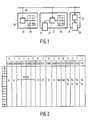
- Figure 1 is a block diagram of an elementary system according to the invention. It has three apparatuses 20, 22, 24 and by way of example is projected on a audio system. Likewise it may be video, mixed audio-video or comprise other consumer functions such as lighting/environment control, food preparation or other.
- Block 20 is a controller-only block. It has a keyboard with 12 keys as shown; the keycode conventionally may be translated to a control byte in translator 28 that also comprises an interface to serial bus 30, to which block 20 functions as a master station.
- the bus definition may be according to the D2B format as specified in US patent 4,429,384 to the same assignee.
- Block 24 may, by means of subsystem 38 render the consumer function, such as operating as a tuner, turntable, recorder, or other.
- Block 24 receives from the serial bus 30 formatted operation codes and/or command operand codes, and/or data items and/or request codes. These each translate to information that is specific to apparatus block 24, preferably by translating in element 36, which thereto functions as bus interface cum command table to be specified infra. With respect to serial bus 30, block 24 in general would function as a slave station that would react to block 20's control signals.
- Block 22 has both user function block 32 and keyboard 40.
- Element 34 functions as bus interface, comprises the command table and may with respect to bus 20 operate either as master or as slave. In principle, the system can operate in various configurations, for example as follows:
- the above system is given merely by way of example.
- the apparatuses may be different or more numerous, interaction patterns may be more complex, keyboards may be replaced by function-assigned key sets, the system as a whole may operate as a subordinate system to a higher level system, and many other variations would not render it incommensurate to the present invention.
- Figure 2 is a diagram of a command table.
- the table may be defined as read-only memory, as a random-access read-write memory, as a combination of the two or be embodied in a software program.
- the table For accessing the table, first the apparatus is addressed, for example in that a prospective master station grabs the bus and produces a message directed to the intended slave station.
- the table comprises 1k-(1024) entries of 1 byte each. Addressing by a most significant nibble of an address byte, shown at the top (1..F) and by a least significant nibble of an address byte, shown at left (1..F). Conventionally, nibbles have four bits.
- the table from left to right comprises the following columns 0,1: reserved; 2-5: ASCII character codes or controlling values or Alias; 6-7: standard operand values; 8-9: reserved; 10-11: general commands; C-D: functional group commands; E-F: function specific commands. Within each column, sixteen locations are available.
- operands OCR
- OPC operation codes
- a command consists of an operation code (OPC) and a set of operand codes (OPR).
- An OPC has a length of one byte, and is followed by zero or one or more OPR bytes.
- the operand specifies the operation which is indicated by the operation code.
- the operand can be: either one out of 32 dedicated (standard) operands; - ASCII value - controlling value.
- the OPR codes are defined as follows:
- 1 ⁇ .. ⁇ n means a sequence of one or more items as recited between the parentheses.
- the vertical stroke means -or-, either one of the possibilities materializing.
- the data-commands fulfill the rules as specified for the command sequence and specify the context of the following data.
- -'H- indicates a hexadecimal notation.
- a command is a combination of an OPC and 1 or more OPR codes.
- the OPC is to be used as delimiter between 2 commands.
- the Commands are ordered in 3 groups:
- the commands are defined as follows: SA′, DA′, SSDA and DSDA are using all 8 bits of the byte.
- a gateway-name indicates an in-bus interface that interconnects two buses having the same or different protocol specifications.
- -begin 1- indicates that the bus protocol at the -far-side of the interface either conforms to IHS Eureka or to the Japanese Home bus.
- the associated bus protocols have not been repeated here.
- -begin-2- is intended for within an apparatus specifying a subdevice, such as tuner function in a video cassette recorder.
- avc indicates audio-video control
- CT means communication/telecom
- HK means house keeping
- SCC System Common Command.
- the System Control Commands, CT-TABLE-SELECTOR, HK-TABLE-SELECTOR and avc-table selector each select one of the group-function or specific-function commands, one table selector for each service. In case no table selector is specified, the default table for that type of destination device is used. Each apparatus has a default table for its specific apparatus category.
- Group Function commands Specific Function commands type of destination (sub)device video commands video monitor video commands video effector video commands camera commands video camera audio commands audio amplifier audio commands audio effector deck/player commands video tape recorder deck/player commands video disk player deck/player commands audio tape recorder deck/player commands audio disk player tuner commands video tuner commands video tuning system tuner commands audio tuner commands audio tuner text function commands teletext decoder text function commands videotext decoder timer commands timer User I/O commands User I/O Connection commands Connection commands Switch Box Each command, not belonging to the default table, must be specified by the table selector.
- the table selected by the avc-table-selector command is effective only for the immediately following command, data or request. After execution of that following command, data or request, the default table is effective again.
- a deck device by default would be executing deck commands. Under control of the above selector command it would execute one command received, for example, as a video command, such as a -crisp- control command. This selecting for one command only allows for restricting the necessary RAM capacity.
- the command extension specifies an other meaning of the next command.
- the command extension is valid for the following command or request.
- a syntax rule for the data bytes depends on the application in the receiving consumer apparatus and can be defined for each application independently. When a certain syntax is used, that syntax is specified by commands in the command-data-message.
- All Static and Dynamic properties and characteristics are modeled in the property memory of a (sub)device.
- a property memory may comprise the identity of the device (such as brand, type, version, serial no.) and the status of the device (stand by, etc.) and may be a virtual memory.
- Each Audio/Video device shall be implemented with a property memory. Any device can have access to the property memory of a device using the request message.
- the request is terminated with the termination code "1D" to indicate that the request is completed, the slave has all information to prepare the answer.
- the syntax for requests is:
- the request-code is in the range '20'H to 'FF'H.
- the value of the request-arguments are in the range '20'H to '7F'H.
- the requests are grouped to the following divisions:
- General requests General requests for a (sub)device, like request for the identity (brand name, type number) and general requests for status of a (sub)device. Requests are valid for all types of (sub)devices. Group requests: Static and Dynamic requests, valid for a group of (sub)devices. Specific Function requests: Static and Dynamic requests, valid for one specific function.
- Dynamic Requests related to the general commands, valid for all types of (sub)devices.
- Group requests Dynamic requests, related to the group function commands, valid for a group of (sub)devices.
- Specific Function requests Dynamic requests, related to the specific function commands, valid for one specific function.
- a request can be addressed to a device or sub device (using Begin 2).
- a service Classification Command can be used to select an other table for a request.
- the answers must be read by the master using the 'read data' control code.
- a request related to a command has an operation code, which is related to the operation code of the command. It is of further great advantage that a response to a request related to a command has an operand code, which is related to the operand code of said command.
- the expression "related" is including -identity-, which means that the same operation code and operand code(s) are used for the command and the command oriented request. Whether a request or a command is sent is determined by the control bit, which is sent in advance of the command or request.
Abstract
Description
- The invention relates to a control system for controlling consumer apparatus, in particular audio and/or video apparatus. Various such apparatus have been in general use, the control signals nowadays have been formatted as a bit stream, for in that bit stream specifying a qualitative operation mode and/or quantitative operation settings.
- A control system of the kind described has been described in JP Application 64-60572, corresponding US Application Serial No. 286.575 to the same assignee (PHN 12.484), herein incorporated by reference. The general trend in comsumer service systems is to integrate an arbitrary selection of such apparatus to function collectively. The interaction may be on a control level in that a first apparatus only controls the function of a second apparatus. Alternatively, also the user function is fulfilled by the combination, for example in that one apparatus is a broadcast tuner for receiving a particular signal and a second apparatus is a recorder for the signal so received. In general, the various apparatuses in the system may be of various different types, even when fulfilling the same function, and also of various manufacturers. Thus, in principle each aparatus could require its own particular mode/operation settings that could be expressly non-standard.
- Among other things, it is an object of the present invention to relieve any control command generating entity outside any apparatus so controlled from the need to expressly specify operation mode and/or operation settings for the latter apparatus. According to one of its aspects, the invention thereto provides a control system for controlling distributed consumer apparatus, said system having a command generating means for generating a command item for an apparatus in said system, said command item being structured as a string of an operation code followed by a set of command operand codes, for under control of said operation code accessing a local command table of an apparatus so addressed, said local command table containing a first address range for storing general commands, and a second address range for function group commands.
- The invention also relates to a consumer apparatus for use in such a system and comprising receiving means is provided for transporting any said command item between said command generating means and any apparatus so addressed.
- Various advantageous aspects are recited in dependent Claims.
- The invention will in particular be further explained with respect to accompanying Figures that show preferred realizations.
- Figure 1 is a block diagram of an elementary system according to the invention;
- Figure 2 is a diagram of a command table.
- Figure 1 is a block diagram of an elementary system according to the invention. It has three
apparatuses Block 20 is a controller-only block. It has a keyboard with 12 keys as shown; the keycode conventionally may be translated to a control byte intranslator 28 that also comprises an interface toserial bus 30, to which block 20 functions as a master station. The bus definition may be according to the D²B format as specified in US patent 4,429,384 to the same assignee.Block 24 may, by means ofsubsystem 38 render the consumer function, such as operating as a tuner, turntable, recorder, or other. Of course, two different blocks could cooperate with respect to their consumer function, in that a first block would be a tuner, a second block a recorder or loudspeaker system. Other, and more complicated situations have been omitted for clarity. For this cooperation, the associated apparatuses will often exchange data, such as digitized audio, along high-speed links not shown.Block 24 receives from theserial bus 30 formatted operation codes and/or command operand codes, and/or data items and/or request codes. These each translate to information that is specific toapparatus block 24, preferably by translating inelement 36, which thereto functions as bus interface cum command table to be specified infra. With respect toserial bus 30,block 24 in general would function as a slave station that would react to block 20's control signals. -
Block 22 has bothuser function block 32 andkeyboard 40.Element 34 functions as bus interface, comprises the command table and may with respect tobus 20 operate either as master or as slave. In principle, the system can operate in various configurations, for example as follows: - 1. block 22 functions independently under local control
- 2.
block 20controls block 24 - 3.
block 22controls block 24 - 4.
block 20 controls bothblocks - 5.
block 22 controls bothblocks - The above system is given merely by way of example. The apparatuses may be different or more numerous, interaction patterns may be more complex, keyboards may be replaced by function-assigned key sets, the system as a whole may operate as a subordinate system to a higher level system, and many other variations would not render it incommensurate to the present invention.
- Figure 2 is a diagram of a command table. The table may be defined as read-only memory, as a random-access read-write memory, as a combination of the two or be embodied in a software program. For accessing the table, first the apparatus is addressed, for example in that a prospective master station grabs the bus and produces a message directed to the intended slave station. Now, as shown, the table comprises 1k-(1024) entries of 1 byte each. Addressing by a most significant nibble of an address byte, shown at the top (1..F) and by a least significant nibble of an address byte, shown at left (1..F). Conventionally, nibbles have four bits. The table from left to right comprises the
following columns 0,1: reserved; 2-5: ASCII character codes or controlling values or Alias; 6-7: standard operand values; 8-9: reserved; 10-11: general commands; C-D: functional group commands; E-F: function specific commands. Within each column, sixteen locations are available. Generally, operands (OPR) fill the left half of the table, operation codes (OPC) fill the right half of the table.
Now, a command consists of an operation code (OPC) and a set of operand codes (OPR). An OPC has a length of one byte, and is followed by zero or one or more OPR bytes. The operand specifies the operation which is indicated by the operation code.
The operand can be:
either one out of 32 dedicated (standard) operands;
- ASCII value
- controlling value. - The OPR codes are defined as follows:

- The syntax of an application message is as follows:Herein, 1{..}n means a sequence of one or more items as recited between the parentheses.
 Herein, the vertical stroke means -or-, either one of the possibilities materializing.
 The data-commands fulfill the rules as specified for the command sequence and specify the context of the following data.
 Herein, -'H- indicates a hexadecimal notation.
 A command is a combination of an OPC and 1 or more OPR codes. The OPC is to be used as delimiter between 2 commands. The Commands are ordered in 3 groups:
- General commands with same meaning for all functions.
- Group Function commands with same meaning for a group of functions.
- Specific Function commands with valid meaning for the specified function.
- The commands are defined as follows:SA′, DA′, SSDA and DSDA are using all 8 bits of the byte.

- Herein a gateway-name indicates an in-bus interface that interconnects two buses having the same or different protocol specifications. In particular, -begin 1- indicates that the bus protocol at the -far-side of the interface either conforms to IHS Eureka or to the Japanese Home bus. For brevity, the associated bus protocols have not been repeated here.
-begin-2- is intended for within an apparatus specifying a subdevice, such as tuner function in a video cassette recorder.
- In the above, avc indicates audio-video control, CT means communication/telecom, HK means house keeping, SCC means System Common Command. Capital letters indicate that for brevity no further specification has been given, small letters indicate that such specification is to follow. Now, the System Control Commands, CT-TABLE-SELECTOR, HK-TABLE-SELECTOR and avc-table selector each select one of the group-function or specific-function commands, one table selector for each service. In case no table selector is specified, the default table for that type of destination device is used. Each apparatus has a default table for its specific apparatus category.
Group Function commands Specific Function commands type of destination (sub)device video commands video monitor video commands video effector video commands camera commands video camera audio commands audio amplifier audio commands audio effector deck/player commands video tape recorder deck/player commands video disk player deck/player commands audio tape recorder deck/player commands audio disk player tuner commands video tuner commands video tuning system tuner commands audio tuner commands audio tuner text function commands teletext decoder text function commands videotext decoder timer commands timer User I/O commands User I/O Connection commands Connection commands Switch Box - The table selected by the avc-table-selector command is effective only for the immediately following command, data or request. After execution of that following command, data or request, the default table is effective again. For example, a deck device by default would be executing deck commands. Under control of the above selector command it would execute one command received, for example, as a video command, such as a -crisp- control command. This selecting for one command only allows for restricting the necessary RAM capacity.

- The command extension, followed by OPR, specifies an other meaning of the next command. The command extension is valid for the following command or request.


- Bytes to be sent as data are transparant bytes. How to use or interprete this data is specified within the context of the data. This can be done by preceding commands.

- A syntax rule for the data bytes depends on the application in the receiving consumer apparatus and can be defined for each application independently. When a certain syntax is used, that syntax is specified by commands in the command-data-message.
- All Static and Dynamic properties and characteristics are modeled in the property memory of a (sub)device. Such a property memory may comprise the identity of the device (such as brand, type, version, serial no.) and the status of the device (stand by, etc.) and may be a virtual memory. Each Audio/Video device shall be implemented with a property memory. Any device can have access to the property memory of a device using the request message.

- The request is terminated with the termination code "1D" to indicate that the request is completed, the slave has all information to prepare the answer. The syntax for requests is:

- The request-code is in the range '20'H to 'FF'H. The value of the request-arguments are in the range '20'H to '7F'H. The requests are grouped to the following divisions:
- General requests:
General requests for a (sub)device, like request for the identity (brand name, type number) and general requests for status of a (sub)device. Requests are valid for all types of (sub)devices.
Group requests:
Static and Dynamic requests, valid for a group of (sub)devices.
Specific Function requests:
Static and Dynamic requests, valid for one specific function. - General command oriented requests:
Dynamic Requests, related to the general commands, valid for all types of (sub)devices.
Group requests:
Dynamic requests, related to the group function commands, valid for a group of (sub)devices.
Specific Function requests:
Dynamic requests, related to the specific function commands, valid for one specific function.
A request can be addressed to a device or sub device (using Begin 2). A service Classification Command can be used to select an other table for a request.


- The answers must be read by the master using the 'read data' control code.
The syntax for the answers (properties) is:The property values are in the range '20'H to 'FF'H.
<terminator> ::= '1D'H - It is of great advantage that a request related to a command has an operation code, which is related to the operation code of the command. It is of further great advantage that a response to a request related to a command has an operand code, which is related to the operand code of said command. In the foregoing the expression "related" is including -identity-, which means that the same operation code and operand code(s) are used for the command and the command oriented request. Whether a request or a command is sent is determined by the control bit, which is sent in advance of the command or request.
Claims (27)
Priority Applications (8)
| Application Number | Priority Date | Filing Date | Title |
|---|---|---|---|
| DE68927407T DE68927407T2 (en) | 1989-07-06 | 1989-07-06 | Control system for controlling consumer devices, in particular audio and / or video devices, and consumer device for use in such a control system |
| ES89201789T ES2095835T3 (en) | 1989-07-06 | 1989-07-06 | CONTROL SYSTEM FOR CONTROLLING CONSUMER DEVICES, PARTICULARLY AUDIO AND / OR VIDEO DEVICES AND CONSUMER DEVICES FOR USE IN A CONTROL SYSTEM OF THIS TYPE. |
| EP89201789A EP0406486B1 (en) | 1989-07-06 | 1989-07-06 | Control system for controlling consumer apparatus, in particular audio and/or video apparatus and consumer apparatus for use in such control system |
| AT89201789T ATE144853T1 (en) | 1989-07-06 | 1989-07-06 | CONTROL SYSTEM FOR CONTROLLING CONSUMER DEVICES, IN PARTICULAR AUDIO AND/OR VIDEO DEVICES, AND CONSUMER DEVICE FOR USE IN SUCH A CONTROL SYSTEM |
| JP1336834A JP3015917B2 (en) | 1989-07-06 | 1989-12-27 | Control system for consumer devices |
| FI903346A FI107761B (en) | 1989-07-06 | 1990-07-03 | Control system for controlling a consumer device, in particular an audio and / or video device, and a consumer device useful in such a control system |
| KR1019900010046A KR100191110B1 (en) | 1989-07-06 | 1990-07-04 | Control system for controlling consumer apparatus, in particular audio and/or video apparatus and consumer apparatus |
| US08/416,944 US5650775A (en) | 1989-07-06 | 1995-04-04 | Control system for controlling consumer apparatus |
Applications Claiming Priority (1)
| Application Number | Priority Date | Filing Date | Title |
|---|---|---|---|
| EP89201789A EP0406486B1 (en) | 1989-07-06 | 1989-07-06 | Control system for controlling consumer apparatus, in particular audio and/or video apparatus and consumer apparatus for use in such control system |
Publications (2)
| Publication Number | Publication Date |
|---|---|
| EP0406486A1 true EP0406486A1 (en) | 1991-01-09 |
| EP0406486B1 EP0406486B1 (en) | 1996-10-30 |
Family
ID=8202429
Family Applications (1)
| Application Number | Title | Priority Date | Filing Date |
|---|---|---|---|
| EP89201789A Expired - Lifetime EP0406486B1 (en) | 1989-07-06 | 1989-07-06 | Control system for controlling consumer apparatus, in particular audio and/or video apparatus and consumer apparatus for use in such control system |
Country Status (7)
| Country | Link |
|---|---|
| EP (1) | EP0406486B1 (en) |
| JP (1) | JP3015917B2 (en) |
| KR (1) | KR100191110B1 (en) |
| AT (1) | ATE144853T1 (en) |
| DE (1) | DE68927407T2 (en) |
| ES (1) | ES2095835T3 (en) |
| FI (1) | FI107761B (en) |
Cited By (9)
| Publication number | Priority date | Publication date | Assignee | Title |
|---|---|---|---|---|
| EP0893896A2 (en) * | 1997-06-12 | 1999-01-27 | Yazaki Corporation | Information network system |
| WO1999055070A2 (en) * | 1998-04-22 | 1999-10-28 | Koninklijke Philips Electronics N.V. | Management of functionality in a consumer electronics system |
| WO1999055071A2 (en) * | 1998-04-22 | 1999-10-28 | Koninklijke Philips Electronics N.V. | Management of functionality in a consumer electronics system |
| WO1999056242A2 (en) * | 1998-04-23 | 1999-11-04 | Koninklijke Philips Electronics N.V. | A software controlled imaging system with user interface controller module |
| US6071422A (en) * | 1995-04-18 | 2000-06-06 | Cobe Laboratories, Inc. | Particle separation method and apparatus |
| US6131124A (en) * | 1997-02-24 | 2000-10-10 | Yazaki Corporation | Data communication method and data communication system using this method |
| US6732282B1 (en) * | 2000-10-20 | 2004-05-04 | Sony Corporation | System and method of determining the power relationship among devices |
| US6747982B2 (en) | 1997-02-21 | 2004-06-08 | Yazaki Corporation | Communication method, communication system, and gate way used in the communication system |
| EP3089026A1 (en) * | 2000-05-03 | 2016-11-02 | Nokia Technologies Oy | Method for controlling a system, in particular an electrical and/or electronic system with at least one application device |
Families Citing this family (1)
| Publication number | Priority date | Publication date | Assignee | Title |
|---|---|---|---|---|
| GB2427733A (en) * | 2005-06-29 | 2007-01-03 | Symbian Software Ltd | Remote control |
Citations (1)
| Publication number | Priority date | Publication date | Assignee | Title |
|---|---|---|---|---|
| EP0186872A2 (en) * | 1984-12-31 | 1986-07-09 | Wang Laboratories Inc. | Terminal protocols |
Family Cites Families (1)
| Publication number | Priority date | Publication date | Assignee | Title |
|---|---|---|---|---|
| NL8800639A (en) * | 1988-03-16 | 1989-10-16 | Philips Nv | ONE-CHANNEL COMMUNICATION BUS SYSTEM AND STATION FOR USE IN SUCH A COMMUNICATION BUS SYSTEM. |
-
1989
- 1989-07-06 ES ES89201789T patent/ES2095835T3/en not_active Expired - Lifetime
- 1989-07-06 AT AT89201789T patent/ATE144853T1/en not_active IP Right Cessation
- 1989-07-06 DE DE68927407T patent/DE68927407T2/en not_active Expired - Fee Related
- 1989-07-06 EP EP89201789A patent/EP0406486B1/en not_active Expired - Lifetime
- 1989-12-27 JP JP1336834A patent/JP3015917B2/en not_active Expired - Fee Related
-
1990
- 1990-07-03 FI FI903346A patent/FI107761B/en active IP Right Grant
- 1990-07-04 KR KR1019900010046A patent/KR100191110B1/en not_active IP Right Cessation
Patent Citations (1)
| Publication number | Priority date | Publication date | Assignee | Title |
|---|---|---|---|---|
| EP0186872A2 (en) * | 1984-12-31 | 1986-07-09 | Wang Laboratories Inc. | Terminal protocols |
Non-Patent Citations (1)
| Title |
|---|
| PROCEEDINGS OF THE INTERNATIONAL CONGRESS ON TRANSPORTATION ELECTRONICS, October 20-22 1986, pages 85-97, Publisher: SAE, Warrendale (US) HIROSHI TAJIMA et al "A Distributed Architecture Car Audio System" * |
Cited By (17)
| Publication number | Priority date | Publication date | Assignee | Title |
|---|---|---|---|---|
| US6071422A (en) * | 1995-04-18 | 2000-06-06 | Cobe Laboratories, Inc. | Particle separation method and apparatus |
| US6747982B2 (en) | 1997-02-21 | 2004-06-08 | Yazaki Corporation | Communication method, communication system, and gate way used in the communication system |
| US6131124A (en) * | 1997-02-24 | 2000-10-10 | Yazaki Corporation | Data communication method and data communication system using this method |
| EP0893896A3 (en) * | 1997-06-12 | 1999-04-14 | Yazaki Corporation | Information network system |
| EP0893896A2 (en) * | 1997-06-12 | 1999-01-27 | Yazaki Corporation | Information network system |
| US6754719B1 (en) | 1997-06-12 | 2004-06-22 | Yazaki Corporation | Functional electronic appliances network system |
| WO1999055070A2 (en) * | 1998-04-22 | 1999-10-28 | Koninklijke Philips Electronics N.V. | Management of functionality in a consumer electronics system |
| WO1999055071A2 (en) * | 1998-04-22 | 1999-10-28 | Koninklijke Philips Electronics N.V. | Management of functionality in a consumer electronics system |
| WO1999055071A3 (en) * | 1998-04-22 | 2000-01-20 | Koninkl Philips Electronics Nv | Management of functionality in a consumer electronics system |
| WO1999055070A3 (en) * | 1998-04-22 | 2000-01-20 | Koninkl Philips Electronics Nv | Management of functionality in a consumer electronics system |
| US6389466B1 (en) | 1998-04-22 | 2002-05-14 | U.S. Philips Corporation | Management of functionality in a consumer electronics system |
| US6600958B1 (en) | 1998-04-22 | 2003-07-29 | Koninklijke Philips Electronics N.V. | Management of functionality in a consumer electronics system |
| WO1999056242A2 (en) * | 1998-04-23 | 1999-11-04 | Koninklijke Philips Electronics N.V. | A software controlled imaging system with user interface controller module |
| WO1999056242A3 (en) * | 1998-04-23 | 2000-02-03 | Koninkl Philips Electronics Nv | A software controlled imaging system with user interface controller module |
| EP3089026A1 (en) * | 2000-05-03 | 2016-11-02 | Nokia Technologies Oy | Method for controlling a system, in particular an electrical and/or electronic system with at least one application device |
| US9772739B2 (en) | 2000-05-03 | 2017-09-26 | Nokia Technologies Oy | Method for controlling a system, especially an electrical and/or electronic system comprising at least one application device |
| US6732282B1 (en) * | 2000-10-20 | 2004-05-04 | Sony Corporation | System and method of determining the power relationship among devices |
Also Published As
| Publication number | Publication date |
|---|---|
| FI903346A0 (en) | 1990-07-03 |
| DE68927407T2 (en) | 1997-04-30 |
| KR910003618A (en) | 1991-02-28 |
| JP3015917B2 (en) | 2000-03-06 |
| JPH0344294A (en) | 1991-02-26 |
| ES2095835T3 (en) | 1997-03-01 |
| KR100191110B1 (en) | 1999-06-15 |
| FI107761B (en) | 2001-09-28 |
| EP0406486B1 (en) | 1996-10-30 |
| ATE144853T1 (en) | 1996-11-15 |
| DE68927407D1 (en) | 1996-12-05 |
Similar Documents
| Publication | Publication Date | Title |
|---|---|---|
| US5650775A (en) | Control system for controlling consumer apparatus | |
| KR100592892B1 (en) | Model and command set for an av/c-based disc player/recorder subunit | |
| US6768519B2 (en) | Reproducible matrix switch settings of a video signal processing apparatus | |
| CA2409057C (en) | Network based kvm switching system | |
| KR910000797B1 (en) | Internally register-modelled serially-bussed radio system | |
| CN1181677C (en) | Digital television appts. for controlling peripheral device via digital bus | |
| US5760698A (en) | Method of selecting an input apparatus | |
| EP0406486A1 (en) | Control system for controlling consumer apparatus, in particular audio and/or video apparatus and consumer apparatus for use in such control system | |
| EP0701754A1 (en) | Interconnection of local communication bus systems | |
| US5485459A (en) | Local communication system with plural data channels | |
| EP0482953A2 (en) | Method of and system for data communication in communication network on automobile | |
| CN1132414C (en) | Method for automatically determining configuration of multi-input video processing apparatus | |
| US6360287B1 (en) | Method and apparatus for asynchronous communication over a standard data bus using a plurality of data descriptors having still image data written therein | |
| JPH03204749A (en) | Programable connector | |
| US5436851A (en) | System for data communication | |
| US5383179A (en) | Message routing method in a system having several different transmission channels | |
| US5784571A (en) | Method for reducing the bandwidth requirement in a system including a video decoder and a video encoder | |
| KR100373194B1 (en) | Local communication system and station for use in such a system | |
| KR20030033063A (en) | Integrated circuit having a programmable address in an i2c environment | |
| EP0105724B1 (en) | Data write arrangement for color graphic display unit | |
| US6813659B1 (en) | Data transmission control apparatus and data transmission method | |
| US6072442A (en) | Local communication system and station for use in such a system | |
| GB2053533A (en) | Digital data communications device with standard option connection | |
| US20050086396A1 (en) | Communication system | |
| WO1987005768A1 (en) | Workstation for use with a digital image communications network |
Legal Events
| Date | Code | Title | Description |
|---|---|---|---|
| PUAI | Public reference made under article 153(3) epc to a published international application that has entered the european phase |
Free format text: ORIGINAL CODE: 0009012 |
|
| AK | Designated contracting states |
Kind code of ref document: A1 Designated state(s): AT DE ES FR GB IT |
|
| 17P | Request for examination filed |
Effective date: 19910704 |
|
| 17Q | First examination report despatched |
Effective date: 19931105 |
|
| GRAH | Despatch of communication of intention to grant a patent |
Free format text: ORIGINAL CODE: EPIDOS IGRA |
|
| GRAH | Despatch of communication of intention to grant a patent |
Free format text: ORIGINAL CODE: EPIDOS IGRA |
|
| GRAA | (expected) grant |
Free format text: ORIGINAL CODE: 0009210 |
|
| AK | Designated contracting states |
Kind code of ref document: B1 Designated state(s): AT DE ES FR GB IT |
|
| REF | Corresponds to: |
Ref document number: 144853 Country of ref document: AT Date of ref document: 19961115 Kind code of ref document: T |
|
| REF | Corresponds to: |
Ref document number: 68927407 Country of ref document: DE Date of ref document: 19961205 |
|
| ITF | It: translation for a ep patent filed |
Owner name: ING. C. GREGORJ S.P.A. |
|
| ET | Fr: translation filed | ||
| REG | Reference to a national code |
Ref country code: ES Ref legal event code: FG2A Ref document number: 2095835 Country of ref document: ES Kind code of ref document: T3 |
|
| PLBQ | Unpublished change to opponent data |
Free format text: ORIGINAL CODE: EPIDOS OPPO |
|
| PLBI | Opposition filed |
Free format text: ORIGINAL CODE: 0009260 |
|
| 26 | Opposition filed |
Opponent name: INTERESSENGEMEINSCHAFT FUER RUNDFUNKSCHUTZRECHTE E Effective date: 19970730 |
|
| PLBF | Reply of patent proprietor to notice(s) of opposition |
Free format text: ORIGINAL CODE: EPIDOS OBSO |
|
| PLBF | Reply of patent proprietor to notice(s) of opposition |
Free format text: ORIGINAL CODE: EPIDOS OBSO |
|
| PLBF | Reply of patent proprietor to notice(s) of opposition |
Free format text: ORIGINAL CODE: EPIDOS OBSO |
|
| RAP4 | Party data changed (patent owner data changed or rights of a patent transferred) |
Owner name: KONINKLIJKE PHILIPS ELECTRONICS N.V. |
|
| REG | Reference to a national code |
Ref country code: FR Ref legal event code: CD |
|
| REG | Reference to a national code |
Ref country code: ES Ref legal event code: PC2A |
|
| PLBO | Opposition rejected |
Free format text: ORIGINAL CODE: EPIDOS REJO |
|
| PLBN | Opposition rejected |
Free format text: ORIGINAL CODE: 0009273 |
|
| STAA | Information on the status of an ep patent application or granted ep patent |
Free format text: STATUS: OPPOSITION REJECTED |
|
| 27O | Opposition rejected |
Effective date: 19990707 |
|
| REG | Reference to a national code |
Ref country code: GB Ref legal event code: IF02 |
|
| PGFP | Annual fee paid to national office [announced via postgrant information from national office to epo] |
Ref country code: DE Payment date: 20070919 Year of fee payment: 19 |
|
| PGFP | Annual fee paid to national office [announced via postgrant information from national office to epo] |
Ref country code: IT Payment date: 20080626 Year of fee payment: 20 |
|
| PGFP | Annual fee paid to national office [announced via postgrant information from national office to epo] |
Ref country code: ES Payment date: 20080825 Year of fee payment: 20 |
|
| PGFP | Annual fee paid to national office [announced via postgrant information from national office to epo] |
Ref country code: FR Payment date: 20080729 Year of fee payment: 20 Ref country code: AT Payment date: 20080724 Year of fee payment: 20 |
|
| PGFP | Annual fee paid to national office [announced via postgrant information from national office to epo] |
Ref country code: GB Payment date: 20080828 Year of fee payment: 20 |
|
| PG25 | Lapsed in a contracting state [announced via postgrant information from national office to epo] |
Ref country code: DE Free format text: LAPSE BECAUSE OF NON-PAYMENT OF DUE FEES Effective date: 20090203 |
|
| REG | Reference to a national code |
Ref country code: GB Ref legal event code: PE20 Expiry date: 20090705 |
|
| REG | Reference to a national code |
Ref country code: ES Ref legal event code: FD2A Effective date: 20090707 |
|
| PG25 | Lapsed in a contracting state [announced via postgrant information from national office to epo] |
Ref country code: ES Free format text: LAPSE BECAUSE OF EXPIRATION OF PROTECTION Effective date: 20090707 |
|
| PG25 | Lapsed in a contracting state [announced via postgrant information from national office to epo] |
Ref country code: GB Free format text: LAPSE BECAUSE OF EXPIRATION OF PROTECTION Effective date: 20090705 |