EP0405977A1 - Radial lead component feeder - Google Patents
Radial lead component feeder Download PDFInfo
- Publication number
- EP0405977A1 EP0405977A1 EP90307088A EP90307088A EP0405977A1 EP 0405977 A1 EP0405977 A1 EP 0405977A1 EP 90307088 A EP90307088 A EP 90307088A EP 90307088 A EP90307088 A EP 90307088A EP 0405977 A1 EP0405977 A1 EP 0405977A1
- Authority
- EP
- European Patent Office
- Prior art keywords
- shaft
- wheel
- tape
- lead
- threaded
- Prior art date
- Legal status (The legal status is an assumption and is not a legal conclusion. Google has not performed a legal analysis and makes no representation as to the accuracy of the status listed.)
- Granted
Links
Images


Classifications
-
- H—ELECTRICITY
- H05—ELECTRIC TECHNIQUES NOT OTHERWISE PROVIDED FOR
- H05K—PRINTED CIRCUITS; CASINGS OR CONSTRUCTIONAL DETAILS OF ELECTRIC APPARATUS; MANUFACTURE OF ASSEMBLAGES OF ELECTRICAL COMPONENTS
- H05K13/00—Apparatus or processes specially adapted for manufacturing or adjusting assemblages of electric components
- H05K13/0092—Treatment of the terminal leads as a separate operation
-
- H—ELECTRICITY
- H05—ELECTRIC TECHNIQUES NOT OTHERWISE PROVIDED FOR
- H05K—PRINTED CIRCUITS; CASINGS OR CONSTRUCTIONAL DETAILS OF ELECTRIC APPARATUS; MANUFACTURE OF ASSEMBLAGES OF ELECTRICAL COMPONENTS
- H05K13/00—Apparatus or processes specially adapted for manufacturing or adjusting assemblages of electric components
- H05K13/04—Mounting of components, e.g. of leadless components
- H05K13/0417—Feeding with belts or tapes
- H05K13/0421—Feeding with belts or tapes with treatment of the terminal leads
-
- Y—GENERAL TAGGING OF NEW TECHNOLOGICAL DEVELOPMENTS; GENERAL TAGGING OF CROSS-SECTIONAL TECHNOLOGIES SPANNING OVER SEVERAL SECTIONS OF THE IPC; TECHNICAL SUBJECTS COVERED BY FORMER USPC CROSS-REFERENCE ART COLLECTIONS [XRACs] AND DIGESTS
- Y10—TECHNICAL SUBJECTS COVERED BY FORMER USPC
- Y10T—TECHNICAL SUBJECTS COVERED BY FORMER US CLASSIFICATION
- Y10T83/00—Cutting
- Y10T83/202—With product handling means
- Y10T83/2074—Including means to divert one portion of product from another
- Y10T83/2087—Diverging product movers
-
- Y—GENERAL TAGGING OF NEW TECHNOLOGICAL DEVELOPMENTS; GENERAL TAGGING OF CROSS-SECTIONAL TECHNOLOGIES SPANNING OVER SEVERAL SECTIONS OF THE IPC; TECHNICAL SUBJECTS COVERED BY FORMER USPC CROSS-REFERENCE ART COLLECTIONS [XRACs] AND DIGESTS
- Y10—TECHNICAL SUBJECTS COVERED BY FORMER USPC
- Y10T—TECHNICAL SUBJECTS COVERED BY FORMER US CLASSIFICATION
- Y10T83/00—Cutting
- Y10T83/444—Tool engages work during dwell of intermittent workfeed
- Y10T83/4539—Means to change tool position, or length or datum position of work- or tool-feed increment
- Y10T83/4541—With means to vary magnitude of work-feed increment
-
- Y—GENERAL TAGGING OF NEW TECHNOLOGICAL DEVELOPMENTS; GENERAL TAGGING OF CROSS-SECTIONAL TECHNOLOGIES SPANNING OVER SEVERAL SECTIONS OF THE IPC; TECHNICAL SUBJECTS COVERED BY FORMER USPC CROSS-REFERENCE ART COLLECTIONS [XRACs] AND DIGESTS
- Y10—TECHNICAL SUBJECTS COVERED BY FORMER USPC
- Y10T—TECHNICAL SUBJECTS COVERED BY FORMER US CLASSIFICATION
- Y10T83/00—Cutting
- Y10T83/444—Tool engages work during dwell of intermittent workfeed
- Y10T83/463—Work-feed element contacts and moves with work
- Y10T83/4635—Comprises element entering aperture in, or engaging abutment surface on, work
-
- Y—GENERAL TAGGING OF NEW TECHNOLOGICAL DEVELOPMENTS; GENERAL TAGGING OF CROSS-SECTIONAL TECHNOLOGIES SPANNING OVER SEVERAL SECTIONS OF THE IPC; TECHNICAL SUBJECTS COVERED BY FORMER USPC CROSS-REFERENCE ART COLLECTIONS [XRACs] AND DIGESTS
- Y10—TECHNICAL SUBJECTS COVERED BY FORMER USPC
- Y10T—TECHNICAL SUBJECTS COVERED BY FORMER US CLASSIFICATION
- Y10T83/00—Cutting
- Y10T83/444—Tool engages work during dwell of intermittent workfeed
- Y10T83/4645—With means to clamp work during dwell
-
- Y—GENERAL TAGGING OF NEW TECHNOLOGICAL DEVELOPMENTS; GENERAL TAGGING OF CROSS-SECTIONAL TECHNOLOGIES SPANNING OVER SEVERAL SECTIONS OF THE IPC; TECHNICAL SUBJECTS COVERED BY FORMER USPC CROSS-REFERENCE ART COLLECTIONS [XRACs] AND DIGESTS
- Y10—TECHNICAL SUBJECTS COVERED BY FORMER USPC
- Y10T—TECHNICAL SUBJECTS COVERED BY FORMER US CLASSIFICATION
- Y10T83/00—Cutting
- Y10T83/566—Interrelated tool actuating means and means to actuate work immobilizer
- Y10T83/5669—Work clamp
- Y10T83/5733—Tool or tool support on movable clamp jaw
-
- Y—GENERAL TAGGING OF NEW TECHNOLOGICAL DEVELOPMENTS; GENERAL TAGGING OF CROSS-SECTIONAL TECHNOLOGIES SPANNING OVER SEVERAL SECTIONS OF THE IPC; TECHNICAL SUBJECTS COVERED BY FORMER USPC CROSS-REFERENCE ART COLLECTIONS [XRACs] AND DIGESTS
- Y10—TECHNICAL SUBJECTS COVERED BY FORMER USPC
- Y10T—TECHNICAL SUBJECTS COVERED BY FORMER US CLASSIFICATION
- Y10T83/00—Cutting
- Y10T83/889—Tool with either work holder or means to hold work supply
- Y10T83/896—Rotatable wound package supply
Definitions
- the disclosed invention generally relates to apparatus for forming the leads of taped electrical components, and is more particularly directed to apparatus for cutting the leads of taped components having radial leads.
- radial lead components For utilization in the fabrication of electrical circuits, electronic components such as transistors, capacitors, and resistors are provided by component manufacturers with their leads secured to an elongated tape which includes generally equally spaced feed holes.
- taped electronic components are separated from the tape by cutting the leads; for some component types, the cut leads are appropriately formed for insertion.
- the cutting and forming has generally been performed with different types of machinery. For example, dedicated machines cut and form leads, and also insert the components.
- dedicated machinery generally are capable of processing only a specific component, require a large amount of space, and not readily utilized with robotic component insertion.
- taped component lead cutting machinery are machines which deposit or place the processed components in a container for manual retrieval and insertion. Such machinery are also not readily utilized with robotic component insertion, and may require a large amount of space.
- taped component lead cutting machinery are machines originally designed for manual component retrieval and insertion, and which are modified for use with robotic component insertion. Such machinery, however, tend to be compromises since they are being forced to operate in a manner not contemplated by their original designs.
- a radial lead electrical component feeder is disclosed in U.S. Patent 4,757,600, issued to Gregory W. Holcomb, one of the applicants herein.
- the apparatus disclosed therein cuts and forms the leads.
- a commercial embodiment of a feeder mechanism embodying the invention of U.S. Patent 4,757,600 has been marketed by Chad Industries,, Orange, California, as its model “RC” and “RCO” feeders.
- This feeder mechanism is adjustable to different component phasing on the tape by adjusting the stop position of the piston rod 153 of air cylinder 151. Adjustments for lead lengths are made by changing shim heights supporting the tape ratchet. While the apparatus disclosed in this patent works well and has many desirable features, it is relatively expensive to manufacture.
- a component feeder apparatus for clamping and cutting to a predetermined length the leads of electrical components secured to tape.
- the apparatus includes a rotary tape drive means for driving the tape to sequentially position components at a lead clamping and cutting station.
- the rotary drive means includes a drive wheel having means for engaging the tape about the wheel periphery and mounted for rotation about a wheel axis.
- the clamping and cutting station is disposed at the periphery of the wheel and on the longitudinal center line of the apparatus, with the wheel axis extending at a direction normal to the center line.
- the lead clamping station comprises means for clamping at least one lead of the component positioned at the station and means for cutting to a predetermined length the component leads.
- the apparatus further comprises means for guiding the tape to the rotary tape drive means and means for guiding the spent tape away from the drive means after the leads of respective successive components have been clamped and cut. After the lead are cut at the station, the component is ready for robotic pick-up.
- the apparatus has a narrow footprint and is therefore space efficient. Means are provided for readily adjusting the apparatus to different lead cut lengths and to different tape configurations.
- the lead length adjusting means comprises a hub lock element actuated by a threaded member extending parallel to but offset from the wheel axis, and accessible readily from the top surface of the apparatus.
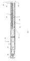
- FIG. 1 shown therein is a side view of a taped component processing machine 100, which includes a base structure 112, generally of a rectilinear configuration and comprising side, top and end cover plates.
- the base structure 112 is adapted to support tape reel shaft 115 through corresponding bores in the side plates of structure 112.
- the shaft 114 supports an electrical component tape reel 116 of a well-known configuration.
- the tape reel 116 stores a tape 118 which secures a plurality of electrical components 120, each having a plurality of leads emerging from generally the same side of the component.
- lead configuration is known as a radial lead configuration.
- the leads of the components 120 are secured to the tape 118, which includes a plurality of equally spaced apertures 122 which are useful in feeding the tape through the machine.
- the particular embodiment shown herein is adapted for lead-in-line components, although the machine can readily be adapted to offset parts by changing the cut clamp die elements.
- the spent tape travels through the machine and exits behind the tape reel 116, as shown in FIG. 1.
- the narrow footprint of the machine 100 is apparent in the top view of FIG. 2.
- the narrow footprint which may be on the order of three inches, is a significant advantage of the machine 100 since it allows the machine to be closely spaced in a work cell alongside other feeder machines, using only a relatively small amount of space.
- In a component assembly work cell there may be many feeders which must be spaced so as to be accessible to the component insertion robotic equipment. Therefore, the closer the feeder devices can be spaced relative to adjacent feeders, the more feeders can be arranged around the work cell and the more flexible the insertion system.
- the tape 118 is guided over a guide bar 117 and is reeved around an indexer wheel 150 (FIG. 4), undergoing a 90° twist, the tape being rotated from a substantially horizontal orientation at the tape reel to a substantially vertical orientation at the wheel 150.
- the tape 118 is driven by the indexer wheel 150 to sequentially position successive ones of the electrical components 120 secured on the tape 118 at a lead cutting station generally indicated as station 130 in FIG. 2.
- the station 130 is preferably located on the longitudinal center axis 112D of the machine.
- the leads are clamped and cut to a predetermined length, and the component is then ready for removal, either manually or preferably by automated equipment.
- the component is picked up by robotic equipment and inserted in a circuit board.
- the spent tape is guided through a slot 113C formed between inner and outer plate members 113A and 113B to exit the machine from the rear thereof.
- Both the spent tape and separating paper strip can be collected conveniently in a single receptacle disposed under the rear of the machine.
- FIG. 3 is a partial enlarged top view of the machine 100 showing the cutting station 130 in more detail.
- the clamping and cutting dies comprise a fixed clamp and cutter element 144, a movable comb-clamp element 148, and a movable cutter element 160.
- the comb-clamp element 148 is adapted for an in-line component having two in-line leads.
- the comb-clamp element 148 has two V-shaped indentations 148A which capture and clamp the component leads.
- the fixed cutter blade element 144 is secured to a cover plate 140 by threaded fastener 145.
- the indexer drive wheel 150 rotates about axis 146 beneath the plate 140, and drives the tape 118 so that successive ones of the components 120 are positioned at the station 130 adjacent the fixed cutter 144.
- the moving comb 148 and cutter element 160 are actuated to slide in juxtaposition with the fixed cutter 144, thereby effecting the lead clamping and cutting.
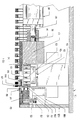
- FIG. 4 is a cross-sectional view taken along line 4-4 of FIG. 3, and illustrates the cutting station elements and the indexer wheel 150.
- the indexer wheel 150 includes a plurality of radially extending sprocket pins 152 extending outwardly from the periphery of the wheel and spaced to engage in holes 122 spaced in the tape 118, so that the pins 152 are accepted in the holes 118.
- the wheel 150 is mounted on a drive shaft 154, which is in turn driven by the pneumatic indexer assembly 156.
- the assembly 156 is a commercially available device.
- the indexer model 60289X1 marketed by Rotomation, Inc., Daytona, Florida, can be used as the assembly 156.
- the fixed cutter 144 is provided with a cantilevered lip section 144A.
- the comb-clamp element 148 is mounted on a comb-clamp carriage 157, in turn mounted on a cut element carriage 170, and is actuated to move against the lip section 144A of the fixed cutter 144, in a compound motion with the moving cutter 160 as the cutter 160 and comb 148 are moved from left to right.
- the comb-clamp element 148 stops against the lip 144A compressing spring 164, which provides a clamping force on the leads of the component 120..
- the moving cutter 160 is arranged to slide under the lip 144A, shearing the leads of the component 120 by the combined action of the lip 144A and the cutter 160. This is shown more clearly in FIG. 11.
- the top plate 140 is secured to support block fixture 137 by threaded fasteners 141.
- the fixed cutter blade is in turned secured to the top plate 140 by threaded fasteners 141.
- the moving cutter element 160 is mounted on the cut carriage 170.
- the carriage 170 in turn is coupled to a double-acting pnuematic cylinder 180 via the cylinder piston 182 and a tie bar 184 and link assembly.
- the carriage 170 is mounted for sliding movement on a pair of parallel ways or shafts 170A and 170B.
- the pneumatic cylinder 180 is double acting, and can be actively driven in either axial direction.
- the carriage 170 can be moved to pull the carriage 170 to bring the cutter element 160 and the comb-clamp element 148 through a clamp and cut stroke movement to clamp and cut the leads of a component 120, and thereafter to retract the carriage 170 to release the component and allow a fresh component to be brought into position at the station 130.
- the carriage 170 elements and the links 190A and 190B are arranged to slide along axes which are substantially parallel to the machine center axis 112D.
- the cylinder 180 extends substantially along the center axis 112D, and is secured to the feeder structure. The arrangement of the carriage elements, the links and cylinder contribute to the narrowness of the machine's footprint.
- the piston 182 is fastened to the tie bar 184 by a screw fastener 186.
- the tie bar 184 connects between two links 190A and 190B which extend along opposite sides of the wheel 150 and connect between the tie bar 184 and the cut carriage 170, transferring the translating forces between the piston-tie bar arrangement and the cut carriage 170.
- the machine 100 further comprises a "component present" sensor which provides a signal in the event the comb-clamp element 164 is fully extended and is not stopped by component leads at the lead cutting station 130.
- the sensor includes a Hall-effect switch 151, actuated by element 153 carried by the comb carriage (FIG. 4).
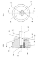
- the indexer wheel 150 is removably secured on the shaft 154 by a half-moon hub lock arrangement, shown in FIG. 5 and in more detail in FIGS. 7-9.
- a shaft bore 202 is formed on the center axis 146 of the wheel 150 and to a predetermined depth into the surface 150A of the wheel 150 to receive the shaft 154.
- a crescent-shaped hub lock cutout is formed through the surface 150A of the wheel 150 offset from the center axis 146 thereof. The cutout extends into the wheel 105 to a depth equal to the depth of the shaft bore 202.
- a hub lock element 192 having a cross-sectional configuration generally matching the cross-sectional configuration of the cutout is fitted into the cutout opening.
- the interior concave surface 192A of the hub lock element is curved to substantially match the shaft 154 curvature.
- a threaded bore 196 is formed through surfaces 150B of the indexer wheel, offset from the center axis 146, and extends into the wheel and into the combined structure of the lock element 192 and the wheel 150, centered on the parting line 150C between the element 192 and the wheel 150, as shown in FIGS. 7-9.
- the threaded bore 196 is formed to a predetermined depth and terminates in a taper, typically at about eight degrees, i.e., runout of the tap in the bottom of the threaded bore 196 is about eight degrees.
- the purpose of the taper is to provide the hub locking action when a threaded bolt 198 is screwed into the bore 196.
- the bolt end bears against the taper surface of the two bore-defining portions of the hub lock 192 and wheel 150, tending to force the hub lock 192 toward the shaft bore 202, thereby clamping the hub locking element 192 and the circumferential area of the wheel adjacent the shaft 154 tightly against the shaft 154.
- the depth of insertion of the shaft 154 into the shaft bore 202 is controlled by a second threaded bolt 204 threaded into a threaded bore formed on center with the axis 146 of the wheel 154, extending through the surface 150B and through the wheel 150 into the shaft opening 202.
- the bolt end 204 when extending into the opening 202, forms a stop surface for limiting the travel of the shaft 154 into the opening 202. This allows quick and convenient adjustment accessible from the top surface 112C of the machine 100 of the cut length of the components leads, since the tape 118 is engaged by the sprocket pins 152 and will be carried upwardly or downwardly with the axial position of the wheel 150 on its drive shaft 154.
- a further feature permitting adjustment of the wheel 150 is that two key slots 202A and 202B (FIG. 8) are formed in the wheel 150 adjacent the bore 202 to be engaged by a key 154A fitted into shaft 154 for aligning the wheel 150 to the shaft 154.
- the key slots 202A, 202B are offset about the periphery of bore 202 by 1/2 pitch, i.e., one-half the angular spacing between holes in the tape, so that the key slot 202A positions the tape for one possible tape configuration, and the other slot 202B positions the tape for the other possible tape configuration. In a preferred embodiment, this spacing between slots 202A and 202B is 15°.
- a major advantage of the means provided to adjust the machine to different lead cut lengths and for different tape configurations is that the adjustment means is made readily available from the top surface 112C of the machine 100.
- An access opening 208 is formed in the top plate 140, allowing tool access to both adjusting screws 198 and 204.
- the lead cut length may be adjusted by loosening the bolt 198, and by advancing or retracting the bolt 204 to raise or lower the wheel in relation to the shaft end.
- the screw 198 is then retightened to clamp the wheel on the shaft 154.
- the wheel 150 may be readily removed as well, either for maintenance or to move to a different key slot to adjust to a different tape configuration.
- top plate fasteners 141 and top plate 140 are removed, and the hub locking screw 198 loosened.
- the wheel 150 is then simply withdrawn from the shaft 154, and may be repositioned on either key slot, depending on the tape configuration.
- the machine 100 may be adjusted quickly and without the time and expense required to remove the machine to carry out such adjustments. As a result machine down time due to adjustment to differing component lead lengths or tape configurations is held to a minimum.
- FIG. 10 shows a partial side view of the machine 100 with the side plate 112E removed.
- the link 190A connecting the tie bar 184 to the cut carriage 170 is connected to the tie bar 184 by fastener 210 and to the carriage 170 by pivot 212.
- a second link 190B (not visible in FIG. 10) connects the respective sides of the bar 184 and the carriage 170.
- FIG. 11 shows an exploded diagrammatic illustration of elements of the comb-clamp carriage 157 and the cut carriage 170.
- the cut carriage 170 is mounted for sliding movement on the two parallel ways 170A and 170B, which fit into corresponding bores 170C and 170D formed in the carriage 170.
- the links 190A and 190B connect to the carriage 170, and provide drive forces to slide the carriage 170 along the ways 170A and 170B to cut the lead in one direction and to withdraw the comb-clamp carriage 157and the cut carriage 170 in the other direction.
- the clamp-comb carriage 157 is mounted for sliding movement on parallel ways 157A and 157B carried by the cut carriage 170.
- the ways 157A and 157B are fitted into corresponding bores 157C and 157D formed in the carriage 157.
- the position of the carriage 157 is biased by clamp spring 164, which is compressed between surface 157E of carriage 157 and 170E of carriage 170.
- the spring is further compressed as the carriage 170 is moved to cut the leads, since the comb-clamp element 148 is stopped against the lip 144A of the fixed cutter elements 144.
- the comb-clamp carriage 157 to slide in relation to carriage 170 when the element 148 contacts the lip 144A, so that the comb- clamp die 148 exerts only a clamping, and not a cutting, force on the component leads.
- the spring bias provides the lead clamping force.
- the cylinder 180 and the pneumatic index 156 are actuated by pneumatic valves (not shown) in the conventional manner.
- a radial lead component feeder has been described, and has the following important advantages:
Abstract
Description
- The disclosed invention generally relates to apparatus for forming the leads of taped electrical components, and is more particularly directed to apparatus for cutting the leads of taped components having radial leads.
- For utilization in the fabrication of electrical circuits, electronic components such as transistors, capacitors, and resistors are provided by component manufacturers with their leads secured to an elongated tape which includes generally equally spaced feed holes. A particular type of component configuration, generally known as radial lead components, have leads which emerge from generally the same side or portion of the component.
- For utilization, taped electronic components are separated from the tape by cutting the leads; for some component types, the cut leads are appropriately formed for insertion. The cutting and forming has generally been performed with different types of machinery. For example, dedicated machines cut and form leads, and also insert the components. However, such dedicated machinery generally are capable of processing only a specific component, require a large amount of space, and not readily utilized with robotic component insertion.
- Another example of taped component lead cutting machinery are machines which deposit or place the processed components in a container for manual retrieval and insertion. Such machinery are also not readily utilized with robotic component insertion, and may require a large amount of space.
- A further example of taped component lead cutting machinery are machines originally designed for manual component retrieval and insertion, and which are modified for use with robotic component insertion. Such machinery, however, tend to be compromises since they are being forced to operate in a manner not contemplated by their original designs.
- A radial lead electrical component feeder is disclosed in U.S. Patent 4,757,600, issued to Gregory W. Holcomb, one of the applicants herein. The apparatus disclosed therein cuts and forms the leads. A commercial embodiment of a feeder mechanism embodying the invention of U.S. Patent 4,757,600 has been marketed by Chad Industries,, Orange, California, as its model "RC" and "RCO" feeders. This feeder mechanism is adjustable to different component phasing on the tape by adjusting the stop position of the
piston rod 153 ofair cylinder 151. Adjustments for lead lengths are made by changing shim heights supporting the tape ratchet. While the apparatus disclosed in this patent works well and has many desirable features, it is relatively expensive to manufacture. - It would therefore be an advantage to provide a reliable apparatus for cutting the leads of taped radial lead electronic components for use with robotic component insertion, which is readily and easily adjusted to cut the leads to a desired length, and to adjust to different tape configurations, and which is relatively inexpensive to manufacture and has a relatively narrow footprint.
- A component feeder apparatus is disclosed for clamping and cutting to a predetermined length the leads of electrical components secured to tape. The apparatus includes a rotary tape drive means for driving the tape to sequentially position components at a lead clamping and cutting station. The rotary drive means includes a drive wheel having means for engaging the tape about the wheel periphery and mounted for rotation about a wheel axis. The clamping and cutting station is disposed at the periphery of the wheel and on the longitudinal center line of the apparatus, with the wheel axis extending at a direction normal to the center line. The lead clamping station comprises means for clamping at least one lead of the component positioned at the station and means for cutting to a predetermined length the component leads. The apparatus further comprises means for guiding the tape to the rotary tape drive means and means for guiding the spent tape away from the drive means after the leads of respective successive components have been clamped and cut. After the lead are cut at the station, the component is ready for robotic pick-up.
- The apparatus has a narrow footprint and is therefore space efficient. Means are provided for readily adjusting the apparatus to different lead cut lengths and to different tape configurations. The lead length adjusting means comprises a hub lock element actuated by a threaded member extending parallel to but offset from the wheel axis, and accessible readily from the top surface of the apparatus.
- The advantages and features of the disclosed invention will readily be appreciated by persons skilled in the art from the following detailed description when read in conjunction with the drawing wherein:
- FIG. 1 is a side view of a taped component processing machine which utilizes the taped component lead cutting apparatus of the invention.
- FIG. 2 is a top view of the apparatus of FIG. 1.
- FIG. 3 is an enlarge partial top view of the apparatus of FIG. 1.
- FIG. 4 is a side cross-sectional view taken along line 4-4 of FIG. 3.
- FIG. 5 is a side cross-sectional view taken along line 5-5 of FIG. 3.
- FIG. 6 is a side cross-sectional view taken along line 6-6 of FIG. 3.
- FIG. 7 is an exploded view illustrating the indexer wheel and hub lock elements employed in the apparatus of FIG. 1.
- FIG. 8 is a top view of the indexer wheel.
- FIG. 9 is a cross-sectional view of the indexer wheel taken along line 9-9 of FIG. 8.
- FIG. 10 is a partial side view of the apparatus of FIG. 1 with the side cover removed.
- FIG. 11 is an exploded view illustrating the clamp-comb carriage and the cut carriage of the apparatus of FIG. 1.
- FIG. 12 is an enlarged cross-sectional view of the clamping and cutting station, illustrative of the interrelationship of the cutting and clamping dies.
- In the following detailed description and in the several figures, like elements are identified with like reference numerals.
- Referring now to FIG. 1, shown therein is a side view of a taped
component processing machine 100, which includes abase structure 112, generally of a rectilinear configuration and comprising side, top and end cover plates. Thebase structure 112 is adapted to support tape reel shaft 115 through corresponding bores in the side plates ofstructure 112. Theshaft 114 supports an electricalcomponent tape reel 116 of a well-known configuration. - The
tape reel 116 stores atape 118 which secures a plurality ofelectrical components 120, each having a plurality of leads emerging from generally the same side of the component. As is well known, such lead configuration is known as a radial lead configuration. The leads of thecomponents 120 are secured to thetape 118, which includes a plurality of equallyspaced apertures 122 which are useful in feeding the tape through the machine. The particular embodiment shown herein is adapted for lead-in-line components, although the machine can readily be adapted to offset parts by changing the cut clamp die elements. The spent tape travels through the machine and exits behind thetape reel 116, as shown in FIG. 1. - The narrow footprint of the
machine 100 is apparent in the top view of FIG. 2. The narrow footprint, which may be on the order of three inches, is a significant advantage of themachine 100 since it allows the machine to be closely spaced in a work cell alongside other feeder machines, using only a relatively small amount of space. In a component assembly work cell there may be many feeders which must be spaced so as to be accessible to the component insertion robotic equipment. Therefore, the closer the feeder devices can be spaced relative to adjacent feeders, the more feeders can be arranged around the work cell and the more flexible the insertion system. - The
tape 118 is guided over aguide bar 117 and is reeved around an indexer wheel 150 (FIG. 4), undergoing a 90° twist, the tape being rotated from a substantially horizontal orientation at the tape reel to a substantially vertical orientation at thewheel 150. Thetape 118 is driven by theindexer wheel 150 to sequentially position successive ones of theelectrical components 120 secured on thetape 118 at a lead cutting station generally indicated asstation 130 in FIG. 2. In order to minimize the width of the machine footprint, thestation 130 is preferably located on the longitudinal center axis 112D of the machine. At thisstation 130, the leads are clamped and cut to a predetermined length, and the component is then ready for removal, either manually or preferably by automated equipment. In a preferred application, the component is picked up by robotic equipment and inserted in a circuit board. - The spent tape is guided through a
slot 113C formed between inner andouter plate members 113A and 113B to exit the machine from the rear thereof. This simplifies the collection of scrap paper resulting from operation, since the tape layers on thereel 116 are usually separated by a paper strip which falls away at the rear of the machine for collection. Both the spent tape and separating paper strip can be collected conveniently in a single receptacle disposed under the rear of the machine. - FIG. 3 is a partial enlarged top view of the
machine 100 showing the cuttingstation 130 in more detail. The clamping and cutting dies comprise a fixed clamp andcutter element 144, a movable comb-clamp element 148, and amovable cutter element 160. The comb-clamp element 148 is adapted for an in-line component having two in-line leads. Thus, the comb-clamp element 148 has two V-shapedindentations 148A which capture and clamp the component leads. - The fixed
cutter blade element 144 is secured to acover plate 140 by threadedfastener 145. Theindexer drive wheel 150 rotates aboutaxis 146 beneath theplate 140, and drives thetape 118 so that successive ones of thecomponents 120 are positioned at thestation 130 adjacent the fixedcutter 144. As will be described in further detail, the movingcomb 148 andcutter element 160 are actuated to slide in juxtaposition with the fixedcutter 144, thereby effecting the lead clamping and cutting. - FIG. 4 is a cross-sectional view taken along line 4-4 of FIG. 3, and illustrates the cutting station elements and the
indexer wheel 150. Theindexer wheel 150 includes a plurality of radially extending sprocket pins 152 extending outwardly from the periphery of the wheel and spaced to engage inholes 122 spaced in thetape 118, so that thepins 152 are accepted in theholes 118. Thewheel 150 is mounted on adrive shaft 154, which is in turn driven by thepneumatic indexer assembly 156. Theassembly 156 is a commercially available device. For example, the indexer model 60289X1, marketed by Rotomation, Inc., Daytona, Florida, can be used as theassembly 156. - The fixed
cutter 144 is provided with acantilevered lip section 144A. The comb-clamp element 148 is mounted on a comb-clamp carriage 157, in turn mounted on acut element carriage 170, and is actuated to move against thelip section 144A of the fixedcutter 144, in a compound motion with the movingcutter 160 as thecutter 160 and comb 148 are moved from left to right. The comb-clamp element 148 stops against thelip 144A compressing spring 164, which provides a clamping force on the leads of thecomponent 120.. The movingcutter 160 is arranged to slide under thelip 144A, shearing the leads of thecomponent 120 by the combined action of thelip 144A and thecutter 160. This is shown more clearly in FIG. 11. - The
top plate 140 is secured to supportblock fixture 137 by threadedfasteners 141. The fixed cutter blade is in turned secured to thetop plate 140 by threadedfasteners 141. - The moving
cutter element 160 is mounted on thecut carriage 170. Thecarriage 170 in turn is coupled to a double-actingpnuematic cylinder 180 via thecylinder piston 182 and atie bar 184 and link assembly. Thecarriage 170 is mounted for sliding movement on a pair of parallel ways orshafts 170A and 170B. Thepneumatic cylinder 180 is double acting, and can be actively driven in either axial direction. Thus, by actuating thepneumatic cylinder 180, thecarriage 170 can be moved to pull thecarriage 170 to bring thecutter element 160 and the comb-clamp element 148 through a clamp and cut stroke movement to clamp and cut the leads of acomponent 120, and thereafter to retract thecarriage 170 to release the component and allow a fresh component to be brought into position at thestation 130. Thecarriage 170 elements and thelinks cylinder 180 extends substantially along the center axis 112D, and is secured to the feeder structure. The arrangement of the carriage elements, the links and cylinder contribute to the narrowness of the machine's footprint. - The
piston 182 is fastened to thetie bar 184 by ascrew fastener 186. Thetie bar 184 connects between twolinks wheel 150 and connect between thetie bar 184 and thecut carriage 170, transferring the translating forces between the piston-tie bar arrangement and thecut carriage 170. - The
machine 100 further comprises a "component present" sensor which provides a signal in the event the comb-clamp element 164 is fully extended and is not stopped by component leads at thelead cutting station 130. The sensor includes a Hall-effect switch 151, actuated byelement 153 carried by the comb carriage (FIG. 4). - The
indexer wheel 150 is removably secured on theshaft 154 by a half-moon hub lock arrangement, shown in FIG. 5 and in more detail in FIGS. 7-9. A shaft bore 202 is formed on thecenter axis 146 of thewheel 150 and to a predetermined depth into thesurface 150A of thewheel 150 to receive theshaft 154. A crescent-shaped hub lock cutout is formed through thesurface 150A of thewheel 150 offset from thecenter axis 146 thereof. The cutout extends into the wheel 105 to a depth equal to the depth of the shaft bore 202. Ahub lock element 192 having a cross-sectional configuration generally matching the cross-sectional configuration of the cutout is fitted into the cutout opening. The interior concave surface 192A of the hub lock element is curved to substantially match theshaft 154 curvature. - A threaded
bore 196 is formed throughsurfaces 150B of the indexer wheel, offset from thecenter axis 146, and extends into the wheel and into the combined structure of thelock element 192 and thewheel 150, centered on theparting line 150C between theelement 192 and thewheel 150, as shown in FIGS. 7-9. The threaded bore 196 is formed to a predetermined depth and terminates in a taper, typically at about eight degrees, i.e., runout of the tap in the bottom of the threadedbore 196 is about eight degrees. The purpose of the taper is to provide the hub locking action when a threadedbolt 198 is screwed into thebore 196. As thebolt 198 reaches and advances into thetaper 200 portion of the bore, the bolt end bears against the taper surface of the two bore-defining portions of thehub lock 192 andwheel 150, tending to force thehub lock 192 toward the shaft bore 202, thereby clamping thehub locking element 192 and the circumferential area of the wheel adjacent theshaft 154 tightly against theshaft 154. - The depth of insertion of the
shaft 154 into the shaft bore 202 is controlled by a second threadedbolt 204 threaded into a threaded bore formed on center with theaxis 146 of thewheel 154, extending through thesurface 150B and through thewheel 150 into theshaft opening 202. Thebolt end 204, when extending into theopening 202, forms a stop surface for limiting the travel of theshaft 154 into theopening 202. This allows quick and convenient adjustment accessible from thetop surface 112C of themachine 100 of the cut length of the components leads, since thetape 118 is engaged by the sprocket pins 152 and will be carried upwardly or downwardly with the axial position of thewheel 150 on itsdrive shaft 154. - A further feature permitting adjustment of the
wheel 150 is that two key slots 202A and 202B (FIG. 8) are formed in thewheel 150 adjacent thebore 202 to be engaged by a key 154A fitted intoshaft 154 for aligning thewheel 150 to theshaft 154. This permits themachine 100 to be easily adapted to the particular configuration of the sprocket holes 122 in thetape 118. Some tapes are loaded with components so that theholes 122 are located between the components, while other tapes are loaded so that the leads of a component straddle a hole. The key slots 202A, 202B are offset about the periphery ofbore 202 by 1/2 pitch, i.e., one-half the angular spacing between holes in the tape, so that the key slot 202A positions the tape for one possible tape configuration, and the other slot 202B positions the tape for the other possible tape configuration. In a preferred embodiment, this spacing between slots 202A and 202B is 15°. - A major advantage of the means provided to adjust the machine to different lead cut lengths and for different tape configurations is that the adjustment means is made readily available from the
top surface 112C of themachine 100. An access opening 208 is formed in thetop plate 140, allowing tool access to both adjustingscrews bolt 198, and by advancing or retracting thebolt 204 to raise or lower the wheel in relation to the shaft end. Thescrew 198 is then retightened to clamp the wheel on theshaft 154. Thewheel 150 may be readily removed as well, either for maintenance or to move to a different key slot to adjust to a different tape configuration. To accomplish the removal, thetop plate fasteners 141 andtop plate 140 are removed, and thehub locking screw 198 loosened. Thewheel 150 is then simply withdrawn from theshaft 154, and may be repositioned on either key slot, depending on the tape configuration. Thus, themachine 100 may be adjusted quickly and without the time and expense required to remove the machine to carry out such adjustments. As a result machine down time due to adjustment to differing component lead lengths or tape configurations is held to a minimum. - FIG. 10 shows a partial side view of the
machine 100 with the side plate 112E removed. Thelink 190A connecting thetie bar 184 to thecut carriage 170 is connected to thetie bar 184 byfastener 210 and to thecarriage 170 bypivot 212. Asecond link 190B (not visible in FIG. 10) connects the respective sides of thebar 184 and thecarriage 170. - FIG. 11 shows an exploded diagrammatic illustration of elements of the comb-
clamp carriage 157 and thecut carriage 170. Thecut carriage 170 is mounted for sliding movement on the twoparallel ways 170A and 170B, which fit into correspondingbores 170C and 170D formed in thecarriage 170. Thelinks carriage 170, and provide drive forces to slide thecarriage 170 along theways 170A and 170B to cut the lead in one direction and to withdraw the comb-clamp carriage 157and thecut carriage 170 in the other direction. The clamp-comb carriage 157 is mounted for sliding movement onparallel ways 157A and 157B carried by thecut carriage 170. Theways 157A and 157B are fitted intocorresponding bores 157C and 157D formed in thecarriage 157. The position of thecarriage 157 is biased byclamp spring 164, which is compressed betweensurface 157E ofcarriage carriage 170. The spring is further compressed as thecarriage 170 is moved to cut the leads, since the comb-clamp element 148 is stopped against thelip 144A of the fixedcutter elements 144. The comb-clamp carriage 157 to slide in relation tocarriage 170 when theelement 148 contacts thelip 144A, so that the comb-clamp die 148 exerts only a clamping, and not a cutting, force on the component leads. The spring bias provides the lead clamping force. - The
cylinder 180 and thepneumatic index 156 are actuated by pneumatic valves (not shown) in the conventional manner. - A radial lead component feeder has been described, and has the following important advantages:
- 1. The machine has a narrow footprint resulting from the in-line configuration of the indexer wheel and lead clamping and cutting station elements.
- 2. The mechanical components of the machine are relatively simple, thereby providing reliable machine operation and relatively lower cost manufacture.
- 3. The machine can be quickly adjusted to cut the component leads to particular desired lengths without disassembly of the machine.
- 4. The machine can be readily adjusted to different tape configurations by removing and reorienting the tape index wheel.
- It is understood that the above-described embodiment is merely illustrative of the possible specific embodiments which may represent principles of the present invention. Other arrangements may readily be devised in accordance with these principles by those skilled in the art without departing from the scope of the invention.
Claims (15)
a rotary tape drive means for driving the tape (118) on which the electrical components (120) are secured to sequentially position components at a lead clamping and cutting station (130), said drive means comprising a drive wheel (150) having means (152) for engaging the tape about the wheel periphery and mounted for rotation about a wheel axis (146);
a lead clamping and cutting station (130) comprising means for clamping at least one lead of the component (120) positioned at the station and means for cutting to a predetermined length the component leads, said station (130) being disposed at the periphery of said wheel;
means (116, 117) for guiding the tape to which the components are secured to the rotary tape drive means and means (113A, 113B, 113C) for guiding the spent tape away from the drive means after the leads of respective successive components (120) have been clamped and cut to said predetermined length.
a fixed cutter blade (144) disposed at the lead cutting station (130);
a moving cutter blade (160) mounted on a cut carriage (170);
said cut carriage (170) arranged for sliding movement on support ways (170A, 170B) extending substantially parallel to the longitudinal feeder axis (112D);
drive means (180) for driving the cut carriage (170) to move the moving cutter blade (160) in juxtaposition with said fixed blade (144) to cut said component lead.
a hub lock opening defined in said element (150) to at least a predetermined depth, said opening formed adjacent to and partially opening into said shaft opening (202);
a hub lock element (192) disposed in said hub lock opening and having a first surface (192A) fitting adjacent said shaft opening, and a second surface (192B) disposed on another side of said hub lock element (192);
a threaded bore (196) defined in the combined structure of said shaft-mounted element (150) substantially parallel to said hub lock element (192), there being a parting line defined by adjacent threaded surfaces of the element (150) and hub lock element (192), said bore (196) extending a predetermined depth and terminating in an inward taper of the threaded bore; and
a threaded member (198) adapted to be threadingly received in said threaded bore (196), wherein as the tip of the threaded member (198) reaches the taper, the hub lock element is forced against said shaft (154) and tends to lock the element (150) to the shaft (154).
Applications Claiming Priority (2)
| Application Number | Priority Date | Filing Date | Title |
|---|---|---|---|
| US07/374,159 US5024129A (en) | 1989-06-29 | 1989-06-29 | Radial lead component feeder having a narrow footprint |
| US374159 | 1995-01-17 |
Publications (2)
| Publication Number | Publication Date |
|---|---|
| EP0405977A1 true EP0405977A1 (en) | 1991-01-02 |
| EP0405977B1 EP0405977B1 (en) | 1994-05-18 |
Family
ID=23475561
Family Applications (1)
| Application Number | Title | Priority Date | Filing Date |
|---|---|---|---|
| EP90307088A Expired - Lifetime EP0405977B1 (en) | 1989-06-29 | 1990-06-28 | Radial lead component feeder |
Country Status (4)
| Country | Link |
|---|---|
| US (1) | US5024129A (en) |
| EP (1) | EP0405977B1 (en) |
| CA (1) | CA2020087C (en) |
| DE (1) | DE69008939T2 (en) |
Cited By (4)
| Publication number | Priority date | Publication date | Assignee | Title |
|---|---|---|---|---|
| EP0520295A1 (en) * | 1991-06-26 | 1992-12-30 | Siemens Nixdorf Informationssysteme Aktiengesellschaft | Method and device for forming external connections in surface mounted components |
| CN107926141A (en) * | 2015-07-24 | 2018-04-17 | 富士机械制造株式会社 | Element feeder |
| CN110741745A (en) * | 2017-06-14 | 2020-01-31 | 株式会社富士 | Electronic component mounting machine |
| EP3820265A1 (en) | 2019-11-08 | 2021-05-12 | Semo | Method and device for cutting a radial electronic component |
Families Citing this family (2)
| Publication number | Priority date | Publication date | Assignee | Title |
|---|---|---|---|---|
| JP6535883B2 (en) * | 2016-10-11 | 2019-07-03 | パナソニックIpマネジメント株式会社 | Component supply device and component mounter |
| WO2019146081A1 (en) * | 2018-01-26 | 2019-08-01 | 株式会社Fuji | Radial tape feeder |
Citations (6)
| Publication number | Priority date | Publication date | Assignee | Title |
|---|---|---|---|---|
| DE2910633A1 (en) * | 1979-03-17 | 1980-09-18 | Thomas Weresch | Transistor terminal lead trimmer - has guide groove perpendicular to tools and in line with friction feed wheel |
| DE2920059A1 (en) * | 1979-05-18 | 1980-11-20 | Thomas Weresch | Bender and crimper for connecting wires of electrical components - has storage section for components and wire shearing tool and has synchroniser for reciprocating movements |
| EP0081668A2 (en) * | 1981-12-10 | 1983-06-22 | Georg Sillner | Device for girding electrical components |
| EP0141279A2 (en) * | 1983-10-20 | 1985-05-15 | Alfred Lemmer | Apparatus for cutting lead wires of components penetrating a printed circuit board |
| DE3718938A1 (en) * | 1986-06-06 | 1988-05-26 | Emhart Ind | MECHANICS FOR CENTERING AND CUTTING THE CONNECTIONS OF ELECTRICAL COMPONENTS |
| US4757600A (en) * | 1987-07-27 | 1988-07-19 | Holcomb Gregory W | Radial lead electrical component feeder |
Family Cites Families (5)
| Publication number | Priority date | Publication date | Assignee | Title |
|---|---|---|---|---|
| US3701298A (en) * | 1970-07-15 | 1972-10-31 | Martin G Heller | De-reeling apparatus for electrical components |
| US4015322A (en) * | 1976-06-03 | 1977-04-05 | Comatel - Comptoir European De Materiel Electronique | Apparatus for locating connectors onto a circuit board |
| US4205473A (en) * | 1978-09-01 | 1980-06-03 | Wilson Hugh R | Telescope mount for firearms |
| US4245385A (en) * | 1979-07-09 | 1981-01-20 | Universal Instruments Corporation | Radial lead component insertion machine |
| US4780950A (en) * | 1987-08-24 | 1988-11-01 | Holcomb Gregory W | Axial lead electrical component feeder |
-
1989
- 1989-06-29 US US07/374,159 patent/US5024129A/en not_active Expired - Lifetime
-
1990
- 1990-06-28 DE DE69008939T patent/DE69008939T2/en not_active Expired - Fee Related
- 1990-06-28 EP EP90307088A patent/EP0405977B1/en not_active Expired - Lifetime
- 1990-06-28 CA CA002020087A patent/CA2020087C/en not_active Expired - Fee Related
Patent Citations (6)
| Publication number | Priority date | Publication date | Assignee | Title |
|---|---|---|---|---|
| DE2910633A1 (en) * | 1979-03-17 | 1980-09-18 | Thomas Weresch | Transistor terminal lead trimmer - has guide groove perpendicular to tools and in line with friction feed wheel |
| DE2920059A1 (en) * | 1979-05-18 | 1980-11-20 | Thomas Weresch | Bender and crimper for connecting wires of electrical components - has storage section for components and wire shearing tool and has synchroniser for reciprocating movements |
| EP0081668A2 (en) * | 1981-12-10 | 1983-06-22 | Georg Sillner | Device for girding electrical components |
| EP0141279A2 (en) * | 1983-10-20 | 1985-05-15 | Alfred Lemmer | Apparatus for cutting lead wires of components penetrating a printed circuit board |
| DE3718938A1 (en) * | 1986-06-06 | 1988-05-26 | Emhart Ind | MECHANICS FOR CENTERING AND CUTTING THE CONNECTIONS OF ELECTRICAL COMPONENTS |
| US4757600A (en) * | 1987-07-27 | 1988-07-19 | Holcomb Gregory W | Radial lead electrical component feeder |
Cited By (7)
| Publication number | Priority date | Publication date | Assignee | Title |
|---|---|---|---|---|
| EP0520295A1 (en) * | 1991-06-26 | 1992-12-30 | Siemens Nixdorf Informationssysteme Aktiengesellschaft | Method and device for forming external connections in surface mounted components |
| CN107926141A (en) * | 2015-07-24 | 2018-04-17 | 富士机械制造株式会社 | Element feeder |
| EP3328177A4 (en) * | 2015-07-24 | 2018-05-30 | Fuji Machine Mfg. Co., Ltd. | Component feeder |
| CN110741745A (en) * | 2017-06-14 | 2020-01-31 | 株式会社富士 | Electronic component mounting machine |
| CN110741745B (en) * | 2017-06-14 | 2021-01-12 | 株式会社富士 | Electronic component mounting machine |
| EP3820265A1 (en) | 2019-11-08 | 2021-05-12 | Semo | Method and device for cutting a radial electronic component |
| FR3102944A1 (en) * | 2019-11-08 | 2021-05-14 | Semo | method and device for cutting a radial electronic component |
Also Published As
| Publication number | Publication date |
|---|---|
| CA2020087C (en) | 1999-08-24 |
| DE69008939T2 (en) | 1994-10-20 |
| CA2020087A1 (en) | 1990-12-30 |
| EP0405977B1 (en) | 1994-05-18 |
| US5024129A (en) | 1991-06-18 |
| DE69008939D1 (en) | 1994-06-23 |
Similar Documents
| Publication | Publication Date | Title |
|---|---|---|
| US6067828A (en) | Crimping apparatus | |
| CA2373085C (en) | Quickly adjustable multiple clamping system | |
| CA1135483A (en) | Radial lead inserting machine | |
| EP1534471A4 (en) | Locating assembly having an extendable clamping finger | |
| EP0405977B1 (en) | Radial lead component feeder | |
| US5771768A (en) | Hole punch with quick-change die assembly | |
| DE3726726C2 (en) | ||
| US3796363A (en) | Multiple component insertion apparatus | |
| KR20030028379A (en) | Space forming apparatus for a slide fastener chain | |
| EP0400284A2 (en) | Automated drilling station | |
| DE3923012C2 (en) | ||
| CN116275212B (en) | Vertical machining center | |
| US4757600A (en) | Radial lead electrical component feeder | |
| JP2824891B2 (en) | Front-end positioning device for bending machine | |
| EP0897658A2 (en) | Apparatus for automatic execution of operations in the fabrication of circuit boards or similar boards | |
| CN215919841U (en) | Automatic tool changing mechanism of tool magazine | |
| US4455044A (en) | Tool for picking up and inserting different length bolts | |
| KR100399584B1 (en) | Tape cutting machine | |
| US5064048A (en) | Board conveyor | |
| US4398658A (en) | High speed radial lead component sequencing and inserting machine | |
| CN217224212U (en) | Alignment and stable conveying device for welding of temperature sensor | |
| CN110961688A (en) | Clamp center hole drilling machine | |
| KR920006098B1 (en) | Punching equipment for block band material of watch | |
| CN113471786B (en) | Wire assembly machine | |
| KR100523098B1 (en) | Apparatus for coling of shavings of side-trimmer |
Legal Events
| Date | Code | Title | Description |
|---|---|---|---|
| PUAI | Public reference made under article 153(3) epc to a published international application that has entered the european phase |
Free format text: ORIGINAL CODE: 0009012 |
|
| AK | Designated contracting states |
Kind code of ref document: A1 Designated state(s): BE CH DE FR GB IT LI NL |
|
| 17P | Request for examination filed |
Effective date: 19901220 |
|
| 17Q | First examination report despatched |
Effective date: 19930712 |
|
| GRAA | (expected) grant |
Free format text: ORIGINAL CODE: 0009210 |
|
| AK | Designated contracting states |
Kind code of ref document: B1 Designated state(s): BE CH DE FR GB IT LI NL |
|
| PG25 | Lapsed in a contracting state [announced via postgrant information from national office to epo] |
Ref country code: IT Free format text: LAPSE BECAUSE OF FAILURE TO SUBMIT A TRANSLATION OF THE DESCRIPTION OR TO PAY THE FEE WITHIN THE PRE;WARNING: LAPSES OF ITALIAN PATENTS WITH EFFECTIVE DATE BEFORE 2007 MAY HAVE OCCURRED AT ANY TIME BEFORE 2007. THE CORRECT EFFECTIVE DATE MAY BE DIFFERENT FROM THE ONE RECORDED.SCRIBED TIME-LIMIT Effective date: 19940518 Ref country code: BE Effective date: 19940518 Ref country code: NL Effective date: 19940518 Ref country code: FR Effective date: 19940518 |
|
| REF | Corresponds to: |
Ref document number: 69008939 Country of ref document: DE Date of ref document: 19940623 |
|
| EN | Fr: translation not filed | ||
| NLV1 | Nl: lapsed or annulled due to failure to fulfill the requirements of art. 29p and 29m of the patents act | ||
| PLBE | No opposition filed within time limit |
Free format text: ORIGINAL CODE: 0009261 |
|
| STAA | Information on the status of an ep patent application or granted ep patent |
Free format text: STATUS: NO OPPOSITION FILED WITHIN TIME LIMIT |
|
| 26N | No opposition filed | ||
| REG | Reference to a national code |
Ref country code: GB Ref legal event code: IF02 |
|
| PGFP | Annual fee paid to national office [announced via postgrant information from national office to epo] |
Ref country code: GB Payment date: 20030625 Year of fee payment: 14 |
|
| PGFP | Annual fee paid to national office [announced via postgrant information from national office to epo] |
Ref country code: CH Payment date: 20030702 Year of fee payment: 14 |
|
| PGFP | Annual fee paid to national office [announced via postgrant information from national office to epo] |
Ref country code: DE Payment date: 20030710 Year of fee payment: 14 |
|
| PG25 | Lapsed in a contracting state [announced via postgrant information from national office to epo] |
Ref country code: GB Free format text: LAPSE BECAUSE OF NON-PAYMENT OF DUE FEES Effective date: 20040628 |
|
| PG25 | Lapsed in a contracting state [announced via postgrant information from national office to epo] |
Ref country code: LI Free format text: LAPSE BECAUSE OF NON-PAYMENT OF DUE FEES Effective date: 20040630 Ref country code: CH Free format text: LAPSE BECAUSE OF NON-PAYMENT OF DUE FEES Effective date: 20040630 |
|
| PG25 | Lapsed in a contracting state [announced via postgrant information from national office to epo] |
Ref country code: DE Free format text: LAPSE BECAUSE OF NON-PAYMENT OF DUE FEES Effective date: 20050101 |
|
| REG | Reference to a national code |
Ref country code: CH Ref legal event code: PL |
|
| GBPC | Gb: european patent ceased through non-payment of renewal fee |
Effective date: 20040628 |