EP0405679A1 - Autoadaptive equalization device for duobinary coded digital samples - Google Patents
Autoadaptive equalization device for duobinary coded digital samples Download PDFInfo
- Publication number
- EP0405679A1 EP0405679A1 EP90201663A EP90201663A EP0405679A1 EP 0405679 A1 EP0405679 A1 EP 0405679A1 EP 90201663 A EP90201663 A EP 90201663A EP 90201663 A EP90201663 A EP 90201663A EP 0405679 A1 EP0405679 A1 EP 0405679A1
- Authority
- EP
- European Patent Office
- Prior art keywords
- filter
- coefficients
- self
- signal
- adaptation
- Prior art date
- Legal status (The legal status is an assumption and is not a legal conclusion. Google has not performed a legal analysis and makes no representation as to the accuracy of the status listed.)
- Ceased
Links
Images
Classifications
-
- H—ELECTRICITY
- H04—ELECTRIC COMMUNICATION TECHNIQUE
- H04N—PICTORIAL COMMUNICATION, e.g. TELEVISION
- H04N5/00—Details of television systems
- H04N5/14—Picture signal circuitry for video frequency region
- H04N5/21—Circuitry for suppressing or minimising disturbance, e.g. moiré or halo
- H04N5/211—Ghost signal cancellation
-
- H—ELECTRICITY
- H04—ELECTRIC COMMUNICATION TECHNIQUE
- H04N—PICTORIAL COMMUNICATION, e.g. TELEVISION
- H04N7/00—Television systems
- H04N7/025—Systems for the transmission of digital non-picture data, e.g. of text during the active part of a television frame
- H04N7/035—Circuits for the digital non-picture data signal, e.g. for slicing of the data signal, for regeneration of the data-clock signal, for error detection or correction of the data signal
-
- H—ELECTRICITY
- H04—ELECTRIC COMMUNICATION TECHNIQUE
- H04N—PICTORIAL COMMUNICATION, e.g. TELEVISION
- H04N7/00—Television systems
- H04N7/08—Systems for the simultaneous or sequential transmission of more than one television signal, e.g. additional information signals, the signals occupying wholly or partially the same frequency band, e.g. by time division
- H04N7/083—Systems for the simultaneous or sequential transmission of more than one television signal, e.g. additional information signals, the signals occupying wholly or partially the same frequency band, e.g. by time division with signal insertion during the vertical and the horizontal blanking interval, e.g. MAC data signals
Definitions
- the present invention relates to a self-adaptive equalization device for processing digital samples coded for example in duobinary and transmitted by a quasi-stationary channel, device comprising a transverse digital filter, a circuit for estimating the error at the output of the filter, and an automaton to perform a process of self-adaptation of the coefficients of the digital filter.
- Such a device is used in digital communications systems.
- Viterbi decoder is less sensitive to intersymbol interference than a threshold decoder, but its performance is however not entirely sufficient.
- the invention is based on the idea of using a self-adjusting equalizer in a television decoder according to the D2-MAC standard and the observation that, with certain specific provisions concerning the initialization and the stopping of the self-adaptation process, it it is possible to reduce the number of quantization bits of the coefficients of the filter without causing convergence faults.
- the device comprises a decision element for stopping the process of repetitive adjustment of the coefficients when the value of the samples at the output of the device is included in a windows of a set of predetermined windows, and each of the coefficients of the filter is defined by a number of bits limited to eight or nine.
- the set of windows advantageously consists of three windows, one framing the normal level of a zero sample, another framing the normal level of a high sample, and the third framing the normal level of a low sample.
- the device comprises means for activating the self-adaptation process only during the periods of digital signal present at the start of each image line, and for short-circuiting the filter during the periods of time multiplex which follow the periods of duobinary signal.
- the filter is advantageously a filter with eight coefficients, asymmetrical, and whose main coefficient is the third.
- the device is provided with means for, during initialization, putting the main coefficient of the filter to one, and the others to zero.
- the automaton adds or subtracts from each of the filter coefficients an amount equal to a negative power of two. This can be done in a particularly simple way when this automaton has for this purpose, for each of the coefficients to be adapted, a counter whose capacity expressed in bits is equal to the number of bits for quantizing the coefficients of the filter, and in that the additions / subtractions are carried out by incrementing / decrementing the counting digits of the counter.
- the above decision element is constituted from a read-only memory called PROM to which the digital filtered signal is supplied as an address, and each of the possible addresses contains a digital value expressing the corresponding decision.
- the complete equalization device can be produced in an integrated form.
- the system of Figure 1 is described using digital signals encoded in duobinary, but it is obvious that the invention is applicable also with any signal encoded on several levels.
- the D2-MAC / packet signal received on an antenna 2 is retransmitted in amplitude modulation (modulation carried out in a distribution center 4) by a cable distribution network 14, to one or more televisions, one of which is shown in 5.
- Amplitude modulation with reduced sideband is used, which offers the advantage of occupying less space, for the same bandwidth of the modulating signal, than amplitude modulation with double band. Unfortunately, it can give rise to intersymbol interference if certain parameters of the transmission chain and of the demodulation do not respect the theoretical principles.
- the D2-MAC / packet signal is recovered in baseband on the scart socket of amplitude modulation receiver 5 and with reduced sideband (so-called videocomposite output).
- the signals are processed, in order to be decoded there, in element 7 and the image signals decoded, with the sound signals and the synchronization signals are returned to the terminals of the aforesaid SCART socket.
- the signal to be corrected by the equalizer of the invention is the duobinary part of the time multiplex of the D2-MAC / packet signal.
- the equalizer is therefore located in element 7 upstream of the duobinary data decoding circuit; it is preceded by an analog / digital converter.
- the input signal Xk (k is the time index of the sample) is brought to a transverse digital filter 27.
- the filtered signal y k which leaves it is brought to a threshold comparator 33 in which the signal y k is compared with two thresholds L placed at mid-amplitude of each of the polarities of the "eye diagram" of the received signal (FIG. 3), and the result of the comparison makes it possible to decide on the normalized value (low, zero, high) to assign to the signal.
- the "decided" signal â k is the useful signal. It is brought to an element 34 which calculates the error, called e k , for each sample.
- This error is the difference between the "decided" signal which has a normalized amplitude, and the filtered signal y k .
- the error e k is supplied to an automaton 35.
- the latter adapts the coefficients of the filter in order to reduce the mean square error. It provides the filter with the N coefficients c; adapted.
- the sequence of symbols is known and the receiver has the sequence, which is compared with the decided signal: there is no estimation to be made on the received signal.
- This device works on strong distortions, but synchronization is difficult to achieve.
- the received signal is estimated. This estimate serves as a reference signal. This device works on any information. There is no sequence memorization. Usually, the corresponding algorithms provide for a learning phase.
- the disruptor is unknown; the third case is therefore excluded.
- the first case requires permanent storage of the sequence information in the receiver. It is therefore self-adaptive filtering that is most appropriate here. Furthermore, the present transmission system does not introduce large distortions, and the learning phase is not even necessary.
- two main optimization criteria can be used, namely: either obtain the minimum of the maximum distortion, or obtain the minimum of the mean square error.
- the duobinary signal is brought in digital form on an eight-wire bus 11.
- the signal x k is expressed, not in natural binary, but in signed binary (two's complement): the bus 11 therefore has seven value wires and a sign wire.
- the signal x k is brought to the digital filter 27 which is constituted according to the diagram in FIG. 4. Its output signal y k passes through an element 26 which is a switch register.
- the input signal x k is also supplied to a delay element 28 intended to supply a signal identical to the input signal but delayed by the number R of clock periods desired to be in synchronism with the signal from the filter 27. This delayed signal ( Xk . R ) is supplied to a register 29.
- the output signal 31 is taken as desired from the register 29 (x k . R not filtered) or from the register 26 (y k filtered). This signal is brought to an element 36 which directly determines the sign of the error sgn (e k ). It does not use a threshold comparator strictly speaking (the comparator 33 was mentioned above to simplify the explanations), but contains a read only memory (PROM) whose role will be explained now. For a determined value of the signal y k , it is easy to determine both â k and e k . To illustrate this, a value y k is indicated by way of example in FIG. 3. Its value is greater than the highest threshold L: therefore â k is 1.
- the sign of the error is positive.
- the value of y k is entered into the PROM memory as an address, and for each address has been written in advance the corresponding value sgn (e k ).
- This value is delivered on a wire 22.
- This wire 22 as well as the sign wire 32 carrying the sign of x k (and which is taken from the bus 11) are connected to the inputs of an exclusive OR gate 9.
- the wire 32 further passes through a delay element 17, so that the sign brought to the door 9 becomes that of the sample x k . ,, instead of that of the sample x k .
- the counters which correspond to the coefficients to be adjusted count in signed binary with a capacity of ⁇ 2 7 , ie +128, that is to say their capacity expressed in bits is equal to the number of bits for quantizing the coefficients of the filter.
- the increment or decrement of a unit represents a variation of one hundred and twenty-eighth of the maximum value, which therefore amounts to adding or subtracting a.
- D2-MAC / packet signal decoders work with a sample rate of 20.25 Mhz while the bit rate of the duobinary period in D2-MAC / packet is 10.125 Mhz: when using a signal supplied by such a decoder, only one out of two samples is processed in this device.
- a clock signal H at 10.125 Mhz in phase with the bellies of the eye diagram (FIG. 3), which is generated from the above-mentioned decoder, is supplied to all the elements of this device and in particular to element 36 to trigger the reading of sgn- (e k ). It is also brought to a management unit 16 which is connected to the counters and to the register 21.
- This body is used in particular to designate the counter which must operate at a given instant, by means of the authorization input ("enable") of the last.
- the counters each operate in turn at the rate of the clock, so that the value of i in x k . ; be the right one every time.
- the management unit 16 still waits eight periods d 'clock, so that the effect of the modification of the coefficients is complete at the output of the filter then at the output of element 36 (the total transit time is approximately eight clock periods), and it then triggers a new self-adjustment cycle of coefficients, if applicable.
- All the elements or organs 16, 38-45, 21 thus constitute an automaton for carrying out the process of self-adaptation of the coefficients of the filter.
- windows F which constitute a set composed of three windows F, one framing the normal level of a zero sample, another framing the normal level of a high sample (1), and the third framing the normal level of a low sample (-1). It is clear that for each value of y k , whether or not it is included in one of the windows F depends only on said value of y k .
- element 36 contains in a PROM memory, for each address corresponding to a value of y k , the sign of e k : in addition, a code is recorded at each address indicating whether the value of y k is included in one of the windows of the set of windows F.
- the element 36 is thus a decision element which supplies said code via a wire 19 to the member 16, so that the latter stops the incrementation counters, ie the self-adaptation of the coefficients, when a value of y k has been found in one of the windows.
- a single value of y k found in one of the windows is enough to cause the process to stop, which is then kept stopped until a value of y k is again found outside the windows.
- the main filter coefficient is excluded from the self-adaptation process and kept at ONE permanently.
- the auto-adaptive filter must behave at the start, and at least until the clock synchronization has been established by the D2-MAC / packet signal decoder, like an all-pass filter. After this synchronization has been established, a signal corresponding to the duration of the duobinary burst (10.5 / JS) is introduced on an input 30, to be supplied to the registers 29, 26 and to the management unit 16. A From this signal, the organ 16 activates the self-adaptation process during this period (10.5 / JS), then stops it during the rest of the television line (53.5 us).
- the signal 30 is also brought to registers 26 and 29, to put the output of one in a high impedance state while using the output of the other and vice versa, so as to choose the signal filtered during the duobinary signal period and the unfiltered signal during the rest of the TV line.
- an unfiltered signal is used, because the sampling is done there at 20.25 MHz, while the operation of the filter is provided at 10.125 MHz, for theoretical reasons; with a few modifications, it could nevertheless be envisaged to filter a sample from two of the MAC components during this rest of the line, leaving the filter therefore still in service.
- the equalizer When the equalizer is initialized, all the coefficients have a value of zero in the counters. Although the main filter coefficient is kept at ONE permanently, with certain types of digital filters it is nevertheless necessary to initialize it. To this end, the management member 16 is connected to an element 20 which, during initialization, transfers the value UN from a register to the counter which corresponds to the main coefficient. With other types of filter, the main coefficient could be permanently wired to ONE.
- the present device could also be used with DMAC or high definition signals, however with some modifications.
Abstract
Description
La présente invention concerne un dispositif d'égalisation autoadaptative pour le traitement d'échantillons numériques codés par exemple en duobinaire et transmis par un canal quasi-stationnaire, dispositif comprenant un filtre numérique transversal, un circuit d'estimation de l'erreur en sortie du filtre, et un automate pour réaliser un processus d'autoadaptation des coefficients du filtre numérique.The present invention relates to a self-adaptive equalization device for processing digital samples coded for example in duobinary and transmitted by a quasi-stationary channel, device comprising a transverse digital filter, a circuit for estimating the error at the output of the filter, and an automaton to perform a process of self-adaptation of the coefficients of the digital filter.
Un tel dispositif est utilisé dans des systèmes de communications numériques.Such a device is used in digital communications systems.
Dans ces systèmes, une suite de symboles émise par une source est transmise à travers un canal. Le canal modifie la forme des impulsions appliquées à son entrée et en augmente la durée. Les symboles successifs peuvent donc se chevaucher. Ce phénomène de chevauchement est appelé "interférence intersymbole". Il induit une perturbation de chaque symbole par les symboles voisins et la restitution du message par un échantillonneur et un détecteur à seuils risque d'être erronée. L'interférence intersymbole apparaissant dans les systèmes de transmission a différentes causes, parmi lesquelles:
- - en liaison hertzienne, elle est causée par la présence de trajets multiples. Le nombre de trajets secondaires (ou réfléchis), leurs retards et leurs amplitudes relatives varient dans le temps ; ce canal ne peut donc être caractérisé qu'à un instant donné ; il est non stationnaire.
- - sur un réseau câblé ou une distribution collective, les trajets multiples peuvent souvent être modellisés par un trajet double. Dans le cas d'un modèle à deux trajets (écho simple), la distorsion résultante est équivalente à un filtrage linéaire, les paramètres ne sont pas modifiés rapidement en cours du temps et ce canal est dit stationnaire.
- - en outre, des interférences intersymboles sont susceptibles d'être provoquées dans les récepteurs mêmes par leurs propres circuits de filtrage et de démodulation et notamment par les imperfections de la démodulation dans le cas d'une modulation d'amplitude à bande latérale réduite.
- - in radio link, it is caused by the presence of multiple paths. The number of secondary (or reflected) journeys, their delays and their relative amplitudes vary over time; this channel can therefore only be characterized at a given instant; it is not stationary.
- - on a cable network or a collective distribution, multiple paths can often be modeled by a double path. In the case of a two-path model (simple echo), the resulting distortion is equivalent to linear filtering, the parameters are not changed quickly over time and this channel is said to be stationary.
- - In addition, intersymbol interference is likely to be caused in the receivers themselves by their own filtering and demodulation circuits and in particular by the imperfections of the demodulation in the case of an amplitude modulation with reduced sideband.
On a constaté qu'un décodeur de Viterbi est moins sensible à l'interférence intersymbole qu'un décodeur à seuils, mais ses performances ne sont pourtant pas tout à fait suffisantes.It has been found that a Viterbi decoder is less sensitive to intersymbol interference than a threshold decoder, but its performance is however not entirely sufficient.
L'article d'Adam LENDER intitulé "Decision Directed Digital Adaptive Equalization Technique for High-Speed Data Transmission" dans la publication : "IEEE Transactions on Communication Technology", voLCOM-18, n * 5, Oct.1970, pages 625-632, décrit un égaliseur qui est conçu pour un signal duobinaire, avec une quantification de 10 bits, et il utilise l'algorithme du gradient stochastique. La fréquence du signal est de 4600 bauds. On a constaté que la convergence de l'algorithme est compromise si l'on cherche à diminuer le nombre de bits de quantification.Adam LENDER's article entitled "Decision Directed Digital Adaptive Equalization Technique for High-Speed Data Transmission" in the publication: "IEEE Transactions on Communication Technology", voLCOM-18,
L'invention est basée sur l'idée d'utiliser un égaliseur autoadaptatif dans un décodeur de télévision selon la norme D2-MAC et la constatation que, moyennant certaines dispositions particulières concernant l'initialisation et l'arrêt du processus d'autoadaptation, il est possible de réduire le nombre de bits de quantification des coefficients du filtre sans pour autant entrainer de défauts de convergence.The invention is based on the idea of using a self-adjusting equalizer in a television decoder according to the D2-MAC standard and the observation that, with certain specific provisions concerning the initialization and the stopping of the self-adaptation process, it it is possible to reduce the number of quantization bits of the coefficients of the filter without causing convergence faults.
Afin de pouvoir diminuer ce nombre, tout en préservant la fiabilité de la convergence, le dispositif selon l'invention comporte un élément de décision pour stopper le processus d'ajustement répétitif des coefficients lorsque la valeur des échantillons en sortie du dispositif est comprise dans une des fenêtres d'un ensemble de fenêtres prédéterminées, et chacun des coefficients du filtre est défini par un nombre de bits limité à huit ou neuf.In order to be able to reduce this number, while preserving the reliability of convergence, the device according to the invention comprises a decision element for stopping the process of repetitive adjustment of the coefficients when the value of the samples at the output of the device is included in a windows of a set of predetermined windows, and each of the coefficients of the filter is defined by a number of bits limited to eight or nine.
La constatation qu'un seul échantillon est compris dans une desdites fenêtres est suffisante pour stopper le processus d'autoadaptation des coefficients. Ainsi le dispositif est le plus simple possible, et néanmoins son efficacité n'est pas diminuée.The observation that a single sample is included in one of said windows is sufficient to stop the self-adaptation process of the coefficients. Thus the device is as simple as possible, and nevertheless its effectiveness is not diminished.
L'ensemble de fenêres se compose avantageusement de trois fenêtres, l'une encadrant le niveau normal d'un échantillon zéro, une autre encadrant le niveau normal d'un échantillon haut, et la troisième encadrant le niveau normal d'un échantillon bas.The set of windows advantageously consists of three windows, one framing the normal level of a zero sample, another framing the normal level of a high sample, and the third framing the normal level of a low sample.
En outre, le dispositif comporte des moyens pour activer le processus d'autoadaptation seulement pendant les périodes de signal numérique présentes au début de chaque ligne d'image, et pour court-circuiter le filtre pendant les périodes de multiplex temporel qui suivent les périodes de signal duobinaire.In addition, the device comprises means for activating the self-adaptation process only during the periods of digital signal present at the start of each image line, and for short-circuiting the filter during the periods of time multiplex which follow the periods of duobinary signal.
Le filtre est avantageusement un filtre à huit coefficients, dissymétrique, et dont le coefficient principal est le troisième.The filter is advantageously a filter with eight coefficients, asymmetrical, and whose main coefficient is the third.
1 Pour faciliter la convergence du processus, le dispositif est muni de moyens pour, lors de l'initialisation, mettre le coefficient principal du filtre à un, et les autres à zéro. 1 To facilitate the convergence of the process, the device is provided with means for, during initialization, putting the main coefficient of the filter to one, and the others to zero.
Au cours de l'autoadaptation, l'automate additionne ou soustrait à chacun des coefficients du filtre une quantité égale à une puissance négative de deux. Ceci peut être réalisé de façon particulièrement simple lorsque cet automate comporte à cet effet, pour chacun des coefficients à adapter, un compteur dont la capacité exprimée en bits est égale au nombre de bits de quantification des coefficients du filtre, et en ce que les additions/soustractions sont réalisées en incrémentant/décrémentant les chiffres de comptage du compteur.During the self-adaptation, the automaton adds or subtracts from each of the filter coefficients an amount equal to a negative power of two. This can be done in a particularly simple way when this automaton has for this purpose, for each of the coefficients to be adapted, a counter whose capacity expressed in bits is equal to the number of bits for quantizing the coefficients of the filter, and in that the additions / subtractions are carried out by incrementing / decrementing the counting digits of the counter.
Dans un mode de réalisation simple le susdit élément de décision est constitué à partir d'une mémoire morte dite PROM à laquelle le signal filtré numérique est fourni en tant qu'adresse, et chacune des adresses possibles contient une valeur numérique exprimant la décision correspondante.In a simple embodiment, the above decision element is constituted from a read-only memory called PROM to which the digital filtered signal is supplied as an address, and each of the possible addresses contains a digital value expressing the corresponding decision.
Du fait de la diminution du nombre de bits et de la simplification de tous les circuits associés qui en résulte, le dispositif complet d'égalisation peut être réalisé sous une forme intégrée.Due to the reduction in the number of bits and the resulting simplification of all the associated circuits, the complete equalization device can be produced in an integrated form.
La description qui va suivre, en regard des dessins annexés décrivant des exemples non limitatifs fera bien comprendre comment l'invention peut être réalisée.The description which follows, with reference to the appended drawings describing nonlimiting examples will make it clear how the invention can be implemented.
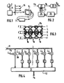
- La figure 1 illustre un système dans lequel l'invention est utilisée.Figure 1 illustrates a system in which the invention is used.
- La figure 2 est un schéma général d'un égaliseur.Figure 2 is a general diagram of an equalizer.
- La figure 3 représente un "diagramme de l'oeil".FIG. 3 represents a "diagram of the eye".
- La figure 4 est un schéma de filtre transversal utilisable dans le dispositif selon l'invention.FIG. 4 is a diagram of a transverse filter usable in the device according to the invention.
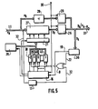
- La figure 5 est un schéma synoptique d'un dispositif d'égalisation complet selon l'invention.Figure 5 is a block diagram of a complete equalization device according to the invention.
Le système de la figure 1 est décrit à l'aide de signaux numériques codés en duobinaire, mais il est évident que l'invention est applicable aussi avec n'importe quel signal codé à plusieurs niveaux. Le signal D2-MAC/paquet reçu sur une antenne 2 est retransmis en modulation d'amplitude (modulation réalisée dans un centre de distribution 4) par un réseau de distribution par câble 14, vers un ou plusieurs téléviseurs dont un est représenté en 5. On utilise une modulation d'amplitude à bande latérale réduite qui offre l'avantage d'occuper moins de place, pour la même bande passante du signal modulant, que la modulation d'amplitude à double bande. Malheureusement, elle peut faire apparaître de l'interférence intersymbole si certains paramètres de la chaîne de transmission et de la démodulation ne respectent pas les principes théoriques.The system of Figure 1 is described using digital signals encoded in duobinary, but it is obvious that the invention is applicable also with any signal encoded on several levels. The D2-MAC / packet signal received on an
Pour le type de décodage envisagé ici, le signal D2-MAC/paquet est récupéré en bande de base sur la prise péritélévision du récepteur 5 à modulation d'amplitude et à bande latérale réduite (sortie dite vidéocomposite). Les signaux sont traités, pour y être décodés, dans l'élément 7 et les signaux d'image décodés, avec les signaux de son et les signaux de synchronisation sont renvoyés sur les bornes de la susdite prise de péritélévision. Le signal à corriger par l'égaliseur de l'invention est la partie duobinaire du multiplex temporel du signal D2-MAC/paquet. L'égaliseur est donc situé dans l'élément 7 en amont du circuit de décodage des données duobinaires; il est précédé d'un convertisseur analogique/numérique.For the type of decoding envisaged here, the D2-MAC / packet signal is recovered in baseband on the scart socket of
Sur le schéma du dispositif de correction de la figure 2, le signal d'entrée Xk (k est l'indice temporel de l'échantillon) est amené à un filtre numérique transversal 27. Le signal filtré yk qui en sort est amené à un comparateur à seuils 33 dans lequel le signal yk est comparé à deux seuils L placés à mi-amplitude de chacune des polarités du "diagramme de l'oeil" du signal reçu (fig 3), et le résultat de la comparaison permet de décider de la valeur normalisée (basse, nulle, haute) à attribuer au signal. Le signal "décidé" âk est le signal utile. Il est amené à un élément 34 qui calcule l'erreur, appelée ek, pour chaque échantillon. Cette erreur est la différence entre le signal "décidé" qui a une amplitude normalisée, et le signal filtré yk. L'erreur ek est fournie à un automate 35. Ce dernier adapte les coefficients du filtre dans le but de diminuer l'erreur quadratique moyenne. Il fournit au filtre les N coefficients c; adaptés.On the diagram of the correction device of FIG. 2, the input signal Xk (k is the time index of the sample) is brought to a transverse
Plusieurs types d'application d'un tel schéma existent pour réaliser un filtrage adaptatif au sens général, et plus particulièrement un filtrage auto-adaptatif, ou une annulation d'écho.Several types of application of such a scheme exist for carrying out adaptive filtering in the general sense, and more particularly self-adaptive filtering, or echo cancellation.
Pour supprimer l'interférence intersymbole, l'erreur quadratique moyenne entre le symbole "décidé" et le symbole réellement émis doit devenir minimale.To remove intersymbol interference, the mean square error between the "decided" symbol and the symbol actually issued must become minimal.
Dans un filtrage adaptatif, la séquence de symboles est connue et le récepteur dispose de la séquence, qui est comparée au signal décidé : il n'y a pas d'estimation à faire sur le signal reçu. Ce dispositif fonctionne sur de fortes distorsions, mais la synchronisation est délicate à réaliser.In an adaptive filtering, the sequence of symbols is known and the receiver has the sequence, which is compared with the decided signal: there is no estimation to be made on the received signal. This device works on strong distortions, but synchronization is difficult to achieve.
Dans un filtrage auto-adaptatif, le signal reçu est estimé. Cette estimation sert de signal de référence. Ce dispositif fonctionne sur toute information. Il h'y a pas de mémorisation de séquence. Habituellement, les algorithmes correspondants prévoient une phase d'apprentissage.In auto-adaptive filtering, the received signal is estimated. This estimate serves as a reference signal. This device works on any information. There is no sequence memorization. Usually, the corresponding algorithms provide for a learning phase.
Dans le cas d'un annuleur d'écho, il est nécessaire que le perturbateur soit connu: il est soustrait du signal reçu pour obtenir le signal émis. Un tel dispositif est réservé aux réseaux bi-directionnels de télécommunication.In the case of an echo canceller, it is necessary that the disturber is known: it is subtracted from the received signal to obtain the transmitted signal. Such a device is reserved for two-way telecommunications networks.
Dans la présente application, le perturbateur est inconnu; le troisième cas est donc exclu. Le premier cas nécessite d'avoir en permanence la mémorisation des informations de la séquence dans le récepteur. C'est donc le filtrage auto-adaptatif qui est ici le plus approprié. En outre, le présent système de transmission n'introduit pas de fortes distorsions, et la phase d'apprentissage n'est même pas nécesssaire.In the present application, the disruptor is unknown; the third case is therefore excluded. The first case requires permanent storage of the sequence information in the receiver. It is therefore self-adaptive filtering that is most appropriate here. Furthermore, the present transmission system does not introduce large distortions, and the learning phase is not even necessary.
Pour le processus d'autoadaptation, deux critères principaux d'optimisation peuvent être utilisés, à savoir : ou bien obtenir le minimum de la distorsion maximale, ou bien obtenir le minimum de l'erreur quadratique moyenne.For the self-adaptation process, two main optimization criteria can be used, namely: either obtain the minimum of the maximum distortion, or obtain the minimum of the mean square error.
De nombreux algorithmes existent pour répondre à ces critères. Les plus utilisés sont :
- - le forçage à zéro utilisé pour le minimum de la distorsion maximale
- - l'algorithme du gradient stochastique pour la minimisation de l'erreur quadratique moyenne.
De complexité équivalente, l'algorithme du gradient présente de meilleures performances: c'est cet algorithme qui a été choisi.
- - the forcing at zero used for the minimum of the maximum distortion
- - the algorithm of the stochastic gradient for the minimization of the mean square error.
Of equivalent complexity, the gradient algorithm presents better performances: it is this algorithm which was chosen.
Soit un filtre transversal non récursif à N coefficient C0,...CN-1; les données d'entrée, ainsi que les coefficients peuvent se mettre sous la forme :

-
peut s'écrire:

- où CT désigne le vecteur transposé de C.where C T denotes the transposed vector of C.
-
L'erreur est représentée par l'écart entre vk et ak :

-
Il s'agit de minimiser l'erreur quadratique moyenne J(C):

- (E est l'espérance mathématique)(E is the mathematical expectation)
-
qui représente une moyenne d'ensemble, proche de la moyenne temporelle :

-
Lorsque le filtre s'est stabilisé en régime permanent, l'équation (1) peut s'écrire encore :
- J(C) = CT.G.C. - 2CT.V + a2
- avec:
- a 2 = E (|ak|2)
- G = E (Xk.Xk T)
- V = E (Xk.ak)
- Le gradient de J(c) par rapport au vecteur C est donné par:
- ∂J/∂C = 2 (GC - V)
- Le vecteur optimal est défini lorsque le gradient est nul,
- donc : Copt = G-1.V
- On peut montrer que la matrice G est non singulière et que le vecteur Copt est unique.
- Pour converger vers Copt, l'algorithme du gradient déterministe utilise un procédé récursif pour modifier le filtre après chaque estimation :
- C(k+1) = C(k)-α.E(ekXk) α est une constante positive, qu'on nomme incrément de l'algorithme.\
- L'égaliseur fournit à l'organe de décision un échantillon yk représentant la meilleure estimation du symbole émis au sens de l'erreur quadratique moyenne minimale. La valeur délivrée par l'organe de décision est notée âk. Comme on ne dispose pas de la vraie valeur de ak, mais seulement de âk, c'est cette dernière valeur qui est utilisée en pratique pour réaliser l'algorithme.
- J (C) = C T .GC - 2C T. V + a 2
- with:
- a 2 = E (| a k | 2 )
- G = E (X k .X k T )
- V = E (X k .a k )
- The gradient of J (c) with respect to the vector C is given by:
- ∂J / ∂C = 2 (GC - V)
- The optimal vector is defined when the gradient is zero,
- therefore: C opt = G -1 .V
- We can show that the matrix G is non-singular and that the vector C opt is unique.
- To converge to C opt , the deterministic gradient algorithm uses a recursive process to modify the filter after each estimate:
- C (k + 1) = C (k) -α.E (e k X k ) α is a positive constant, which is called increment of the algorithm. \
- The equalizer provides the decision-making body with a sample y k representing the best estimate of the symbol emitted in the sense of the minimum mean square error. The value issued by the decision-making body is noted at k . As we do not have the true value of a k , but only of â k , it is this last value which is used in practice to carry out the algorithm.
En pratique, le calcul de E(ekXk) qui fait intervenir une espérance mathématique s'avère délicat; si la moyenne d'ensemble (1) se rapproche de la moyenne temporelle (2), donc si k est grand, l'estimation du gradient donnée par la valeur instantanée ek.xk est possible et les coefficients sont adaptés par la relation :![]()
![]()
Le procédé comporte deux phases :
- - la phase de filtrage proprement dite, à l'issue de laquelle on obtient une erreur d'estimation ek liée à l'état actuel C du filtre.
- - la phase d'adaptation contrôlée par ek, par xk, ainsi que par l'incrément α.
- - the actual filtering phase, at the end of which an estimation error e k is obtained linked to the current state C of the filter.
- - the adaptation phase controlled by e k , by x k , as well as by the increment α.
Les avantages de cet algorithme sont les suivants :
- - il y a peu de calculs (2N multiplications, N additions pour le filtrage, comme pour l'adaptation), donc la réalisation n'est pas complexe.
- - des versions simplifiées de cet algorithme peuvent encore réduire le coût du système (version "signe" à pas a constant).
- - there are few calculations (2N multiplications, N additions for filtering, as for the adaptation), therefore the realization is not complex.
- - simplified versions of this algorithm can further reduce the cost of the system ("sign" version with constant pitch).
C'est ainsi qu'on a choisi içi une version simplifiée de l'équation (3) :![]()
![]()
La réalisation de cette équation est possible en utilisant des "OU exclusif" pour la multiplication des deux signes.The realization of this equation is possible using "exclusive OR" for the multiplication of the two signs.
Les problèmes dûs au fait qu'on ne dispose que d'estimations de l'erreur et ceux dûs aux simplifications peuvent être évités en choisissant un pas a assurant un compromis entre la finesse de convergence (valeur de l'erreur quadratique moyenne résiduelle) et la vitesse de convergence. Dans la présente application, la vitesse de convergence n'a pas une grande importance, et il suffit de choisir un pas a assez petit pour assurer la convergence. Néanmoins, étant donné que l'égaliseur est destiné à équiper du matériel de type "grand public", il ne faut pas non plus opter pour un pas a trop petit, car la quantification des coefficients du filtre (c'est-à-dire le nombre de valeurs discrètes différentes qu'ils peuvent prendre) est directement égale à l'inverse du pas, et le coût des multiplications croît, quand a diminue.The problems due to the fact that only error estimates are available and those due to simplifications can be avoided by choosing a step a ensuring a compromise between the fineness of convergence (value of the residual mean square error) and the speed of convergence. In the present application, the speed of convergence is not of great importance, and it suffices to choose a step a small enough to ensure convergence. However, since the equalizer is intended to equip equipment of the "general public" type, it is also not necessary to opt for a step that is too small, since the quantification of the coefficients of the filter (that is to say the number of different discrete values they can take) is directly equal to the inverse of the step, and the cost of multiplication increases when a decreases.
Les essais ont montré qu'un pas α≦1/27≃ 0,008, pour un filtre à huit coefficients, assurait la convergence et donnait des résultats suffisants. Le filtre auto-adaptatif préféré a les caractéristiques suivantes :
- - c'est un filtre transversal ou linéaire non récursif à huit coefficients répartis en C-2,C-1,C0,C1,C2,C3,C4,C5; Co est le coefficient principal, C-2 et C-1 servent à corriger les perturbations de démodulation et Ci à Cs servent à corriger ces mêmes perturbations ainsi que les échos dont le retard est de 50 à 500ns.
- - il est auto-adaptable sur le critère de l'erreur quadratique moyenne minimale et à l'aide de l'algorithme du gradient déterministe signé.
- - le pas d'incrémentation est a ≃ 0,008 et la quantification des coefficients est de 8 bits y compris le signe. Sur le schéma de filtre numérique transversal de la figure 4 les signaux sont indiqués avec les mêmes références que dans l'exposé théorique ci-dessus. Le signal xk à l'entrée 11 du filtre est amené à un groupe de multiplieurs 38 en parallèle (les multiplieurs sont tous identiques et pour alléger la figure, seule la référence du multiplieur le plus à gauche est indiquée). Chacun d'eux reçoit un coefficient multiplicateur respectivement C-2,C-i ,Co,C, ,C2,C3, C4,C5 (de la gauche vers la droite) en provenance de l'élément 35 de la figure 2. Le signal sortant de chaque multiplieur est amené à
un sommateur 12, à chaque fois à travers un circuit retardateur T,2T,3T,....7T, respectivement de la gauche vers la droite (les signes T,2T,3T,...7T représentent à la fois les références des éléments et les durées de retardement). Le sommateur 12 fournit en sortie le signal yk.
- - it is a non-recursive transverse or linear filter with eight coefficients distributed in C -2 , C -1 , C 0 , C 1 , C 2 , C 3 , C 4 , C 5 ; Co is the main coefficient, C- 2 and C- 1 are used to correct demodulation disturbances and Ci to Cs are used to correct these same disturbances as well as echoes whose delay is 50 to 500ns.
- - it is self-adaptable on the criterion of minimum mean square error and using the signed deterministic gradient algorithm.
- - the incrementation step is at ≃ 0.008 and the quantization of the coefficients is 8 bits including the sign. On the diagram of transverse digital filter of figure 4 the signals are indicated with the same references as in the theoretical presentation above. The signal x k at the
input 11 of the filter is brought to a group ofmultipliers 38 in parallel (the multipliers are all identical and to simplify the figure, only the reference of the leftmost multiplier is indicated). Each of them receives a multiplying coefficient respectively C- 2 , Ci, Co, C,, C 2 , C 3 , C 4 , C 5 (from left to right) from element 35 in Figure 2 The outgoing signal of each multiplier is brought to asummator 12, each time through a delay circuit T, 2T, 3T, .... 7T, respectively from left to right (the signs T, 2T, 3T, ... 7T represent both the references of the elements and the delay times). Theadder 12 outputs the signal y k .
Dans le dispositif complet représenté par la figure 5, le signal duobinaire est amené sous forme numérique sur un bus 11 à huit fils. Le signal xk est exprimé, non pas en binaire naturel, mais en binaire signé (complément à deux): le bus 11 comporte donc sept fils de valeur et un fil de signe. Le signal xk est amené au filtre numérique 27 qui est constitué selon le schéma de la figure 4. Son signal de sortie yk traverse un élément 26 qui est un registre commutateur. Le signal d'entrée xk est également amené à un élément 28 de retardement destiné à fournir un signal identique au signal d'entrée mais retardé du nombre R de périodes d'horloge voulu pour être en synchronisme avec le signal issu du filtre 27. Ce signal retardé (Xk.R) est fourni à un registre 29. Le signal de sortie 31 est prélevé à volonté dans le registre 29 (xk.R non filtré) ou dans le registre 26 (yk filtré). Ce signal est amené à un élément 36 qui détermine directement le signe de l'erreur sgn(ek). Il n'utilise pas de comparateur à seuils à proprement parler (le commparateur 33 avait été mentionné plus haut pour simplifier les explications), mais contient une mémoire morte (PROM) dont le rôle sera expliqué maintenant.Pour une valeur déterminée du signal yk, il est facile de déterminer à la fois âk et ek. Pour illustrer cela, une valeur yk est indiquée à titre d'exemple sur la figure 3. Sa valeur est supérieure au seuil L le plus haut: donc âk vaut 1. Comme la valeur yk est supérieure à âk, le signe de l'erreur est positif. Pour n'importe quelle valeur de yk les mêmes déductions simples peuvent être faites. En pratique, la valeur de yk est introduite dans la mémoire PROM en tant qu'adresse, et à chaque adresse a été inscrite à l'avance la valeur sgn(ek) qui correspond. Cette valeur est délivrée sur un fil 22. Ce fil 22 ainsi que le fil de signe 32 portant le signe de xk (et qui est prélevé sur le bus 11) sont connectés aux entrées d'une porte OU exclusif 9. Le fil 32 traverse en outre un élément de retardement 17, de façon que le signe amené à la porte 9 devienne celui de l'échantillon xk.,, au lieu de celui de l'échantillon xk. En choisissant par exemple l'état UN pour désigner le signe plus et l'état ZERO pour désigner le signe moins, il est aisé de vérifier, en passant en revue tous les cas possibles (tableau de vérité), que la porte 9 fournit en sortie le signal: -sgn(ek).sgn(xk.;).In the complete device represented by FIG. 5, the duobinary signal is brought in digital form on an eight-
Pour le traitement des 8 coefficients du filtre, il faut une configuration qui permette de les mémoriser et de les adapter: on utilise dans le dispositif d'Adam LENDER déjà citée un stockage série, à l'aide d'une mémoire rapide, ou de registres à décalage. Bien que cette solution offre un gain de place, elle permet difficilement de réaliser la lecture, l'adaptation et l'écriture en un seul coup d'horloge pour chaque coefficient, ce qui ralentit le temps d'adaptation et exige des temps d'accès mémoire très courts (<25ns). C'est une configuration différente avec stockage parallèle qui a été choisie: pour réaliser la multiplication par a, chaque coefficient du filtre est représenté respectivement par le chiffre de comptage d'un compteur 38,39,40,....,45, chiffre qui est mémorisé par chaque compteur et transféré au filtre 27 via un registre 21. Les compteurs qui correspondent aux coefficients à ajuster comptent en binaire signé avec une capacité de ∓27, soit +128, c'est à dire que leur capacité exprimée en bits est égale au nombre de bits de quantification des coefficients du filtre. Ainsi l'incrémentation ou la décrémentation d'une unité représente une variation d'un cent vingt huitième de la valeur maximale, ce qui revient donc à ajouter ou retrancher a. En appliquant une telle variation dans le sens correspondant au produit des signes de xk.; et ek, on réalise l'opération:
-α.sgn(ek). sgn(xk.;)
de l'équation 4. A cet effet le signal de sortie de la porte 9 est amené aux compteurs pour commander le comptage ou le décomptage selon que ledit signal de sortie est à UN ou à ZERO.For the treatment of the 8 filter coefficients, a configuration is required which allows them to be memorized and adapted: in the Adam LENDER device already mentioned, a serial storage is used, using a fast memory, or shift registers. Although this solution saves space, it makes it difficult to perform reading, adaptation and writing in a single clock for each coefficient, which slows the adaptation time and requires time to very short memory access (<25ns). It was a different configuration with parallel storage which was chosen: to carry out the multiplication by a, each coefficient of the filter is represented respectively by the counting figure of a
-α.sgn (ek). sgn (x k .;)
of equation 4. For this purpose the output signal from gate 9 is brought to the counters to control the counting or counting down depending on whether said output signal is at ONE or at ZERO.
Certains décodeurs de signal D2-MAC/paquet disponibles dans le commerce travaillent avec une fréquence d'échantillons de 20,25 Mhz alors que le rythme de bits de la période duobinaire en D2-MAC/paquet est de 10,125 Mhz: lorsqu'on utilise un signal fourni par un tel décodeur, on n'en traite qu'un échantillon sur deux dans le présent dispositif. A cet effet, un signal d'horloge H à 10,125 Mhz, en phase avec les ventres du diagramme de l'oeil (figure 3), qui est engendré à partir du susdit décodeur, est amené à tous les éléments du présent dispositif et notamment à l'élément 36 pour y déclencher la lecture de sgn-(ek). Il est amené aussi à un organe de gestion 16 qui est relié aux compteurs et au registre 21. Cet organe sert notamment à désigner le compteur qui doit fonctionner à un instant donné, au moyen de l'entrée d'autorisation ("enable") de ce dernier. En effet les compteurs fonctionnent chacun à leur tour au rythme de l'horloge, de façon à ce que la valeur de i dans xk.; soit à chaque fois la bonne. Après huit périodes d'horloge, les valeurs de comptage sont toutes établies et l'organe 16 déclenche alors la fourniture des valeurs des coefficients par le registre 21 au filtre 27. A ce moment, l'organe de gestion 16 attend encore huit périodes d'horloge, afin que l'effet de la modification des coefficients soit complet en sortie du filtre puis en sortie de l'élément 36 (le temps de transit total est d'environ huit périodes d'horloge), et il déclenche alors un nouveau cycle d'autoadaptation des coefficients, le cas échéant.Some commercially available D2-MAC / packet signal decoders work with a sample rate of 20.25 Mhz while the bit rate of the duobinary period in D2-MAC / packet is 10.125 Mhz: when using a signal supplied by such a decoder, only one out of two samples is processed in this device. To this end, a clock signal H at 10.125 Mhz, in phase with the bellies of the eye diagram (FIG. 3), which is generated from the above-mentioned decoder, is supplied to all the elements of this device and in particular to element 36 to trigger the reading of sgn- (e k ). It is also brought to a
L'ensemble des éléments ou organes 16,38-45,21 constitue ainsi un automate pour réaliser le processus d'autoadaptation des coefficients du filtre.All the elements or
Sur la figure 3 sont indiquées des fenêtres F qui constituent un ensemble composé de trois fenêtres F, l'une encadrant le niveau normal d'un échantillon zéro, une autre encadrant le niveau normal d'un échantillon haut (1), et la troisième encadrant le niveau normal d'un échantillon bas (-1). Il est clair que pour chaque valeur de yk, le fait qu'elle soit ou non comprise dans une des fenêtres F ne dépend que de ladite valeur de yk. Ainsi que cela a été expliqué plus haut, l'élément 36 contient dans une mémoire PROM, pour chaque adresse correspondant à une valeur de yk, le signe de ek: en plus, un code est enregistré à chaque adresse indiquant si la valeur de yk est comprise dans une des fenêtres de l'ensemble de fenêtres F. L'élément 36 est ainsi un élément de décision qui fournit ledit code via un fil 19 à l'organe 16, de façon que ce dernier stoppe l'incrémentation des compteurs, c'est à dire l'autoadaptation des coefficients, lorsqu'une valeur de yk a été trouvée dans une des fenêtres. Une seule valeur de yk trouvée dans une des fenêtres suffit pour provoquer l'arrêt du processus, qui est ensuite maintenu arrêté jusqu'à ce qu'une valeur de yk soit à nouveau trouvée en dehors des fenêtres.In FIG. 3 are shown windows F which constitute a set composed of three windows F, one framing the normal level of a zero sample, another framing the normal level of a high sample (1), and the third framing the normal level of a low sample (-1). It is clear that for each value of y k , whether or not it is included in one of the windows F depends only on said value of y k . As explained above, element 36 contains in a PROM memory, for each address corresponding to a value of y k , the sign of e k : in addition, a code is recorded at each address indicating whether the value of y k is included in one of the windows of the set of windows F. The element 36 is thus a decision element which supplies said code via a
Par mesure de sécurité le coefficient principal du filtre est exclu du processus d'autoadaptation et maintenu à UN en permanence. Afin de diminuer l'erreur quadratique moyenne résiduelle en sortie, sans compliquer la gestion des coefficients, on peut avantageusement attribuer une dynamique deux fois plus forte, c'est à dire neuf bits, au coefficient principal, tout en laissant à huit bits la dynamique des coefficients latéraux; ceci est réalisable si l'amplitude de variation de ces derniers n'est pas supérieure à la moitié de l'amplitude du coefficient principal. Pour le type d'écho envisagé ici, cette hypothèse est réaliste.For safety reasons, the main filter coefficient is excluded from the self-adaptation process and kept at ONE permanently. In order to reduce the residual mean square error at output, without complicating the management of the coefficients, it is advantageous to assign a dynamic which is twice as strong, that is to say nine bits, to the main coefficient, while leaving the dynamic range at eight bits. coefficients lateral; this is achievable if the amplitude of variation of the latter is not greater than half the amplitude of the main coefficient. For the type of echo considered here, this assumption is realistic.
Le filtre auto-adaptatif doit se comporter au départ, et au moins jusqu'à ce que la synchronisation de l'horloge ait été établie par le décodeur de signaux D2-MAC/paquet, comme un filtre passe-tout. Après que cette synchronisation ait été établie, un signal correspondant à la durée de la salve duobinaire (10,5 /J.S) est introduit sur une entrée 30, pour être fourni aux registres 29, 26 et à l'organe de gestion 16. A partir de ce signal, l'organe 16 active le processus d'autoadaptation pendant cette période (10,5 /J.S), puis l'arrête pendant le reste de la ligne de télévision (53,5 u.s). Le signal 30 est aussi amené aux registres 26 et 29, pour mettre la sortie de l'un en état de haute impédance pendant que l'on utilise la sortie de l'autre et vice versa, de façon à choisir le signal filtré pendant la période de signal duobinaire et le signal non filtré pendant le reste de la ligne de télévision. Pendant ce reste de ligne on utilise un signal non filtré, car l'échantillonnage y est fait à 20,25 Mhz, alors que le fonctionnement du filtre est prévu à 10,125 Mhz, pour des raisons théoriques; moyennant quelques modifications, il pourrait néanmoins être envisagé de filtrer un échantillon sur deux des composantes MAC pendant ce reste de ligne, en laissant par conséquent alors le filtre toujours en service.The auto-adaptive filter must behave at the start, and at least until the clock synchronization has been established by the D2-MAC / packet signal decoder, like an all-pass filter. After this synchronization has been established, a signal corresponding to the duration of the duobinary burst (10.5 / JS) is introduced on an
Lors de l'initialisation de l'égaliseur, tous les coefficients ont la valeur zéro dans les compteurs. Bien que le coefficient principal du filtre soit maintenu à UN en permanence, avec certains types de filtres numériques il est néanmoins nécessaire de l'initialiser. A cet effet, l'organe 16 de gestion est relié à un élément 20 qui, lors de l'initialisation, transfère la valeur UN depuis un registre vers le compteur qui correspond au coefficient principal. Avec d'autres types de filtre, on pourrait cabler définitivement à UN le coefficient principal.When the equalizer is initialized, all the coefficients have a value of zero in the counters. Although the main filter coefficient is kept at ONE permanently, with certain types of digital filters it is nevertheless necessary to initialize it. To this end, the
Pour permettre un fonctionnement correct de ce filtre auto-adaptatif, il est utile de prévoir un circuit capable de détecter les coupures de l'alimentation, tels que ceux couramment utilisés dans les téléviseurs avec microprocesseurs, de façon à réinitialiser le processus d'auto-adaptation après une telle coupure.To allow this auto-adaptive filter to work properly, it is useful to provide a circuit capable of detecting power outages, such as those commonly used in televisions with microprocessors, so as to reset the auto-process. adaptation after such a cut.
Le présent dispositif pourrait aussi être utilisé avec des signaux de type DMAC ou à haute définition, moyennant toutefois quelques modifications.The present device could also be used with DMAC or high definition signals, however with some modifications.
Claims (14)
Applications Claiming Priority (2)
| Application Number | Priority Date | Filing Date | Title |
|---|---|---|---|
| FR8908797A FR2649273B1 (en) | 1989-06-30 | 1989-06-30 | SELF-ADAPTIVE EQUALIZATION DEVICE FOR DUOBINALLY CODED DIGITAL SAMPLES |
| FR8908797 | 1989-06-30 |
Publications (1)
| Publication Number | Publication Date |
|---|---|
| EP0405679A1 true EP0405679A1 (en) | 1991-01-02 |
Family
ID=9383326
Family Applications (1)
| Application Number | Title | Priority Date | Filing Date |
|---|---|---|---|
| EP90201663A Ceased EP0405679A1 (en) | 1989-06-30 | 1990-06-25 | Autoadaptive equalization device for duobinary coded digital samples |
Country Status (3)
| Country | Link |
|---|---|
| EP (1) | EP0405679A1 (en) |
| JP (1) | JPH03101515A (en) |
| FR (1) | FR2649273B1 (en) |
Cited By (1)
| Publication number | Priority date | Publication date | Assignee | Title |
|---|---|---|---|---|
| EP0923204A2 (en) * | 1997-12-11 | 1999-06-16 | Alcatel | Optical receiver for receiving digital transmitted data |
Families Citing this family (1)
| Publication number | Priority date | Publication date | Assignee | Title |
|---|---|---|---|---|
| US4985254A (en) * | 1987-11-06 | 1991-01-15 | Nippon Zoki Pharmaceutical Co., Ltd. | Method of treating ischemic diseases |
Citations (2)
| Publication number | Priority date | Publication date | Assignee | Title |
|---|---|---|---|---|
| EP0169093A1 (en) * | 1984-06-04 | 1986-01-22 | ETAT FRANCAIS repr. par le Secrétaire d'Etat aux Postes et Télécomm. et à la Télédiffusion (CENT. NAT. D'ETUDES DES TELECOMM.) | Receiver for time division multiplexed television transmission comprising a frequency demodulator |
| EP0308776A2 (en) * | 1987-09-25 | 1989-03-29 | Nippon Hoso Kyokai | Decoding equalizer |
-
1989
- 1989-06-30 FR FR8908797A patent/FR2649273B1/en not_active Expired - Fee Related
-
1990
- 1990-06-25 EP EP90201663A patent/EP0405679A1/en not_active Ceased
- 1990-06-30 JP JP2171386A patent/JPH03101515A/en active Pending
Patent Citations (2)
| Publication number | Priority date | Publication date | Assignee | Title |
|---|---|---|---|---|
| EP0169093A1 (en) * | 1984-06-04 | 1986-01-22 | ETAT FRANCAIS repr. par le Secrétaire d'Etat aux Postes et Télécomm. et à la Télédiffusion (CENT. NAT. D'ETUDES DES TELECOMM.) | Receiver for time division multiplexed television transmission comprising a frequency demodulator |
| EP0308776A2 (en) * | 1987-09-25 | 1989-03-29 | Nippon Hoso Kyokai | Decoding equalizer |
Non-Patent Citations (1)
| Title |
|---|
| IEEE TRANSACTIONS ON COMMUNICATION TECHNOLOGY * |
Cited By (3)
| Publication number | Priority date | Publication date | Assignee | Title |
|---|---|---|---|---|
| EP0923204A2 (en) * | 1997-12-11 | 1999-06-16 | Alcatel | Optical receiver for receiving digital transmitted data |
| EP0923204A3 (en) * | 1997-12-11 | 2000-12-06 | Alcatel | Optical receiver for receiving digital transmitted data |
| US6295152B1 (en) | 1997-12-11 | 2001-09-25 | Alcatel | Optical receiver for receiving digitally transmitted data |
Also Published As
| Publication number | Publication date |
|---|---|
| FR2649273A1 (en) | 1991-01-04 |
| FR2649273B1 (en) | 1991-09-13 |
| JPH03101515A (en) | 1991-04-26 |
Similar Documents
| Publication | Publication Date | Title |
|---|---|---|
| CA1173965A (en) | Method and device for detecting the training sequence of a self-adaptive equalizer | |
| FR2623669A1 (en) | EQUALIZATION APPARATUS AND METHOD FOR DATA TRANSMISSION | |
| FR2602944A1 (en) | Subscriber unit for wireless digital telephone; modem and diverse devices (frequency synthesizer etc.) for this unit | |
| FR2566604A1 (en) | RECEIVER OF RECORDED DATA | |
| FR2615675A1 (en) | METHOD FOR DEMODULATING MODULAR SIGNALS DIGITALLY AND DEVICE FOR IMPLEMENTING SUCH A METHOD | |
| EP0576359B1 (en) | Method and apparatus for decision feedback equalisation for the block transmission of information symbols | |
| FR2524742A1 (en) | METHOD FOR TRANSMITTING DUPLEX DATA ON A SWITCHED TELEPHONE CIRCUIT AND CORRESPONDING MODEM | |
| EP0409756B1 (en) | Data reception device with delayed equalizing and retroactive clock recovery | |
| FR2468258A1 (en) | PHASE NOISE CORRECTION CIRCUIT FOR A TRANSMISSION SYSTEM | |
| FR2679721A1 (en) | ADAPTIVE EQUALIZATION METHOD REDUCING INTERSYMBOL INTERFERENCE, AND CORRESPONDING RECEIVING DEVICE AND APPLICATION. | |
| CA1137177A (en) | Method for reducing phase noise at the receiving end of a data transmission link | |
| EP0405679A1 (en) | Autoadaptive equalization device for duobinary coded digital samples | |
| EP0169093A1 (en) | Receiver for time division multiplexed television transmission comprising a frequency demodulator | |
| EP3643024B1 (en) | Transmission and reception of a data stream | |
| EP0098198A2 (en) | Method and system for data rate compression of data transmitted between at least a transmitter and a receiver of television pictures | |
| FR2786965A1 (en) | SIGNAL CARRIER RECOVERY METHOD | |
| EP0127544A1 (en) | Echo canceller with an adaptive digital filter for a transmission system | |
| EP0434584B1 (en) | Linear and non-linear disturbances equalization device of a signal received through a disturbed transmission channel | |
| EP0348322B1 (en) | Method for the restoration of the continuous component of a dmac type signal, device therefor and use thereof | |
| EP0328461B1 (en) | Method of broadcasting a high-definition television programme, and receiver with equalizer for receiving such a programme | |
| EP1438815B1 (en) | Inter-symbol interference canceller | |
| EP0451754B1 (en) | Digital autoadaptive equalizer | |
| EP0296914B1 (en) | Method and television device with time division multiplex | |
| EP0411526A1 (en) | Device for the correction of transmission distorsions of a data signal according to transmission code violations | |
| FR2938988A1 (en) | METHOD FOR CONTINUOUS PHASE MULTISTATE MODULATION AND TRANSMITTER USING THE METHOD. |
Legal Events
| Date | Code | Title | Description |
|---|---|---|---|
| PUAI | Public reference made under article 153(3) epc to a published international application that has entered the european phase |
Free format text: ORIGINAL CODE: 0009012 |
|
| AK | Designated contracting states |
Kind code of ref document: A1 Designated state(s): DE FR GB IT |
|
| RAP1 | Party data changed (applicant data changed or rights of an application transferred) |
Owner name: N.V. PHILIPS' GLOEILAMPENFABRIEKEN Owner name: PHILIPS ELECTRONIQUE GRAND PUBLIC |
|
| 17P | Request for examination filed |
Effective date: 19910627 |
|
| 17Q | First examination report despatched |
Effective date: 19930609 |
|
| STAA | Information on the status of an ep patent application or granted ep patent |
Free format text: STATUS: THE APPLICATION HAS BEEN REFUSED |
|
| 18R | Application refused |
Effective date: 19941023 |