EP0405152B1 - Method for adjusting a spinning piezoelectric beam of a dual-axis angular rate sensor - Google Patents
Method for adjusting a spinning piezoelectric beam of a dual-axis angular rate sensor Download PDFInfo
- Publication number
- EP0405152B1 EP0405152B1 EP90110137A EP90110137A EP0405152B1 EP 0405152 B1 EP0405152 B1 EP 0405152B1 EP 90110137 A EP90110137 A EP 90110137A EP 90110137 A EP90110137 A EP 90110137A EP 0405152 B1 EP0405152 B1 EP 0405152B1
- Authority
- EP
- European Patent Office
- Prior art keywords
- piezoelectric
- piezoelectric sensors
- rotary shaft
- spinning
- angular rate
- Prior art date
- Legal status (The legal status is an assumption and is not a legal conclusion. Google has not performed a legal analysis and makes no representation as to the accuracy of the status listed.)
- Expired - Lifetime
Links
Images

Classifications
-
- G—PHYSICS
- G01—MEASURING; TESTING
- G01C—MEASURING DISTANCES, LEVELS OR BEARINGS; SURVEYING; NAVIGATION; GYROSCOPIC INSTRUMENTS; PHOTOGRAMMETRY OR VIDEOGRAMMETRY
- G01C25/00—Manufacturing, calibrating, cleaning, or repairing instruments or devices referred to in the other groups of this subclass
- G01C25/005—Manufacturing, calibrating, cleaning, or repairing instruments or devices referred to in the other groups of this subclass initial alignment, calibration or starting-up of inertial devices
-
- G—PHYSICS
- G01—MEASURING; TESTING
- G01C—MEASURING DISTANCES, LEVELS OR BEARINGS; SURVEYING; NAVIGATION; GYROSCOPIC INSTRUMENTS; PHOTOGRAMMETRY OR VIDEOGRAMMETRY
- G01C19/00—Gyroscopes; Turn-sensitive devices using vibrating masses; Turn-sensitive devices without moving masses; Measuring angular rate using gyroscopic effects
- G01C19/02—Rotary gyroscopes
Definitions
- the present invention relates to a method for adjusting a spinning piezoelectric beam of a dual-axis angular rate sensor which is employed for attitude control of navigable vehicles such as aircraft.
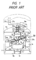
- Fig. 1 illustrates a conventional spinning beam type, dual-axis angular rate sensor.
- Both end plates 11a and 11b of a cylindrical case 11 have mounted thereon bearings 12 and 13, respectively, and a rotary shaft 21 of a spinning piezoelectric beam 20 passes through the bearings 12 and 13 and is held therebetween in a manner to be rotatable about the Z axis.
- Two parallel beam-shaped piezoelectric sensors 22a and 22b are affixed, by support washers 24, to the rotary shaft 21 at right angles thereto and symmetrically with respect thereto.
- the piezoelectric sensors 22a and 22b are produced, for example, by forming electrodes 25a and 25b on both sides of bimorph type piezoelectric crystal beams, and they are held perpendicular to the rotary shaft 21. Mounted on both sides of the piezoelectric sensors 22a and 22b at their free end portions are weights 23a and 23b for increasing the angular rate detecting sensitivity.
- the piezoelectric spinning beam 20 is driven at high speed by a motor stator 14 fixed in the case 11 and a motor rotor 15 fixedly mounted on the rotary shaft 21.
- the outputs of the piezoelectric sensors 22a and 22b, provided at the electrodes 25a and 25b, are led out via leads (not shown) extending through the rotary shaft 21, slip rings 24a, 24b and 24c, brushes 16a, 16b and 16c, and preamplifiers 31a and 31b.
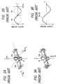
- the X and Y axes which lie in a plane containing the piezoelectric sensors 22a and 22b and perpendicular to the Z axis and perpendicularly intersect each other are defined as shown in Fig. 2A.
- ⁇ x shown as a vector indicated by the arrow in the X-axis direction
- Coriolis force acts on the piezoelectric sensors 22a and 22b spinning about the Z axis at an angular rate ⁇ z, by which the piezoelectric sensors 22a and 22b bend in opposite directions at opposite sides with respect to the Y axis as depicted in Fig. 2A.
- the piezoelectric sensors 22a and 22b yield sine-wave voltage signals x a and X b which have an amplitude proportional to the applied angular rate ⁇ x and are displaced 180° apart in phase as indicated by the solid line and the broken line in Figs. 2B. Also in the case where the case 11 of the angular rate sensor is rotated about the Y axis at an angular rate ⁇ y, the piezoelectric sensors 22a and 22b similarly create sine-wave voltage signals y a and y b which have an amplitude proportional to the angular rate ⁇ y and are displaced 180° apart in phase.
- the signals y a and Y b are phased 90° apart from the signals X a and x b , respectively.
- a vibrational acceleration ⁇ acts on the piezoelectric sensors 22a and 22b in the Z-axis direction
- the sensors 22a and 22b vibrate in the same phase as shown in Fig. 3A, yielding voltage signals z a and z b which are of the same magnitude proportional to the acceleration ⁇ and of the same sign as depicted in Fig. 3B.
- the prior art employs an arrangement in which another piezoelectric sensor is affixed to the rotary shaft for sensing linear acceleration perpendicular thereto and its output signal is added to that of the angular rate sensing piezoelectric sensor to correct the error signal (for example, JP-A-120914/86 and GB-A-2 167 562.
- the conventional angular rate sensor calls for the piezoelectric sensor for correction use and is adapted to permit adjustment of the angle at which the piezoelectric sensor is affixed to the rotary shaft; hence, the prior art is inevitably complex in structure.
- the electrodes of the piezoelectric sensors 22a and 22b each extend to the ends of support washers by which the sensor is affixed to the rotary shaft, and consequently, the outputs of the sensors 22a and 22b are affected by the stresses supporting them.
- a preload on each of the bearings 12 and 13 due to their misalignment differs with angular positions and causes a difference between the support stresses which act on the both piezoelectric sensors 22a and 22b through the rotary shaft 21, and the stress difference varies with the rotational stress.
- neutral axes of the two piezoelectric sensors at their respective bending portions are adjusted to be essentially parallel to a plane perpendicular to the rotary shaft
- the pendulum axes joining support points of the two piezoelectric sensors and the centers of gravity of weights at their free end portions are adjusted to be essentially parallel to the plane perpendicular to the rotary shaft.
- the adjustment of the neutral axes is done by grinding a proper one of four corners of each piezoelectric sensor at its bending portion in the cross-section thereof.
- the adjustment of the pendulum axes is made by properly grinding the pair of weights of each piezoelectric sensor.
- Fig. 4 illustrates a signal measuring circuit 30 and an exciting unit 40 of a device for adjusting the spinning piezoelectric beam according to the present invention.
- the exciting unit 40 has an exciting stand 41 and an attachment 42, and the exciting stand 41 can be vibrated in the Z-axis direction at a desired frequency and with a desired amplitude.
- the rotary shaft 21 of the spinning piezoelectric beam 20 is fixed at both ends to the attachment 42 which is mounted on the exciting stand 41 in such a manner that it is rotatable about a shaft 43.
- Detected voltage signals Sa and Sb from the two piezoelectric sensors 22a and 22b are output via rings 24a, 24b, 24c and brushes 16a, 16b, 16c as in the case of the angular rate sensor shown in Fig. 1, and the output signals are applied to preamplifiers 31a and 31B provided on the attachment 42 and then input into the signal measuring circuit 30.
- the input signals Sa and Sb are provided via filters 32a and 32b to variable gain amplifiers 33a and 33b, wherein they are adjusted in amplitude, thereafter being applied to variable phase shifters 34a and 34b for their phase adjustment.
- the outputs of the phase shifters 34a and 34b are provided to terminals 36a and 36b, respectively, and at the same time, they are applied to a differential amplifier 35, wherein a difference between the two signals is detected and from which the difference signal is provided to an output terminal 36d.
- the signals thus derived at the output terminals 36a, 36b and 36d are displayed on, for instance, a CRT though not shown.
- a description will be given of the method for adjusting the spinning piezoelectric beam 20.
- Step 1 First, the attachment 42 is fixed after being turned so that the rotary shaft 21 of the spinning piezoelectric beam 20 mounted on the attachment 42 is parallel to an excitation axis (W axis) as shown in Fig. 4. Then, a vibrational acceleration is applied by the exciting unit 40 in the direction of the rotary shaft 21 at a fixed frequency (200 Hz, for example) and with a fixed amplitude, the output signals Sa and Sb of the both piezoelectric sensors 22a and 22b are provided to the signal measuring circuit 30, and the gain of at least one of the variable gain amplifiers 33a and 33b and the phase shift amount of at least one of the phase shifters 34a and 34b are adjusted so that the level of the difference signal provided at the output terminal 36d becomes minimum.
- a vibrational acceleration is applied by the exciting unit 40 in the direction of the rotary shaft 21 at a fixed frequency (200 Hz, for example) and with a fixed amplitude
- the output signals Sa and Sb of the both piezoelectric sensors 22a and 22b are provided
- Step 2 Next, the attachment 42 is turned and fixed at such a position where the rotary shaft 21 perpendicularly crosses the excitation axis W, and the piezoelectric sensors 22a and 22b are turned into agreement with the V axis. Then, a vibrational acceleration of a fixed frequency (200 Hz, for example) and a fixed amplitude is applied by the exciting unit 40 in a direction perpendicular to both of the rotary shaft 21 and the piezoelectric sensors 22a and 22b lengthwise thereof, and the signal levels at the terminals 36a and 36b are observed.
- a fixed frequency 200 Hz, for example
- a proper one or ones of four corners C1 to C4 of bending portions Ba and Bb of the piezoelectric sensors 22a and 22b are ground so that the signal levels at the output terminals 36a and 36b become minimum.
- the grinding is stopped when the signal levels at the terminals 36a and 36b become lower than a predetermined voltage V1.
- the corners C1 to C4 of the bending portions Ba and Bb are further ground so that the output difference signal level at the terminal 36d becomes minimum, or in practice, lower than a predetermined voltage V2.
- the bending portions Ba and Bb are those within predetermined ranges from marginal edges of support washers 24 in the lengthwise direction of the piezoelectric sensors 22a and 22b, and when the piezoelectric sensors 22a and 22b are bent by acceleration or Coriolis acceleration, their curvature becomes largest near the above-mentioned portions.
- the range of grinding in the bending portions Ba and Bb may preferably be outside electrodes 25a and 25b as described later, and more preferably, they are each selected within 1.5 times larger than the thickness T of the piezoelectric sensor from the marginal edge of the support washers 24.
- the neutral axes Na and Nb are straight lines joining points in the beam which are free from both tensile stress and compressive stress in the bending portions Ba and Bb when the piezoelectric sensors 22a and 22b are bent.
- the piezoelectric sensor 22b is similarly ground for adjustment.
- the piezoelectric sensors 22a and 22b are alternately subjected to the above-mentioned grinding.
- Step 3 The attachment 42 is fixed at the same position as in Step 2 but the rotary shaft 21 is turned 90° so that the piezoelectric sensors 22a and 22b extend along the W axis.
- a vibrational acceleration of a fixed frequency and a fixed amplitude is applied by the exciting unit 40 along the lengthwise direction of the piezoelectric sensors 22a and 22b at right angles to the rotary shaft 21.
- the weights 23a and 23b of the piezoelectric sensors 22a and 22b are ground so that the output signal levels at the terminals 36a and 36b become minimum, or in practice, become lower than a predetermined voltage V3.
- the weights 23a and 23b are ground so that the output difference signal level at the terminal 36d becomes minimum, or in practice, becomes lower than a predetermined voltage V4.
- the pendulum axes Pa and Pb joining the support points of the piezoelectric sensors 22a and 22b and the centers of gravity of the weights 23a and 23b, respectively become parallel to the plane perpendicular to the rotary shaft 21, affording reduction of the error that is caused by the acceleration applied lengthwise of the piezoelectric sensors 22a and 22b.
- the pendulum axes Pa and Pb are straight lines joining support points which are the center points of the piezoelectric sensors 22a and 22b in their cross-section at the marginal edges of the support washers 24 and the centers of gravity of the pairs of weights 23a and 23b.
- the above-mentioned grinding takes place on the edge of one or both of the weights 23a and 23b as shown in Fig. 5, for example. Note that only those of the pairs of weights 23a and 23b mounted on both sides of the piezoelectric sensors 22a and 22b which are opposite from the direction of shifting their centers of gravity are ground.
- acceleration components of signals detected by the piezoelectric sensors 22a and 22b in the direction of the rotary shaft 21 are equal to each other, and hence they can be canceled, and acceleration components perpendicular to the rotary shaft 21 are all negligibly small.
- the afore-mentioned voltages V1 and V4 are predetermined in accordance with the measurement accuracy required of the dual-axis angular rate sensor.
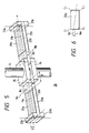
- Fig. 5 shows the principal part of an embodiment of the spinning piezoelectric beam 20.
- the electrodes 25a and 25b on both sides of each of the piezoelectric sensors 22a and 22b are each formed at a distance from the piezoelectric sensor supporting end, that is, the marginal edge of the support washer 24, i.e. at a position where the electrode will not be affected by the stress at the support portion.
- the spinning piezoelectric beam of the present invention is applicable as well to a conventional dual-axis angular rate/accelerometer which additionally includes a dual-axis acceleration sensing function by affixing an acceleration sensing piezoelectric sensor to the rotary shaft of the spinning beam type angular rate sensor.
- the spinning piezoelectric beam is adjusted so that the neutral axes and the pendulum axes of the both piezoelectric sensors are both parallel to the plane perpendicular to the rotary shaft, it is possible to eliminate an error component proportional to acceleration.
- the application of such an adjusted spinning piezoelectric beam to a dual-axis angular rate sensor precludes the necessity of using an acceleration sensing piezoelectric sensor for correcting an acceleration error, and hence permits simplification of the overall structure of the angular rate sensor.
- the above-said adjustment of the spinning piezoelectric beam enables removal of the error component resulting from acceleration, without the necessity of highly accurate machining of parts and highly accurate assembling thereof. Hence, the angular rate sensor can easily be manufactured at low cost.
Description
- The present invention relates to a method for adjusting a spinning piezoelectric beam of a dual-axis angular rate sensor which is employed for attitude control of navigable vehicles such as aircraft.
- Fig. 1 illustrates a conventional spinning beam type, dual-axis angular rate sensor. Both
end plates cylindrical case 11 have mounted thereonbearings rotary shaft 21 of a spinningpiezoelectric beam 20 passes through thebearings piezoelectric sensors support washers 24, to therotary shaft 21 at right angles thereto and symmetrically with respect thereto. Thepiezoelectric sensors electrodes rotary shaft 21. Mounted on both sides of thepiezoelectric sensors weights piezoelectric spinning beam 20 is driven at high speed by amotor stator 14 fixed in thecase 11 and amotor rotor 15 fixedly mounted on therotary shaft 21. The outputs of thepiezoelectric sensors electrodes rotary shaft 21,slip rings brushes preamplifiers - Now, the X and Y axes which lie in a plane containing the
piezoelectric sensors case 11 of the angular rate sensor is rotated about the X axis at an angular rate Ωx (shown as a vector indicated by the arrow in the X-axis direction), Coriolis force acts on thepiezoelectric sensors piezoelectric sensors piezoelectric sensors case 11 of the angular rate sensor is rotated about the Y axis at an angular rate Ωy, thepiezoelectric sensors piezoelectric sensors sensors piezoelectric sensors piezoelectric sensors 

- In practice, however, it is difficult to affix the
piezoelectric sensors rotary shaft 21 accurately at right angles thereto and in a correct attitude, because of limitations on machining and assembling accuracy of parts. Moreover, where the composite centers of gravity of theweights piezoelectric sensors piezoelectric sensors - Furthermore, in the conventional angular rate sensor the electrodes of the
piezoelectric sensors sensors bearings piezoelectric sensors rotary shaft 21, and the stress difference varies with the rotational stress. This introduces a difference between the outputs of thepiezoelectric sensors - It is therefore an object of the present invention to provide a spinning piezoelectric beam adjustment method which ensures the elimination of the acceleration signal component that introduces an error in the angular rate signal.
- This object is achieved with a method as claimed.
- According to present invention, neutral axes of the two piezoelectric sensors at their respective bending portions are adjusted to be essentially parallel to a plane perpendicular to the rotary shaft, and the pendulum axes joining support points of the two piezoelectric sensors and the centers of gravity of weights at their free end portions are adjusted to be essentially parallel to the plane perpendicular to the rotary shaft. The adjustment of the neutral axes is done by grinding a proper one of four corners of each piezoelectric sensor at its bending portion in the cross-section thereof. The adjustment of the pendulum axes is made by properly grinding the pair of weights of each piezoelectric sensor.
- Since the neutral axes and the pendulum axes of the both piezoelectric sensors are adjusted as mentioned above, their output signals responding to an acceleration in the direction of the rotary shaft agree with each other in their level and phase, and their output signals responding to an acceleration in an arbitrary direction perpendicular to the rotary shaft are very low in level and have the same level and phase. Accordingly, all acceleration components in the outputs of the both piezoelectric sensors can be canceled each other to such an extent as to be negligibly small.
-
- Fig. 1 is an exploded perspective view showing the internal construction of a conventional dual-axis angular rate sensor;
- Fig. 2A is a perspective view showing bends of both piezoelectric sensors;
- Fig. 2B shows output voltage waveforms of the two piezoelectric sensors depicted in Fig. 2A;
- Fig. 3A is a perspective view showing bends of the both piezoelectric sensors when a vibrational acceleration is applied to the dual-axis angular rate sensor;
- Fig. 3B shows output voltage waveforms of the two piezoelectric sensors in Fig. 3A;
- Fig. 4 is a system diagram illustrating an
exciting unit 40 and asignal measuring circuit 30 for adjusting a spinning piezoelectric beam according to the present invention; - Fig. 5 is a perspective view illustrating the principal part of an embodiment of the spinning piezoelectric beam according to the present invention;
- Fig. 6 is a sectional view taken on a line passing through the neutral axis of a bending portion of the piezoelectric sensor.
- Fig. 4 illustrates a
signal measuring circuit 30 and anexciting unit 40 of a device for adjusting the spinning piezoelectric beam according to the present invention. Theexciting unit 40 has anexciting stand 41 and anattachment 42, and theexciting stand 41 can be vibrated in the Z-axis direction at a desired frequency and with a desired amplitude. Therotary shaft 21 of the spinningpiezoelectric beam 20 is fixed at both ends to theattachment 42 which is mounted on theexciting stand 41 in such a manner that it is rotatable about a shaft 43. Detected voltage signals Sa and Sb from the twopiezoelectric sensors rings brushes preamplifiers 31a and 31B provided on theattachment 42 and then input into thesignal measuring circuit 30. - In the
signal measuring circuit 30 the input signals Sa and Sb are provided viafilters variable gain amplifiers variable phase shifters phase shifters terminals differential amplifier 35, wherein a difference between the two signals is detected and from which the difference signal is provided to anoutput terminal 36d. The signals thus derived at theoutput terminals piezoelectric beam 20. - Step 1: First, the
attachment 42 is fixed after being turned so that therotary shaft 21 of the spinningpiezoelectric beam 20 mounted on theattachment 42 is parallel to an excitation axis (W axis) as shown in Fig. 4. Then, a vibrational acceleration is applied by theexciting unit 40 in the direction of therotary shaft 21 at a fixed frequency (200 Hz, for example) and with a fixed amplitude, the output signals Sa and Sb of the bothpiezoelectric sensors signal measuring circuit 30, and the gain of at least one of thevariable gain amplifiers phase shifters output terminal 36d becomes minimum. - Step 2: Next, the
attachment 42 is turned and fixed at such a position where therotary shaft 21 perpendicularly crosses the excitation axis W, and thepiezoelectric sensors exciting unit 40 in a direction perpendicular to both of therotary shaft 21 and thepiezoelectric sensors terminals piezoelectric sensors piezoelectric sensor 22a being shown on an enlarged sectional view taken on the line passing through a neutral axis Na in Fig. 6) are ground so that the signal levels at theoutput terminals terminals rotary shaft 21. - As shown in Fig. 5, the bending portions Ba and Bb are those within predetermined ranges from marginal edges of
support washers 24 in the lengthwise direction of thepiezoelectric sensors piezoelectric sensors outside electrodes support washers 24. The neutral axes Na and Nb are straight lines joining points in the beam which are free from both tensile stress and compressive stress in the bending portions Ba and Bb when thepiezoelectric sensors - For instance, in the case where it is desired to slightly turn the neutral axis Na clockwise as indicated by Na′ in Fig. 6, one or both of the corners C₂ and C₄ on the side opposite from the direction of rotation are ground. In the case of slightly turning the neutral axis Na counterclockwise, one or both of the corners C₁ and C₃ on the side opposite from the direction of rotation are ground. If necessary, the
piezoelectric sensor 22b is similarly ground for adjustment. Alternatively, thepiezoelectric sensors piezoelectric sensors - Step 3: The
attachment 42 is fixed at the same position as in Step 2 but therotary shaft 21 is turned 90° so that thepiezoelectric sensors exciting unit 40 along the lengthwise direction of thepiezoelectric sensors rotary shaft 21. In this instance, theweights piezoelectric sensors terminals weights weights piezoelectric sensors weights rotary shaft 21, affording reduction of the error that is caused by the acceleration applied lengthwise of thepiezoelectric sensors - The pendulum axes Pa and Pb are straight lines joining support points which are the center points of the
piezoelectric sensors support washers 24 and the centers of gravity of the pairs ofweights weights weights piezoelectric sensors - Where an acceleration of an arbitrary direction is applied to a dual-axis angular rate sensor employing the spinning
piezoelectric beam 20 adjusted following Steps 2 and 3 mentioned above, acceleration components of signals detected by thepiezoelectric sensors rotary shaft 21 are equal to each other, and hence they can be canceled, and acceleration components perpendicular to therotary shaft 21 are all negligibly small. Incidentally, the afore-mentioned voltages V₁ and V₄ are predetermined in accordance with the measurement accuracy required of the dual-axis angular rate sensor. - Fig. 5 shows the principal part of an embodiment of the spinning
piezoelectric beam 20. Theelectrodes piezoelectric sensors support washer 24, i.e. at a position where the electrode will not be affected by the stress at the support portion. - According to the spinning
piezoelectric beam 20 of the above construction, even if the difference between the support stresses which act on the bothpiezoelectric sensors rotary shaft 21 varies owing to a misalignment of the spinning beam or acceleration, its influence does not ever appear in the outputs of thepiezoelectric sensors - The spinning piezoelectric beam of the present invention is applicable as well to a conventional dual-axis angular rate/accelerometer which additionally includes a dual-axis acceleration sensing function by affixing an acceleration sensing piezoelectric sensor to the rotary shaft of the spinning beam type angular rate sensor.
- As described above, according to the present invention, since the spinning piezoelectric beam is adjusted so that the neutral axes and the pendulum axes of the both piezoelectric sensors are both parallel to the plane perpendicular to the rotary shaft, it is possible to eliminate an error component proportional to acceleration. The application of such an adjusted spinning piezoelectric beam to a dual-axis angular rate sensor precludes the necessity of using an acceleration sensing piezoelectric sensor for correcting an acceleration error, and hence permits simplification of the overall structure of the angular rate sensor. Moreover, the above-said adjustment of the spinning piezoelectric beam enables removal of the error component resulting from acceleration, without the necessity of highly accurate machining of parts and highly accurate assembling thereof. Hence, the angular rate sensor can easily be manufactured at low cost.
Claims (4)
- A method for adjusting a spinning piezoelectric beam (20) in which two beam-shaped piezoelectric sensors (22a,22b) are affixed to a rotary shaft (21) at right angles thereto and symmetrically with respect thereto while being gripped by support washers (24) in parallel to each other and each of said piezoelectric sensors carries weights (23a,23b) at its free end, said method comprising:
a first step wherein said spinning piezoelectric beam is excited by an exciting unit in a direction perpendicular to said rotary shaft and to the lengthwise direction of said piezoelectric sensors, detected signals of said two piezoelectric sensors are measured by a signal measuring circuit (30), and a bending portion (Ba,Bb) of at least one of said two piezoelectric sensors is ground until the detected voltages of said two piezoelectric sensors measured by said signal measuring circuit each become smaller than a predetermined first value and until their difference becomes smaller than a predetermined second value; and
a second step wherein said spinning piezoelectric beam is excited by said exciting unit in the lengthwise direction of said piezoelectric sensors at right angles to said rotary shaft, and said weights of at least one of said two piezoelectric sensors are ground until the detected voltages of said two piezoelectric sensors measured by said signal measuring circuit each become smaller than a predetermined third value and until their difference becomes smaller than a predetermined fourth value. - The adjusting method of claim 1 further including, prior to said first and second steps, a step wherein said spinning piezoelectric beam (20) is excited by said exciting unit in the direction of said rotary shaft (21), and the amplitude and the phase of at least one of two signals measured by said signal measuring circuit (30) supplied with the detected voltages of said two piezoelectric sensors are adjusted to thereby adjust said signal measuring circuit so that the difference between said two signals becomes minimum.
- The adjusting method of claim 1 or 2, wherein the range of said bending portion (Ba,Bb) to be ground is between said support washers (24) and electrodes (25a,25b) of the corresponding one of said two piezoelectric sensors (22a,22b).
- The adjusting method of claim 3, wherein the range of said bending portion to be ground is a range of 1.5 times the thickness of said corresponding piezoelectric sensor from the marginal edge of each of said support washers.
Applications Claiming Priority (2)
| Application Number | Priority Date | Filing Date | Title |
|---|---|---|---|
| JP136657/89 | 1989-05-29 | ||
| JP1136657A JPH032515A (en) | 1989-05-29 | 1989-05-29 | Rotary beam type two-axial angular velocity meter |
Publications (3)
| Publication Number | Publication Date |
|---|---|
| EP0405152A2 EP0405152A2 (en) | 1991-01-02 |
| EP0405152A3 EP0405152A3 (en) | 1991-03-06 |
| EP0405152B1 true EP0405152B1 (en) | 1994-03-16 |
Family
ID=15180451
Family Applications (1)
| Application Number | Title | Priority Date | Filing Date |
|---|---|---|---|
| EP90110137A Expired - Lifetime EP0405152B1 (en) | 1989-05-29 | 1990-05-29 | Method for adjusting a spinning piezoelectric beam of a dual-axis angular rate sensor |
Country Status (5)
| Country | Link |
|---|---|
| US (1) | US5045745A (en) |
| EP (1) | EP0405152B1 (en) |
| JP (1) | JPH032515A (en) |
| CA (1) | CA2017726A1 (en) |
| DE (1) | DE69007348D1 (en) |
Families Citing this family (11)
| Publication number | Priority date | Publication date | Assignee | Title |
|---|---|---|---|---|
| JPH04216409A (en) * | 1990-12-18 | 1992-08-06 | Matsushita Electric Ind Co Ltd | Angular velocity sensor |
| DE69226519T2 (en) * | 1991-12-23 | 1999-02-04 | Atochem North America Elf | ACCELEROMETER WITH SEVERAL VIBRATION TYPES |
| GB2266588B (en) * | 1992-04-24 | 1995-11-15 | British Aerospace | Vibrating rate sensor tuning |
| DE4223349A1 (en) * | 1992-07-16 | 1994-01-20 | Bosch Gmbh Robert | Angular speed sensor e.g. for vehicle - has sensors of partial silicon structure, arranged on rotating plate, for measuring forces occurring in two further orthogonal axes |
| EP0611949B1 (en) * | 1993-02-03 | 1998-06-03 | Matsushita Electric Industrial Co., Ltd. | Angular velocity sensor and its fabricating method |
| JP3239542B2 (en) * | 1993-06-21 | 2001-12-17 | 株式会社村田製作所 | Vibratory gyroscope adjustment device |
| US5531115A (en) * | 1995-06-29 | 1996-07-02 | Erdley; Harold F. | Self-calibrating three axis angular rate sensor |
| KR100254114B1 (en) * | 1997-08-13 | 2000-04-15 | 노용래 | Piezoelectric gyroscope for simultaneous measurement over dual axes and its detection circuit |
| TW565539B (en) * | 1998-08-11 | 2003-12-11 | Asahi Glass Co Ltd | Glass for a substrate |
| JP2007336705A (en) * | 2006-06-15 | 2007-12-27 | Fanuc Ltd | Motor controller |
| CN114520900B (en) * | 2020-11-19 | 2023-09-01 | 成都极米科技股份有限公司 | Anti-shake method and device for projection picture, anti-shake device and readable storage medium |
Family Cites Families (9)
| Publication number | Priority date | Publication date | Assignee | Title |
|---|---|---|---|---|
| US3304787A (en) * | 1962-12-29 | 1967-02-21 | Toyoda Chuo Kenkyusho Kk | Three-dimensional accelerometer device |
| US3659255A (en) * | 1969-09-25 | 1972-04-25 | Winfield James Trott | Hydrophone calibrator |
| US4431935A (en) * | 1981-09-15 | 1984-02-14 | Rockwell International Corporation | Sensor structure incorporating multiple piezoelectric generators |
| US4407094A (en) * | 1981-11-03 | 1983-10-04 | Transat Corp. | Apparatus for automatic lapping control |
| NL8203669A (en) * | 1982-09-22 | 1984-04-16 | Philips Nv | METHOD AND APPARATUS FOR BALANCING ROUND PLATE-SHAPED ARTICLES |
| US4445361A (en) * | 1982-09-30 | 1984-05-01 | The United States Of America As Represented By The Secretary Of The Navy | System for detection of transducer defects |
| FR2547458B3 (en) * | 1983-06-07 | 1986-02-21 | Electronique Piezoelectricite | PIEZOELECTRIC RESONATOR PROVIDED WITH AN ENCAPSULATION DEVICE |
| US4601205A (en) * | 1984-11-19 | 1986-07-22 | The Singer Company | Linear acceleration compensation for multisensor |
| US4791815A (en) * | 1986-04-11 | 1988-12-20 | Matsushita Electric Industrial Co., Ltd. | Cyclically driven gyro and adjusting system therefor |
-
1989
- 1989-05-29 JP JP1136657A patent/JPH032515A/en active Pending
-
1990
- 1990-05-25 US US07/528,604 patent/US5045745A/en not_active Expired - Fee Related
- 1990-05-29 DE DE90110137T patent/DE69007348D1/en not_active Expired - Lifetime
- 1990-05-29 EP EP90110137A patent/EP0405152B1/en not_active Expired - Lifetime
- 1990-05-29 CA CA002017726A patent/CA2017726A1/en not_active Abandoned
Also Published As
| Publication number | Publication date |
|---|---|
| US5045745A (en) | 1991-09-03 |
| CA2017726A1 (en) | 1990-11-29 |
| EP0405152A3 (en) | 1991-03-06 |
| EP0405152A2 (en) | 1991-01-02 |
| JPH032515A (en) | 1991-01-08 |
| DE69007348D1 (en) | 1994-04-21 |
Similar Documents
| Publication | Publication Date | Title |
|---|---|---|
| EP0342230B1 (en) | Angular rate sensor having a single dither axis | |
| USRE42916E1 (en) | Single bar type vibrating element angular rate sensor system | |
| EP0895059B1 (en) | Two axis navigation grade micro-machined rotation sensor system | |
| US5747690A (en) | Vibratory microgyroscope | |
| EP3853557B1 (en) | Drive and sense balanced, fully-coupled 3-axis gyroscope | |
| US5056366A (en) | Piezoelectric vibratory rate sensor | |
| US9315376B2 (en) | Planar structure for a triaxial gyrometer | |
| US20040237626A1 (en) | Cloverleaf microgyroscope with electrostatic alignment and tuning | |
| EP0729010A1 (en) | Method and apparatus for compensation of micromachined sensors | |
| US20090241662A1 (en) | Systems and methods for acceleration and rotational determination from an out-of-plane mems device | |
| KR20100023045A (en) | Rotation rate sensor | |
| EP0405152B1 (en) | Method for adjusting a spinning piezoelectric beam of a dual-axis angular rate sensor | |
| EP0568978A1 (en) | Gyro-compass | |
| US6598455B1 (en) | Non-inertial calibration of vibratory gyroscopes | |
| WO2001079862A1 (en) | Z-axis micro-gyro | |
| EP0706030B1 (en) | Bearing sensor and bearing-distance sensor | |
| JPH02129514A (en) | Angular velocity sensor | |
| EP3751232A1 (en) | In-plane non-degenerate coriolis vibratory gyroscope | |
| US4802364A (en) | Angular rate sensor | |
| US10648811B2 (en) | Vibrating-mass gyroscope system | |
| EP0772762A2 (en) | Two axis navigation grade micromachined rotation sensor system | |
| GB2153074A (en) | Multisensor | |
| USRE34006E (en) | Angular rate sensor | |
| JP3136544B2 (en) | Gyro device | |
| JP2814891B2 (en) | Vibrating gyro |
Legal Events
| Date | Code | Title | Description |
|---|---|---|---|
| PUAI | Public reference made under article 153(3) epc to a published international application that has entered the european phase |
Free format text: ORIGINAL CODE: 0009012 |
|
| 17P | Request for examination filed |
Effective date: 19900529 |
|
| AK | Designated contracting states |
Kind code of ref document: A2 Designated state(s): DE FR GB |
|
| PUAL | Search report despatched |
Free format text: ORIGINAL CODE: 0009013 |
|
| AK | Designated contracting states |
Kind code of ref document: A3 Designated state(s): DE FR GB |
|
| RHK1 | Main classification (correction) |
Ipc: G01C 19/02 |
|
| 17Q | First examination report despatched |
Effective date: 19921116 |
|
| GRAA | (expected) grant |
Free format text: ORIGINAL CODE: 0009210 |
|
| AK | Designated contracting states |
Kind code of ref document: B1 Designated state(s): DE FR GB |
|
| PG25 | Lapsed in a contracting state [announced via postgrant information from national office to epo] |
Ref country code: FR Effective date: 19940316 Ref country code: DE Effective date: 19940316 |
|
| REF | Corresponds to: |
Ref document number: 69007348 Country of ref document: DE Date of ref document: 19940421 |
|
| PG25 | Lapsed in a contracting state [announced via postgrant information from national office to epo] |
Ref country code: GB Effective date: 19940616 |
|
| EN | Fr: translation not filed | ||
| PLBE | No opposition filed within time limit |
Free format text: ORIGINAL CODE: 0009261 |
|
| STAA | Information on the status of an ep patent application or granted ep patent |
Free format text: STATUS: NO OPPOSITION FILED WITHIN TIME LIMIT |
|
| GBPC | Gb: european patent ceased through non-payment of renewal fee |
Effective date: 19940616 |
|
| 26N | No opposition filed |