EP0404495A2 - Quick-connect/disconnect coupling - Google Patents
Quick-connect/disconnect coupling Download PDFInfo
- Publication number
- EP0404495A2 EP0404495A2 EP19900306642 EP90306642A EP0404495A2 EP 0404495 A2 EP0404495 A2 EP 0404495A2 EP 19900306642 EP19900306642 EP 19900306642 EP 90306642 A EP90306642 A EP 90306642A EP 0404495 A2 EP0404495 A2 EP 0404495A2
- Authority
- EP
- European Patent Office
- Prior art keywords
- coupling member
- coupling
- sleeve
- valve
- slide sleeve
- Prior art date
- Legal status (The legal status is an assumption and is not a legal conclusion. Google has not performed a legal analysis and makes no representation as to the accuracy of the status listed.)
- Granted
Links
Images


Classifications
-
- F—MECHANICAL ENGINEERING; LIGHTING; HEATING; WEAPONS; BLASTING
- F16—ENGINEERING ELEMENTS AND UNITS; GENERAL MEASURES FOR PRODUCING AND MAINTAINING EFFECTIVE FUNCTIONING OF MACHINES OR INSTALLATIONS; THERMAL INSULATION IN GENERAL
- F16L—PIPES; JOINTS OR FITTINGS FOR PIPES; SUPPORTS FOR PIPES, CABLES OR PROTECTIVE TUBING; MEANS FOR THERMAL INSULATION IN GENERAL
- F16L37/00—Couplings of the quick-acting type
- F16L37/08—Couplings of the quick-acting type in which the connection between abutting or axially overlapping ends is maintained by locking members
- F16L37/084—Couplings of the quick-acting type in which the connection between abutting or axially overlapping ends is maintained by locking members combined with automatic locking
- F16L37/0847—Couplings of the quick-acting type in which the connection between abutting or axially overlapping ends is maintained by locking members combined with automatic locking by means of hooks
- F16L37/0848—Couplings of the quick-acting type in which the connection between abutting or axially overlapping ends is maintained by locking members combined with automatic locking by means of hooks rocking freely
-
- F—MECHANICAL ENGINEERING; LIGHTING; HEATING; WEAPONS; BLASTING
- F16—ENGINEERING ELEMENTS AND UNITS; GENERAL MEASURES FOR PRODUCING AND MAINTAINING EFFECTIVE FUNCTIONING OF MACHINES OR INSTALLATIONS; THERMAL INSULATION IN GENERAL
- F16L—PIPES; JOINTS OR FITTINGS FOR PIPES; SUPPORTS FOR PIPES, CABLES OR PROTECTIVE TUBING; MEANS FOR THERMAL INSULATION IN GENERAL
- F16L37/00—Couplings of the quick-acting type
- F16L37/08—Couplings of the quick-acting type in which the connection between abutting or axially overlapping ends is maintained by locking members
- F16L37/084—Couplings of the quick-acting type in which the connection between abutting or axially overlapping ends is maintained by locking members combined with automatic locking
- F16L37/086—Couplings of the quick-acting type in which the connection between abutting or axially overlapping ends is maintained by locking members combined with automatic locking by means of latching members pushed radially by spring-like elements
-
- F—MECHANICAL ENGINEERING; LIGHTING; HEATING; WEAPONS; BLASTING
- F16—ENGINEERING ELEMENTS AND UNITS; GENERAL MEASURES FOR PRODUCING AND MAINTAINING EFFECTIVE FUNCTIONING OF MACHINES OR INSTALLATIONS; THERMAL INSULATION IN GENERAL
- F16L—PIPES; JOINTS OR FITTINGS FOR PIPES; SUPPORTS FOR PIPES, CABLES OR PROTECTIVE TUBING; MEANS FOR THERMAL INSULATION IN GENERAL
- F16L37/00—Couplings of the quick-acting type
- F16L37/28—Couplings of the quick-acting type with fluid cut-off means
- F16L37/30—Couplings of the quick-acting type with fluid cut-off means with fluid cut-off means in each of two pipe-end fittings
- F16L37/32—Couplings of the quick-acting type with fluid cut-off means with fluid cut-off means in each of two pipe-end fittings at least one of two lift valves being opened automatically when the coupling is applied
- F16L37/35—Couplings of the quick-acting type with fluid cut-off means with fluid cut-off means in each of two pipe-end fittings at least one of two lift valves being opened automatically when the coupling is applied at least one of the valves having an axial bore
-
- Y—GENERAL TAGGING OF NEW TECHNOLOGICAL DEVELOPMENTS; GENERAL TAGGING OF CROSS-SECTIONAL TECHNOLOGIES SPANNING OVER SEVERAL SECTIONS OF THE IPC; TECHNICAL SUBJECTS COVERED BY FORMER USPC CROSS-REFERENCE ART COLLECTIONS [XRACs] AND DIGESTS
- Y10—TECHNICAL SUBJECTS COVERED BY FORMER USPC
- Y10T—TECHNICAL SUBJECTS COVERED BY FORMER US CLASSIFICATION
- Y10T137/00—Fluid handling
- Y10T137/8593—Systems
- Y10T137/87917—Flow path with serial valves and/or closures
- Y10T137/87925—Separable flow path section, valve or closure in each
- Y10T137/87941—Each valve and/or closure operated by coupling motion
- Y10T137/87949—Linear motion of flow path sections operates both
Definitions
- the invention relates to couplings and, more particularly to a quick connect/disconnect coupling.
- the invention is particularly applicable to valved couplings when used for high pressure hydraulic systems and will be described with particular reference thereto.
- features and embodiments of the invention have broader aspects and may be used with other fittings or fluid devices such as valves, check valves, tube connectors or the like.
- quick connect/disconnect couplings of the type under consideration can be used as is well known for many different types of fluid systems.
- the coupling assemblies shown therein include cooperating body and stem coupling assemblies comprising interfitting female and male components respectively.
- the body or female coupling assembly has an axially movable slide which moves from a closed position engaging a body valve when the assemblies are in a disconnected relationship to a position wherein the slide is open and spaced from the body valve when the two coupling assemblies are in a connected position.
- the slide is continually biased toward a closed position so that it automatically closes when the coupling assemblies are disconnected.
- positive slide moving catch means are provided such that as the male or stem coupling assembly is moved to a disconnected position the slide is positively moved to a closed position.
- the couplings of the prior patents also include a safety catch and interlock mechanism which greatly reduces the possibility of inadvertent disconnection of the coupled components.
- the disconnect assembly requires two separate movements in two directions before release can take place.
- the subject invention incorporates features of the two prior U. S. patents in a simplified structure which also permits significant improvements in both operation and strength to be achieved while retaining the beneficial aspects of the prior designs.
- a coupling member for a quick connect/disconnect coupling which includes an elongated hollow body having a longitudinal axis and a body valve internally supported therein to define an annular chamber having an axially open end for receiving a mating stem coupling component.
- a cylindrical slide is supported by the body for axial movement in the annular chamber between a closed position engaging the body valve to an open position axially displaced therefrom.
- a generally cylindrical wiper member which has an end face which generally fills the open end of the annular chamber when the coupling member is in a disconnected condition.
- At least one slide closing hook member is provided for moving the cylindrical slide to the closed position during disconnection from the mating coupling member.
- the slide closing hook has a body located radially outwardly of the cylindrical wiper member and a finger portion which extends radially inwardly through an elongated slot or opening in the cylindrical wiper member to drivingly engage with the cylindrical slide.
- interengaging surface means are provided between the cylindrical wiper member and the hook to prevent radial separation of the hook and the wiper member while permitting relative axial movement therebetween.
- the interrelationship between the cylindrical wiper member, the slide, and the slide closing hook results in an arrangement wherein the open annular end of the body member is closed by the cylindrical wiper member when the component is in a disconnected condition.
- the wiper member preferably has a resilient sealing lip which extends inwardly into sliding engagement with the outer surface of the cylindrical slide to thereby maintain the slide in a clean condition and prevent the entry of dirt and foreign materials into the inner chamber of the coupling component.
- the slide closing hook member is maintained in position by cooperating interengaging surfaces on the cylindrical wiper member and the hook.
- the interengaging surfaces are such as to allow free relative axial movement of the hook relative to the wiper member so that proper functioning of each component can take place.
- the coupling member also preferably includes a plurality of radially movable locking dog members which are carried by the body radially outward of the annular chamber for selectively connecting the coupling member to the mating stem coupling component.
- An operating sleeve surrounds the body and is axially movable thereon for controlling the radial movement of the locking dogs and maintaining them in their inward locked position when the coupling component and its mating coupling component are in a connected relationship.
- the wiper member and the locking dogs are related such that when the coupling component is in a disconnected position the wiper member moves to a axial location wherein it acts to limit the radial inward movement of the locking dogs to maintain them spaced radially outward sufficiently to allow connection with the stem coupling component to take place.
- a coupling member for quick connect/disconnect coupling which includes a first elongated hollow body member having a longitudinal axis and defining a generally cylindrical chamber opening axially outwardly of the end of the body.
- An internal valve member supported in the chamber axially thereof is arranged to cooperate with a cylindrical slide member which can move between a closed position engaging the valve and an open position axially spaced from the valve.
- Locking dog type detent means are carried on diametrically opposite sides of the body in radially extending openings which permit movement of the detent means along a radial path between a first radially inner position for connecting a cooperating coupling component and a second radially outer position for permitting disconnection of the cooperating coupling component.
- An operating sleeve is positioned about the body for sliding movement axially thereof to move the detent means to a first position and maintain them therein while the coupling components are in their connected position.
- the hollow body is provided with a generally oval or elliptical cross-section in planes perpendicular to the longitudinal axis with the major axis of the elliptical cross-section lying generally perpendicular to the radial path of movement of the detent means.
- the operating sleeve which controls the movement of the detents also has a generally elliptical outer cross-section in planes perpendicular to the longitudinal axis. It is positioned such that the major axis of its elliptical cross-section is perpendicular to the major axis of the body.
- the generally oval or elliptical configuration of the body and the sleeve offers distinct advantages for the subject design. In particular, the oval body and oval sleeve maintain their orientation relative to one another after assembly without requiring any special guides, grooves or the like.
- oval shapes permit the user of the assembly to rapidly ascertain the location of the sleeve and the safety operating button and the like.
- non-circular or elliptical cross-section part permit the material of the housing to be located where it is most needed and further allows the overall envelope of the resulting assembly to be reduced.
- the coupling member preferably includes a plurality of the latch dog type detent members with each of the members being received in respective slots formed through the body transversely of the longitudinal axis.
- each of the slots has a rectangular inner opening which joins the slot with the annular chamber.
- each of the latch dog detent members also has a rectangular end portion which extends through the opening in the annular chamber.
- the rectangular opening and the rectangular portion on the latch dog detent members are sized and related such that the rectangular portion of the detent dog is always in the rectangular inner opening throughout all radial movement of the dog members. This assures lateral support for the locking dogs when they are displaced radially outward.
- a benefit of this arrangement is that the locking dog bearing area and strength can be increased without decreasing the overall strength of the housing.
- This arrangement works in conjunction with the elliptical or oval configuration of the housing end slot to produce a coupling assembly which has great strength and is particular suited for extremely high pressure use.
- a primary object of the invention is the provision of a quick connect/disconnect coupling design which is highly effective and particularly suited for extremely high pressure use.
- a further object of the invention is the provision of a quick connect/disconnect coupling of the type described wherein the housing and operating slide component have an extremely efficient design which permits the body material to be most efficiently utilized.
- Another object of the invention is the provision of a quick connect coupling wherein slide closing hooks are related to a slide wiper member in a manner which allows the outer open end of the coupling to be closed during the periods when the coupling is in a disconnected relationship.
- a still further object of the invention is the provision of a coupling of the general type described wherein the wiper member further functions to maintain the locking dogs in their outer position during periods when the coupling is disconnected.
- Yet another object of the invention is the provision of a quick connect/disconnect type coupling which can be provided with a keyed arrangement to allow only selected coupling pairs to be joined in flow relationship.
- Yet another object is the provision of a coupling of the general type described wherein the body and operating slide have a non-circular cross section that facilitate use of the coupling assembly.
- Figure 1 shows a mating pair of body and stem coupling members or assemblies A and B respectively.
- the coupling components are in a disconnected relationship but in alignment as they are about to be connected upon movement axially towards one another.
- the body assembly A includes a main body assembly C which has a substantially annular configuration and carries a body valve element D axially therein.
- a slide valve assembly E is carried within the annular chamber and mounted for axial sliding movement between an axially outer position (as shown in Figure 3) wherein it is sealingly engaged with the valve element D to a leftward position wherein flow can take place through the assembly.
- the slide sleeve assembly E is normally continually biased to the right as illustrated in Figure 3 by a compression type coil spring 12.
- the stem assembly B includes an elongated hollow stem body assembly F which houses a poppet valve element G that is carried and guided by a guide assembly H.
- An elongated compression type coil spring 14 functions to maintain the poppet element G continually biased to the left hand closed position illustrated in Figure 5. In this position, the poppet element G cooperates with the seal assembly 16 to close the passage through the stem body assembly F.
- the body C of body assembly A generally comprises a first body component 16 which has a reduced diameter right hand end portion 18 and a central stepped diameter passage 20 formed therethrough.
- the left hand end of passage 20 is provided with suitable threads or other connecting means to allow the body assembly A to be connected to associated fluid lines.
- Joined to body component 16 is an outer sleeve like body component 22.
- the body component 22 is releasably joined to body component 16 by suitable threads 24.
- a relatively short cylindrical abutment sleeve or housing member 26 having a radially inwardly extending flange 28 is located radially outwardly of the left hand end (as viewed in Figure 2) of the body component 22. As can be seen, it is held and clamped in position by having its inwardly extending end flange 28 captured between the threadedly connected body components 16 and 22.
- Body valve assembly D Fixedly mounted within the reduced diameter end portion of body component 16 is the body valve assembly D.
- Body valve assembly D includes an elongated rigid body or bolt portion 30 which terminates in a generally cylindrical valve section 32. As best shown in Figure 4, the body section 30 is generally flat and of a width "W" to be closely received in the reduced diameter portion of passage 20. This results in a pair of flow passages 33 on opposite sides of the bolt portion 30.
- the body valve D is mechanically joined to body component 16 by three axially displaced equal crimps 34.
- the exterior of the bolt portion 30 of the body valve D is provided with three equally spaced grooves slots 36 on each lateral edge thereof.
- the body 30 includes radially outwardly extending shoulder or flange portions 38 which are located at a diameter greater than the internal diameter of the reduced diameter section of passageway 20. Additionally, this assists in locating the bolt portion 30 for the crimping operation, the radial dimension of the sections 38 is greater than the minimum internal diameter of the slide sleeve assembly E. As will subsequently be apparent, this acts to prevent the body valve from being expelled from the assembly if failure occurs.
- body component 22 preferably has a generally elliptical or oval exterior shape in planes perpendicular to the longitudinal axis. It is positioned with the major axis of the ellipse to extend coextensive with centerline C1. The minor axis is, of course, located on centerline axis C2.
- the center of element 22 has a cylindrical bore 40 which cooperates with the reduced diameter section of component 16 to define an outwardly open annular chamber 42.
- the assembly E comprises a generally cylindrical slide sleeve member 44 which has a stepped internal passageway including a first section 46 which is sized to be closely received on the exterior of the reduced diameter section of body section 16.
- a reduced diameter section 48 is sized so as to closely and sealingly receive the cylindrical end section 32 of the body valve D in the manner illustrated in Figure 3.
- the exterior of sleeve 44 has a radially outward extending flange 50 which is sized to be received closely within the major internal diameter of body section 22.
- Slide sleeve member 44 is continually biased to the right hand position illustrated in Figure 3 by the previously mentioned compression spring 12.
- Movement to the right is limited by engagement of the flange 50 with the internal shoulder 52 formed in body section 22.
- the arrangement of the flange 50 and internal shoulder 52 which limits movement of the sleeve member 44 produces both structural and functional advantages. More particularly, because the body bolt 30 is not required to restrain the sleeve member 44, the bolt can be small and of lesser cross-section thus allowing greater flow area and reduced flow resistance. In addition, with the subject design axial pressure thrust is contained and resisted by the body section 22 in both the coupled and uncoupled conditions. Because of this, no additional material or strength considerations are required.
- a suitable O-ring seal 54 and a backup ring 56 are carried within an external circumferential groove formed on the right hand end of the reduced diameter section of body component 16. This provides a fluid tight seal between the sliding surfaces of the sleeve member 44 and the reduced diameter section of body member 16.
- FIG. 3A Sealing between the right hand and/or cylindrical portion 32 of the body valve D and the interior reduced diameter section 48 of the slide element 44 is accomplished by an improved seal assembly best illustrated in Figure 3A.
- the cylindrical section 32 of the body valve D is provided with a circumferentially extending contoured groove 58 including a relatively shallow axially outward groove section 60 and a significantly deeper groove section 62.
- This arrangement allows use of a continuous PTFE ring 64 to function as a backup ring for the associated O-ring seal element 66.
- the arrangement of the contoured groove 58 is such that the effective outer diameters of the backup ring and O-ring are the same but they can have significantly different internal diameters.
- the wiper can assembly I includes a generally cylindrical thin metal can like element 70 having a cylindrical configuration and a radially inwardly extending forward flange or end wall 72.
- the main body portion of the can member 70 has an opened internal diameter sized so as to allow it to be closely and slidably received on the outer surface of the intermediate portion of sleeve member 44.
- the inner diameter of the flange end section 72 is, however, only slightly larger than the outer diameter of the reduced diameter outer end portion of the sleeve 44.
- end face 72 The relationship of the end face 72 to the body member 22 and the sleeve 44 is best illustrated in Figure 2.
- the end wall or flange 72 acts to substantially completely fill or, in effect, close the outer end of the body member A when the coupling is in a disconnected condition as shown in Figures 2 and 3. This prevents dirt and foreign materials from entering into the internal mechanism of the coupling.
- a circumferentially continuous resilient wiper member 74 is carried by the flange section 72 and is sized so that its inner diameter is slightly smaller than the outer diameter of the end section of member 44. This produces a movable seal and wiping element as the can element 70 is axially moved relative to the sleeve member 44.
- the resilient wiper member 74 is firmly maintained in position adjacent the flange 72 by a metal backup ring 76 which is maintained in engagement against the rear side of the wiper ring 74 by a compression spring 78.
- the compression spring 78 has a generally conical shape and acts between a shoulder on sleeve member 44 and the backup ring 76. Additionally, the compression spring 78 acts to maintain the wiper can element 70 continually biased toward the open outer end of the body assembly A.
- the limit of outer movement of the wiper can assembly I is defined by the slide hook assembly J.
- the subject device uses two slide hook members 80 located on diametrically opposite sides of the sleeve member 44.
- the hook members 80 have the overall configuration best seen in Figure 10 and include an inwardly extending hook portion 82 which is received in a circumferential groove 84 formed in sleeve 44 at the general location illustrated.
- the hook members 80 are maintained in engagement with the groove 84 by their relationship with the cylindrical wiper can 70.
- the wiper can element 70 includes elongated slots 86 through which the hook members 82 extend.
- each hook member 80 is provided with inwardly extending side grooves 88 that receive the sides of the slot 86. As illustrated in Figure 9, entry of the hook 82 during assembly can take place through a slightly widened part 87 in the slot 86. The relationship thus far described allow the wiper can element to move axially relative to the slide hook while permitting the hook 80 to maintain positive engagement with the groove 84 in the slide 44. Additionally, as best illustrated in Figures 2 and 4, the slide hooks 80 and the wiper can 70 are axially guided by elongated slots 90 formed radially outward from the interior surface of bore 40 of body member 22. As illustrated, the grooves are located in diametrically opposite sides and are sized so as to closely receive the sides of the respective slide hooks 80. This maintains the slide hooks oriented in the position shown and prevents rotation of the wiper can assembly I.
- the assembly further includes the locking dog detent assembly K which functions to maintain the body assembly A and the stem assembly in the connected relationship shown in Figure 6 until it is desired to release the locking dogs.
- the locking dog detent assembly K which functions to maintain the body assembly A and the stem assembly in the connected relationship shown in Figure 6 until it is desired to release the locking dogs.
- the locking dogs 94 have the general configuration best shown in Figure 11.
- the locking dogs 94 have opposed generally parallel side walls 96 and 98 (see Figure 3) which are sized so as to be closely and slidably received in a transversely extending slot 100 formed through body component 22.
- the slots 100 guide the radial movement of the dog 94 and constrain them against undesired axial movement.
- the locking dogs are constrained against circumferential movement by having a lower rectangular end section 102 which extends through a rectangular opening connecting between slot 100 and the annular chamber within member 22. This rectangular opening is provided by a longitudinally extending slot 104 formed from the inner wall 40 of member 22.
- control sleeve 110 which is mounted for axial sliding movement between an outermost coupled position illustrated in Figure 6 and an innermost uncoupled position illustrated in Figure 3.
- the control sleeve 110 is formed from powdered metal and has the exterior configuration best seen in Figures 1 through 4.
- sleeve 110 has an internal open configuration to closely receive the exterior of body component 22.
- the exterior configuration of control sleeve 110 preferably has an oval or generally elliptical shape with the major axis of the ellipse extending in the direction of centerline C2.
- the oval or elliptical exterior surfaces of the body component 22 and the oval inner opening of control sleeve 110 maintains the desired circumferential orientation between these components and, further, allows the body end sleeve to have maximum strength in those areas and directions where such strength is required.
- the operating sleeve 110 includes a longitudinally extending groove 112 that is positioned to engage the lateral ends of the dogs 94.
- the groove is contoured as best shown in Figure 3.
- the groove 112 has a maximum radial depth at the outer end to permit the individual dogs 94 to assume their radial outermost position and permit the sleeve element 44 to assume the right hand closed position.
- the sleeve 44 and the wiper can element 70 are in their maximum left hand position and the dog elements 9 have then moved radially inward into engaged position with the stem portion 152 of stem assembly B as illustrated.
- control sleeve 110 In order to allow the control sleeve 110 to properly perform its function, it is maintained under a continual bias to the right toward the position shown in Figure 6. Movement to the right is limited by engagement of the axially inner end of groove 112 with the radial outer edge of the associated dog elements 94. Biasing of the operating sleeve 110 is accomplished by a compression spring 116 which acts between the end wall 28 of sleeve 26 and the end of the sleeve 110.
- the subject device includes a lock button assembly 120 which prevents inadvertent release movement of the slide 110 by requiring a separate radial inward movement of the lock button assembly 120 before it is possible to slide the operating sleeve 110 against the bias of spring 116.
- the lock button assembly 120 includes a stamped metal lock button element 122 which is suitably mounted in an opening 124 formed through the operating sleeve 110. This allows the outer surface of the element 122 to be exposed for manual access.
- the button element 122 is maintained in its operating position by a leaf spring element 126 (see Figures 3 and 12) which has an end portion 128 suitably received in a recess formed in the interior of the operating sleeve 110.
- the upper end or left hand portion of the leaf spring 126 is suitably received under the button 122 and maintains it biased to the position shown in Figure 6.
- the pair of stop elements 130 extend upwardly from the surface of element 122 to a position for engagement with the end 26A of sleeve 26. As shown in Figure 6, this prevents axial movement of operating sleeve 110 unless the button 122 is pivoted inwardly to a position wherein the elements 130 can pass under the sleeve 26.
- Figure 3 illustrates the button element 122 in this depressed position. With respect to the button 122 it should be noted that it is arranged such that considering the positioning of the spring 126 and the shape of the button 122 rotation takes of this button during the release operation takes place about the inner corner of opening 124. Since the rotation is about an axis that is further inward than the OD of the operating sleeve release is less likely to be a problem with this particular design.
- the stem assembly B comprises a main stem body assembly F which is a two part assembly comprises a main body component 150 and a threadedly connected stem component 152.
- the main body component 150 is generally cylindrical with external wrench flats as shown in Figure 1.
- a first end 154 is suitably provided with internal threads to permit connection of the stem assembly to associated piping, tubing or the like.
- the second end 156 is threadedly connected to the stem member 152 and sealing between the components 150 and 152 is accomplished by a seal ring 158 captured between suitable internal shoulders.
- the stem member 152 is provided with a stepped diameter internal passageway 160 which terminates in a reduced diameter outer end which receives the generally cylindrical poppet valve member G.
- a suitable O-ring 162 and an associated backup ring 164 is received in a groove 166 formed about the inner end of stem 152.
- the O-ring 162 is sized so as to be closely received about the outer surface of the poppet G to provide a fluid tight seal relative thereto. Outward movement of the poppet is limited by cooperating shoulder 170 and 172 formed on the poppet and the passageway 160 respectively.
- the poppet element G is maintained continually under a bias toward the position illustrated in Figure 5 by the previously mentioned spring 14 and the guide assembly H.
- the guide assembly H is best shown in Figure 13 and comprises a first support member 176 which is comprised of two generally T-shaped components 177, 178 which are interfitted as shown to provide a support base and upwardly extending guide stems 180.
- the support base and the guide stem have a generally X-shaped configuration in planes transverse to their longitudinal axis.
- a movable guide member 182 is provided with a central elongated slot 184 to provide a pair of legs 186 which can extend on diametrically opposite sides of the guide post 180 for guide movement relative thereto.
- a pointed outer end 188 on the member 182 is arranged to engage within an internal bore 190 formed in the poppet element G.
- this assembly guides the poppet during reciprocatory movement from the position shown in Figure 5 to the open position shown in Figure 6.
- the exterior surface of the stem portion 152 is provided with a pair of axially circumferentially extending grooves 200 and 202.
- the axially outer groove 200 is arranged to provide a point of engagement for the slide hooks 80.
- the hook 80 has an inwardly extending hook end portion 204 which is adapted to be received within the groove 200 when the components are in the coupled position of Figures 6 and 7.
- the groove 202 is arranged to receive the locking dogs 94 and maintain the components in the coupled position shown in Figure 6.
- the contour of the groove 202 is such as to provide a camming action against the suitable inclined inner end of the locking dogs 94.
- the stem assembly B can be withdrawn from the body assembly A.
- the locking dogs 98 are cammed outwardly and the sleeve member 44 is pulled to the closed position of Figure 3 because of the engagement between the sleeve hooks and the groove 200 in stem member 152.
- a radial relief section 210 in groove 90 allows the sleeve hooks to move radially outward releasing the stem element 152.
- the design of the slide hooks and their relationship to the stem coupling assembly B is such that the design can readily be used to provide a keyed arrangement between various different coupling members.
- the stem engaging portion of the hook 80 by shaping or modifying the configuration of the stem engaging portion of the hook 80, and by changing its axial length relative to the stem, it is possible to limit the stem assemblies which can be connected with any particular body assembly. This provides an extremely simple and rapid way of assuring that only matched pairs of body and stem coupling assemblies can be joined.
- matched, coded coupling sets can be provided merely by changing the stem member 152 on the stem coupling assembly and the pairs of hooks 80.
Abstract
Description
- The invention relates to couplings and, more particularly to a quick connect/disconnect coupling. The invention is particularly applicable to valved couplings when used for high pressure hydraulic systems and will be described with particular reference thereto. However, features and embodiments of the invention have broader aspects and may be used with other fittings or fluid devices such as valves, check valves, tube connectors or the like. In addition, quick connect/disconnect couplings of the type under consideration can be used as is well known for many different types of fluid systems.
- Quick connect/disconnect couplings of the type contemplated herein are shown and described in US-A-4 596 272 and US-A- 4,637:432 Generally, however, the coupling assemblies shown therein include cooperating body and stem coupling assemblies comprising interfitting female and male components respectively. The body or female coupling assembly has an axially movable slide which moves from a closed position engaging a body valve when the assemblies are in a disconnected relationship to a position wherein the slide is open and spaced from the body valve when the two coupling assemblies are in a connected position. The slide is continually biased toward a closed position so that it automatically closes when the coupling assemblies are disconnected. Moreover, positive slide moving catch means are provided such that as the male or stem coupling assembly is moved to a disconnected position the slide is positively moved to a closed position.
- The couplings of the prior patents also include a safety catch and interlock mechanism which greatly reduces the possibility of inadvertent disconnection of the coupled components. In particular, the disconnect assembly requires two separate movements in two directions before release can take place.
- The subject invention incorporates features of the two prior U. S. patents in a simplified structure which also permits significant improvements in both operation and strength to be achieved while retaining the beneficial aspects of the prior designs.
- In accordance with one aspect of the subject invention, a coupling member for a quick connect/disconnect coupling is provided which includes an elongated hollow body having a longitudinal axis and a body valve internally supported therein to define an annular chamber having an axially open end for receiving a mating stem coupling component. A cylindrical slide is supported by the body for axial movement in the annular chamber between a closed position engaging the body valve to an open position axially displaced therefrom. Associated with the cylindrical slide and movable axially relative thereto is a generally cylindrical wiper member which has an end face which generally fills the open end of the annular chamber when the coupling member is in a disconnected condition. In addition, at least one slide closing hook member is provided for moving the cylindrical slide to the closed position during disconnection from the mating coupling member. The slide closing hook has a body located radially outwardly of the cylindrical wiper member and a finger portion which extends radially inwardly through an elongated slot or opening in the cylindrical wiper member to drivingly engage with the cylindrical slide.
- Preferably, and in accordance with a more limited aspect of the invention, interengaging surface means are provided between the cylindrical wiper member and the hook to prevent radial separation of the hook and the wiper member while permitting relative axial movement therebetween.
- The interrelationship between the cylindrical wiper member, the slide, and the slide closing hook, results in an arrangement wherein the open annular end of the body member is closed by the cylindrical wiper member when the component is in a disconnected condition. Moreover, however, total functioning of the automatic slide closing hook can take place even with the addition of the wiper member. In addition, the wiper member preferably has a resilient sealing lip which extends inwardly into sliding engagement with the outer surface of the cylindrical slide to thereby maintain the slide in a clean condition and prevent the entry of dirt and foreign materials into the inner chamber of the coupling component.
- Preferably, and in accordance with a more limited aspect of the invention, the slide closing hook member is maintained in position by cooperating interengaging surfaces on the cylindrical wiper member and the hook. The interengaging surfaces are such as to allow free relative axial movement of the hook relative to the wiper member so that proper functioning of each component can take place.
- In accordance with a more limited aspect of the invention, the coupling member also preferably includes a plurality of radially movable locking dog members which are carried by the body radially outward of the annular chamber for selectively connecting the coupling member to the mating stem coupling component. An operating sleeve surrounds the body and is axially movable thereon for controlling the radial movement of the locking dogs and maintaining them in their inward locked position when the coupling component and its mating coupling component are in a connected relationship. preferably, the wiper member and the locking dogs are related such that when the coupling component is in a disconnected position the wiper member moves to a axial location wherein it acts to limit the radial inward movement of the locking dogs to maintain them spaced radially outward sufficiently to allow connection with the stem coupling component to take place.
- In accordance with a still further aspect of the invention, a coupling member for quick connect/disconnect coupling is contemplated which includes a first elongated hollow body member having a longitudinal axis and defining a generally cylindrical chamber opening axially outwardly of the end of the body. An internal valve member supported in the chamber axially thereof is arranged to cooperate with a cylindrical slide member which can move between a closed position engaging the valve and an open position axially spaced from the valve. Locking dog type detent means are carried on diametrically opposite sides of the body in radially extending openings which permit movement of the detent means along a radial path between a first radially inner position for connecting a cooperating coupling component and a second radially outer position for permitting disconnection of the cooperating coupling component. An operating sleeve is positioned about the body for sliding movement axially thereof to move the detent means to a first position and maintain them therein while the coupling components are in their connected position. preferably, the hollow body is provided with a generally oval or elliptical cross-section in planes perpendicular to the longitudinal axis with the major axis of the elliptical cross-section lying generally perpendicular to the radial path of movement of the detent means.
- Preferably, and in accordance with a further aspect of the invention, the operating sleeve which controls the movement of the detents also has a generally elliptical outer cross-section in planes perpendicular to the longitudinal axis. It is positioned such that the major axis of its elliptical cross-section is perpendicular to the major axis of the body. The generally oval or elliptical configuration of the body and the sleeve offers distinct advantages for the subject design. In particular, the oval body and oval sleeve maintain their orientation relative to one another after assembly without requiring any special guides, grooves or the like. Additionally, the oval shapes permit the user of the assembly to rapidly ascertain the location of the sleeve and the safety operating button and the like. Moreover, the non-circular or elliptical cross-section part permit the material of the housing to be located where it is most needed and further allows the overall envelope of the resulting assembly to be reduced.
- In accordance with a more limited aspect of the invention, the coupling member preferably includes a plurality of the latch dog type detent members with each of the members being received in respective slots formed through the body transversely of the longitudinal axis. Preferably, each of the slots has a rectangular inner opening which joins the slot with the annular chamber. Moreover, each of the latch dog detent members also has a rectangular end portion which extends through the opening in the annular chamber. The rectangular opening and the rectangular portion on the latch dog detent members are sized and related such that the rectangular portion of the detent dog is always in the rectangular inner opening throughout all radial movement of the dog members. This assures lateral support for the locking dogs when they are displaced radially outward. A benefit of this arrangement is that the locking dog bearing area and strength can be increased without decreasing the overall strength of the housing. This arrangement works in conjunction with the elliptical or oval configuration of the housing end slot to produce a coupling assembly which has great strength and is particular suited for extremely high pressure use.
- As can be seen from the foregoing, a primary object of the invention is the provision of a quick connect/disconnect coupling design which is highly effective and particularly suited for extremely high pressure use.
- A further object of the invention is the provision of a quick connect/disconnect coupling of the type described wherein the housing and operating slide component have an extremely efficient design which permits the body material to be most efficiently utilized.
- Another object of the invention is the provision of a quick connect coupling wherein slide closing hooks are related to a slide wiper member in a manner which allows the outer open end of the coupling to be closed during the periods when the coupling is in a disconnected relationship.
- A still further object of the invention is the provision of a coupling of the general type described wherein the wiper member further functions to maintain the locking dogs in their outer position during periods when the coupling is disconnected.
- Yet another object of the invention is the provision of a quick connect/disconnect type coupling which can be provided with a keyed arrangement to allow only selected coupling pairs to be joined in flow relationship.
- Yet another object is the provision of a coupling of the general type described wherein the body and operating slide have a non-circular cross section that facilitate use of the coupling assembly.
- The invention is further described, by way of example, with reference to the accompanying drawings, wherein:
- Figure 1 is a side elevational view showing body and stem coupling components in a disconnected position but aligned preparatory to being connected;
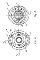
- Figure 2 is an end view of the body coupling component, taken on line 2-2 of Figure 1;
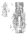
- Figure 3 is a longitudinal sectional view, taken on line 3-3 of Figure 2, showing the internal construction and elements of the body component of the coupling assembly;
- Figure 3A is an enlarged view of the end portion of the body valve element D (the seal elements are shown in a non-sealed condition);
- Figure 4 is a cross-sectional view taken on line 4-4 of Figure 3;
- Figure 5 is a longitudinal sectional view of the stem coupling component (the view is taken on line 5-5) of Figure 1;
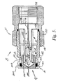
- Figure 6 is a longitudinal sectional view of the coupling assembly showing the stem and body components in a connected position;
- Figure 7 is a greatly enlarged view of the circled area of Figure 6;
- Figure 7A is a cross sectional view taken on line 7A-7A of Figure 7;
- Figure 8 is a cross-sectional view taken on line 8-8 of Figure 6; and
- Figures 9 to 13 are perspective views of various coupling components
- Figure 1 shows a mating pair of body and stem coupling members or assemblies A and B respectively. In Figure 1, the coupling components are in a disconnected relationship but in alignment as they are about to be connected upon movement axially towards one another.
- As illustrated in Figure 3, the body assembly A includes a main body assembly C which has a substantially annular configuration and carries a body valve element D axially therein. A slide valve assembly E is carried within the annular chamber and mounted for axial sliding movement between an axially outer position (as shown in Figure 3) wherein it is sealingly engaged with the valve element D to a leftward position wherein flow can take place through the assembly. The slide sleeve assembly E is normally continually biased to the right as illustrated in Figure 3 by a compression
type coil spring 12. - Referring to Figure 5, it will be seen that the stem assembly B includes an elongated hollow stem body assembly F which houses a poppet valve element G that is carried and guided by a guide assembly H. An elongated compression
type coil spring 14 functions to maintain the poppet element G continually biased to the left hand closed position illustrated in Figure 5. In this position, the poppet element G cooperates with theseal assembly 16 to close the passage through the stem body assembly F. - When a pair of mated body and stem assemblies are to be joined they are positioned in the aligned relationship illustrated in Figure 1. As they are brought axially together to move them to the coupled position illustrated in Figure 6, it will be seen that the small diameter stem end of the stem body assembly F comes into engagement with the outer end of slide assembly E of body assembly A. As the two components are moved toward one another, the slide sleeve assembly E is moved to a left hand position as illustrated in Figure 6. Simultaneously with this final assembly movement, the poppet valve element G is driven to the right against the bias of
spring 14. As the assemblies are moved to the Figure 6 position, sleeve hook assemblies J and the locking dog detent assemblies K move to their locked positioned to maintain the components in the coupled condition of Figure 6. When the assemblies are in their coupled or connected position, the parts are arranged generally as shown in Figure 6 and fluid flow can take place through the connected assemblies. - Referring again more particularly to Figures 2 through 4, the overall arrangement of the body component A and its preferred form of construction will be described. As illustrated therein, the body C of body assembly A generally comprises a
first body component 16 which has a reduced diameter righthand end portion 18 and a central stepped diameter passage 20 formed therethrough. The left hand end of passage 20 is provided with suitable threads or other connecting means to allow the body assembly A to be connected to associated fluid lines. Joined tobody component 16 is an outer sleeve likebody component 22. In the embodiment under consideration, thebody component 22 is releasably joined tobody component 16 by suitable threads 24. It should also be noted that a relatively short cylindrical abutment sleeve orhousing member 26 having a radially inwardly extendingflange 28 is located radially outwardly of the left hand end (as viewed in Figure 2) of thebody component 22. As can be seen, it is held and clamped in position by having its inwardly extendingend flange 28 captured between the threadedlyconnected body components - Fixedly mounted within the reduced diameter end portion of
body component 16 is the body valve assembly D. Body valve assembly D includes an elongated rigid body orbolt portion 30 which terminates in a generallycylindrical valve section 32. As best shown in Figure 4, thebody section 30 is generally flat and of a width "W" to be closely received in the reduced diameter portion of passage 20. This results in a pair of flow passages 33 on opposite sides of thebolt portion 30. In the embodiment under consideration, the body valve D is mechanically joined tobody component 16 by three axially displacedequal crimps 34. In particular, the exterior of thebolt portion 30 of the body valve D is provided with three equally spaced grooves slots 36 on each lateral edge thereof. The material of the reduced diameter section ofbody 16 is thereafter mechanically crimped into the grooves 36 firmly locking the body valve D in position. In conjunction with this assembly, it should be noted that thebody 30 includes radially outwardly extending shoulder or flange portions 38 which are located at a diameter greater than the internal diameter of the reduced diameter section of passageway 20. Additionally, this assists in locating thebolt portion 30 for the crimping operation, the radial dimension of the sections 38 is greater than the minimum internal diameter of the slide sleeve assembly E. As will subsequently be apparent, this acts to prevent the body valve from being expelled from the assembly if failure occurs. - As best shown in Figures 2 and 4,
body component 22 preferably has a generally elliptical or oval exterior shape in planes perpendicular to the longitudinal axis. It is positioned with the major axis of the ellipse to extend coextensive with centerline C₁. The minor axis is, of course, located on centerline axis C₂. The center ofelement 22 has acylindrical bore 40 which cooperates with the reduced diameter section ofcomponent 16 to define an outwardly openannular chamber 42. - Mounted within
annular chamber 42 for axial sliding movement on the reduced diameter section ofbody section 16 is the previously mentioned slide sleeve assembly E. The assembly E comprises a generally cylindricalslide sleeve member 44 which has a stepped internal passageway including a first section 46 which is sized to be closely received on the exterior of the reduced diameter section ofbody section 16. A reduceddiameter section 48 is sized so as to closely and sealingly receive thecylindrical end section 32 of the body valve D in the manner illustrated in Figure 3. It should be noted that the exterior ofsleeve 44 has a radially outward extending flange 50 which is sized to be received closely within the major internal diameter ofbody section 22.Slide sleeve member 44 is continually biased to the right hand position illustrated in Figure 3 by the previously mentionedcompression spring 12. Movement to the right is limited by engagement of the flange 50 with the internal shoulder 52 formed inbody section 22. The arrangement of the flange 50 and internal shoulder 52 which limits movement of thesleeve member 44 produces both structural and functional advantages. More particularly, because thebody bolt 30 is not required to restrain thesleeve member 44, the bolt can be small and of lesser cross-section thus allowing greater flow area and reduced flow resistance. In addition, with the subject design axial pressure thrust is contained and resisted by thebody section 22 in both the coupled and uncoupled conditions. Because of this, no additional material or strength considerations are required. - A suitable O-ring seal 54 and a backup ring 56 are carried within an external circumferential groove formed on the right hand end of the reduced diameter section of
body component 16. This provides a fluid tight seal between the sliding surfaces of thesleeve member 44 and the reduced diameter section ofbody member 16. - Sealing between the right hand and/or
cylindrical portion 32 of the body valve D and the interior reduceddiameter section 48 of theslide element 44 is accomplished by an improved seal assembly best illustrated in Figure 3A. As shown in Figure 3A, thecylindrical section 32 of the body valve D is provided with a circumferentially extending contouredgroove 58 including a relatively shallow axially outward groove section 60 and a significantlydeeper groove section 62. This arrangement allows use of a continuous PTFE ring 64 to function as a backup ring for the associated O-ring seal element 66. As can be seen from Figure 3A, the arrangement of the contouredgroove 58 is such that the effective outer diameters of the backup ring and O-ring are the same but they can have significantly different internal diameters. This allows the use of a continuous backup ring of relatively low elasticity teflon since the backup ring is not required to be greatly elongated during its installation in the backup ring portion of thegroove 58. Thus, a solid backup ring can be employed in a one piece O-ring groove in conjunction with an O-ring having a large wire diameter to toroidal diameter ratio. This, of course, provides distinct operating advantages without increasing manufacturing problems. - With particular importance to the subject invention is the construction of the slide hook assembly J and its operational relationship to the wiper can assembly I. Referring in particular to Figures 3, 7 and 9, the overall arrangement of the wiper can assembly I can be understood. As shown therein, the wiper can assembly I includes a generally cylindrical thin metal can like
element 70 having a cylindrical configuration and a radially inwardly extending forward flange or endwall 72. The main body portion of thecan member 70 has an opened internal diameter sized so as to allow it to be closely and slidably received on the outer surface of the intermediate portion ofsleeve member 44. The inner diameter of theflange end section 72 is, however, only slightly larger than the outer diameter of the reduced diameter outer end portion of thesleeve 44. The relationship of theend face 72 to thebody member 22 and thesleeve 44 is best illustrated in Figure 2. Note that the end wall orflange 72 acts to substantially completely fill or, in effect, close the outer end of the body member A when the coupling is in a disconnected condition as shown in Figures 2 and 3. This prevents dirt and foreign materials from entering into the internal mechanism of the coupling. To further enhance this function of the wiper can element 70 a circumferentially continuous resilient wiper member 74 is carried by theflange section 72 and is sized so that its inner diameter is slightly smaller than the outer diameter of the end section ofmember 44. This produces a movable seal and wiping element as thecan element 70 is axially moved relative to thesleeve member 44. The resilient wiper member 74 is firmly maintained in position adjacent theflange 72 by ametal backup ring 76 which is maintained in engagement against the rear side of the wiper ring 74 by acompression spring 78. As best seen in Figure 3, thecompression spring 78 has a generally conical shape and acts between a shoulder onsleeve member 44 and thebackup ring 76. Additionally, thecompression spring 78 acts to maintain the wiper canelement 70 continually biased toward the open outer end of the body assembly A. - The limit of outer movement of the wiper can assembly I is defined by the slide hook assembly J. As illustrated in Figures 2, 3, 7 and 10, the subject device uses two
slide hook members 80 located on diametrically opposite sides of thesleeve member 44. Thehook members 80 have the overall configuration best seen in Figure 10 and include an inwardly extendinghook portion 82 which is received in acircumferential groove 84 formed insleeve 44 at the general location illustrated. Thehook members 80 are maintained in engagement with thegroove 84 by their relationship with the cylindrical wiper can 70. As illustrated in Figures 7, 7A, and 9 the wiper canelement 70 includeselongated slots 86 through which thehook members 82 extend. Additionally, eachhook member 80 is provided with inwardly extendingside grooves 88 that receive the sides of theslot 86. As illustrated in Figure 9, entry of thehook 82 during assembly can take place through a slightly widenedpart 87 in theslot 86. The relationship thus far described allow the wiper can element to move axially relative to the slide hook while permitting thehook 80 to maintain positive engagement with thegroove 84 in theslide 44. Additionally, as best illustrated in Figures 2 and 4, the slide hooks 80 and the wiper can 70 are axially guided byelongated slots 90 formed radially outward from the interior surface ofbore 40 ofbody member 22. As illustrated, the grooves are located in diametrically opposite sides and are sized so as to closely receive the sides of the respective slide hooks 80. This maintains the slide hooks oriented in the position shown and prevents rotation of the wiper can assembly I. - The relationship of the
slide hook elements 80 to the stem coupling component B will subsequently be described in conjunction with the description of the stem coupling component. For the present, however, and continuing with the description of the body component assembly A, the assembly further includes the locking dog detent assembly K which functions to maintain the body assembly A and the stem assembly in the connected relationship shown in Figure 6 until it is desired to release the locking dogs. As best illustrated in Figures 2, 3 and 8 there are two lockingdog elements 94 positioned on diametrically opposite sides of body assembly A and mounted for radial movement toward and away from the axial centerline along centerline C₂. The lockingdogs 94 have the general configuration best shown in Figure 11. In particular, the lockingdogs 94 have opposed generallyparallel side walls 96 and 98 (see Figure 3) which are sized so as to be closely and slidably received in a transversely extendingslot 100 formed throughbody component 22. Theslots 100 guide the radial movement of thedog 94 and constrain them against undesired axial movement. The locking dogs are constrained against circumferential movement by having a lowerrectangular end section 102 which extends through a rectangular opening connecting betweenslot 100 and the annular chamber withinmember 22. This rectangular opening is provided by a longitudinally extending slot 104 formed from theinner wall 40 ofmember 22. - The radial movement of the locking dogs 98 is controlled by an
external control sleeve 110 which is mounted for axial sliding movement between an outermost coupled position illustrated in Figure 6 and an innermost uncoupled position illustrated in Figure 3. In the embodiment under consideration, thecontrol sleeve 110, as well as the previously discussedbody component 22, is formed from powdered metal and has the exterior configuration best seen in Figures 1 through 4. As illustrated therein,sleeve 110 has an internal open configuration to closely receive the exterior ofbody component 22. The exterior configuration ofcontrol sleeve 110 preferably has an oval or generally elliptical shape with the major axis of the ellipse extending in the direction of centerline C₂. As is apparent from Figures 2 and 4, the oval or elliptical exterior surfaces of thebody component 22 and the oval inner opening ofcontrol sleeve 110 maintains the desired circumferential orientation between these components and, further, allows the body end sleeve to have maximum strength in those areas and directions where such strength is required. - As illustrated in Figures 2 and 3, the
operating sleeve 110 includes alongitudinally extending groove 112 that is positioned to engage the lateral ends of thedogs 94. In addition, the groove is contoured as best shown in Figure 3. Note that thegroove 112 has a maximum radial depth at the outer end to permit theindividual dogs 94 to assume their radial outermost position and permit thesleeve element 44 to assume the right hand closed position. However, when the components are in the coupled position shown in Figure 6, thesleeve 44 and the wiper canelement 70 are in their maximum left hand position and the dog elements 9 have then moved radially inward into engaged position with thestem portion 152 of stem assembly B as illustrated. - In order to allow the
control sleeve 110 to properly perform its function, it is maintained under a continual bias to the right toward the position shown in Figure 6. Movement to the right is limited by engagement of the axially inner end ofgroove 112 with the radial outer edge of the associateddog elements 94. Biasing of theoperating sleeve 110 is accomplished by a compression spring 116 which acts between theend wall 28 ofsleeve 26 and the end of thesleeve 110. - In order to permit the coupled assembly to be uncoupled from the position shown in Figure 6, it is necessary to slide the
operating sleeve 110 to the left to bring the radially outer sections 113 ofgrooves 112 into alignment with their respective locking dog. This position is shown in Figure 3. In order to move theoperating sleeve 110 to the position shown in Figure 3, it must be moved against the bias of the spring 116. In addition, the subject device includes alock button assembly 120 which prevents inadvertent release movement of theslide 110 by requiring a separate radial inward movement of thelock button assembly 120 before it is possible to slide theoperating sleeve 110 against the bias of spring 116. As best illustrated in Figures 3, 6 and 12, thelock button assembly 120 includes a stamped metallock button element 122 which is suitably mounted in an opening 124 formed through theoperating sleeve 110. This allows the outer surface of theelement 122 to be exposed for manual access. Thebutton element 122 is maintained in its operating position by a leaf spring element 126 (see Figures 3 and 12) which has an end portion 128 suitably received in a recess formed in the interior of theoperating sleeve 110. The upper end or left hand portion of theleaf spring 126 is suitably received under thebutton 122 and maintains it biased to the position shown in Figure 6. In the Figure 6 position, the pair ofstop elements 130 extend upwardly from the surface ofelement 122 to a position for engagement with the end 26A ofsleeve 26. As shown in Figure 6, this prevents axial movement of operatingsleeve 110 unless thebutton 122 is pivoted inwardly to a position wherein theelements 130 can pass under thesleeve 26. Figure 3 illustrates thebutton element 122 in this depressed position. With respect to thebutton 122 it should be noted that it is arranged such that considering the positioning of thespring 126 and the shape of thebutton 122 rotation takes of this button during the release operation takes place about the inner corner of opening 124. Since the rotation is about an axis that is further inward than the OD of the operating sleeve release is less likely to be a problem with this particular design. - Referring to Figures 5 and 6, the overall arrangement of the stem assembly B will now be described. Basically, the stem assembly B comprises a main stem body assembly F which is a two part assembly comprises a
main body component 150 and a threadedly connectedstem component 152. Themain body component 150 is generally cylindrical with external wrench flats as shown in Figure 1. Afirst end 154 is suitably provided with internal threads to permit connection of the stem assembly to associated piping, tubing or the like. Thesecond end 156 is threadedly connected to thestem member 152 and sealing between thecomponents seal ring 158 captured between suitable internal shoulders. Thestem member 152 is provided with a stepped diameterinternal passageway 160 which terminates in a reduced diameter outer end which receives the generally cylindrical poppet valve member G. A suitable O-ring 162 and an associatedbackup ring 164 is received in agroove 166 formed about the inner end ofstem 152. The O-ring 162 is sized so as to be closely received about the outer surface of the poppet G to provide a fluid tight seal relative thereto. Outward movement of the poppet is limited by cooperatingshoulder passageway 160 respectively. - As previously mentioned, the poppet element G is maintained continually under a bias toward the position illustrated in Figure 5 by the previously mentioned
spring 14 and the guide assembly H. - The guide assembly H is best shown in Figure 13 and comprises a
first support member 176 which is comprised of two generally T-shapedcomponents 177, 178 which are interfitted as shown to provide a support base and upwardly extending guide stems 180. The support base and the guide stem have a generally X-shaped configuration in planes transverse to their longitudinal axis. Amovable guide member 182 is provided with a central elongated slot 184 to provide a pair oflegs 186 which can extend on diametrically opposite sides of theguide post 180 for guide movement relative thereto. A pointedouter end 188 on themember 182 is arranged to engage within aninternal bore 190 formed in the poppet element G. As can be appreciated, this assembly guides the poppet during reciprocatory movement from the position shown in Figure 5 to the open position shown in Figure 6. The exterior surface of thestem portion 152 is provided with a pair of axially circumferentially extendinggrooves outer groove 200 is arranged to provide a point of engagement for the slide hooks 80. As illustrated in Figure 7 thehook 80 has an inwardly extendinghook end portion 204 which is adapted to be received within thegroove 200 when the components are in the coupled position of Figures 6 and 7. Similarly, thegroove 202 is arranged to receive the lockingdogs 94 and maintain the components in the coupled position shown in Figure 6. It should be appreciated that the contour of thegroove 202 is such as to provide a camming action against the suitable inclined inner end of the locking dogs 94. Thus, when theoperating sleeve 110 is moved to its leftmost position the stem assembly B can be withdrawn from the body assembly A. During this withdrawal motion, the locking dogs 98 are cammed outwardly and thesleeve member 44 is pulled to the closed position of Figure 3 because of the engagement between the sleeve hooks and thegroove 200 instem member 152. When the sleeve hooks reach the position shown in Figure 3 a radial relief section 210 ingroove 90 allows the sleeve hooks to move radially outward releasing thestem element 152. - As is apparent, the design of the slide hooks and their relationship to the stem coupling assembly B is such that the design can readily be used to provide a keyed arrangement between various different coupling members. Note that by shaping or modifying the configuration of the stem engaging portion of the
hook 80, and by changing its axial length relative to the stem, it is possible to limit the stem assemblies which can be connected with any particular body assembly. This provides an extremely simple and rapid way of assuring that only matched pairs of body and stem coupling assemblies can be joined. Thus, matched, coded coupling sets can be provided merely by changing thestem member 152 on the stem coupling assembly and the pairs ofhooks 80. Note that if there is not a proper match between the hook portion of theslide hook 80 and thegroove 202 of the mating stem, it is not possible for the components to be assembled. This is apparent from FIGURE 3. That is, if thehook member 80 cannot move radially inward into engagement in acorresponding groove 202 on the stem coupling assembly B, it cannot pivot inwardly to fit within the radially reduced section ofgroove 90. This, of course, prevents axial engagement and connection of the components. - The invention has been described with reference to a preferred embodiment, obviously modifications and alterations of this preferred embodiment will occur to others upon a reading and understanding of the specification. It is, of course, intended to include all such alterations and modifications as part of the invention insofar as they come within the scope of the claims hereto.
Claims (34)
Applications Claiming Priority (2)
| Application Number | Priority Date | Filing Date | Title |
|---|---|---|---|
| US07/369,070 US4982761A (en) | 1989-06-20 | 1989-06-20 | Valved quick connect/disconnect coupling |
| US369070 | 1989-06-20 |
Publications (3)
| Publication Number | Publication Date |
|---|---|
| EP0404495A2 true EP0404495A2 (en) | 1990-12-27 |
| EP0404495A3 EP0404495A3 (en) | 1991-04-24 |
| EP0404495B1 EP0404495B1 (en) | 1993-09-22 |
Family
ID=23453982
Family Applications (1)
| Application Number | Title | Priority Date | Filing Date |
|---|---|---|---|
| EP19900306642 Expired - Lifetime EP0404495B1 (en) | 1989-06-20 | 1990-06-19 | Quick-connect/disconnect coupling |
Country Status (6)
| Country | Link |
|---|---|
| US (1) | US4982761A (en) |
| EP (1) | EP0404495B1 (en) |
| JP (1) | JPH0396790A (en) |
| CA (1) | CA2019227A1 (en) |
| DE (1) | DE69003467T2 (en) |
| HK (1) | HK122696A (en) |
Cited By (1)
| Publication number | Priority date | Publication date | Assignee | Title |
|---|---|---|---|---|
| WO2019207321A1 (en) * | 2018-04-27 | 2019-10-31 | John Guest International Limited | A collet for locking a tube in a coupling body |
Families Citing this family (28)
| Publication number | Priority date | Publication date | Assignee | Title |
|---|---|---|---|---|
| US5123447A (en) * | 1991-03-11 | 1992-06-23 | Calvin John H | Quick disconnect coupling |
| US5123446A (en) * | 1991-07-05 | 1992-06-23 | Aeroquip Corporation | Dual seal coupling |
| SE470452B (en) * | 1992-10-16 | 1994-04-11 | Bjoern Engdahl | Hose connection for compressed air with means for pressure relief at disassembly |
| JPH06288405A (en) * | 1993-03-31 | 1994-10-11 | Japan Aircraft Mfg Co Ltd | Connection mechanism |
| JPH11500517A (en) * | 1995-01-06 | 1999-01-12 | コールダー・プロダクツ・カンパニー | Low outflow high flow quick connect valve assembly |
| US6082401A (en) * | 1995-01-06 | 2000-07-04 | Colder Products Company | Low spill high flow quick coupling valve assembly |
| TW327672B (en) * | 1995-10-05 | 1998-03-01 | Babcock & Wilcox Co | Field serviceable fill tube for use on heat pipes |
| SE506405C2 (en) * | 1996-03-22 | 1997-12-15 | Nyberg Bo Erik | Quick release with pressure relief for safe release |
| US6161578A (en) * | 1996-10-09 | 2000-12-19 | Colder Products Company | Low spill high flow quick coupling valve assembly |
| FR2786849B1 (en) * | 1998-12-03 | 2001-01-26 | Staubli Sa Ets | QUICK SAFETY CONNECTOR FOR REMOVABLE JOINING OF PIPES |
| US6460899B1 (en) * | 1999-02-11 | 2002-10-08 | Airmo, Inc. | Disconnect coupling |
| JP2002102105A (en) * | 2000-10-02 | 2002-04-09 | 津杰 ▲リュウ▼ | Holder without stem |
| FR2822920B1 (en) * | 2001-04-03 | 2003-10-31 | Staubli Sa Ets | QUICK CONNECTOR FOR THE REMOVABLE JOINT OF TWO PIPES AND THE USE THEREOF |
| ITMI20011105A1 (en) * | 2001-05-25 | 2002-11-25 | Faster Srl | QUICK COUPLING WITH A FLAT FACE, WITH MEANS TO AVOID A LOSS OF HYDRAULIC FLUID DURING THE COUPLING OR DISCONNECTION PHASE |
| US7712794B2 (en) * | 2003-05-02 | 2010-05-11 | Asia Pacific Fuel Cell Technologies, Ltd. | Rapid coupling device for hydrogen storage canister |
| SE529075C2 (en) * | 2005-05-23 | 2007-04-24 | Bjoern Engdahl | Combined locking and locking body |
| TW200717906A (en) * | 2005-07-18 | 2007-05-01 | Bic Soc | Fuel supply with improved connecting valve |
| FR2895058B1 (en) * | 2005-12-20 | 2008-03-14 | Parker Hannifin France Sas Soc | RIGID COUPLER FOR PRESSURIZED FLUID PIPES, FOR CONNECTING THESE PIPES WHILE PRESSURIZED FLUID SUBSISTS IN ONE OF THESE PIPES |
| EP2024673B1 (en) * | 2006-05-15 | 2013-05-15 | Colder Products Company | Aseptic coupling devices |
| AU2008323018A1 (en) * | 2007-11-12 | 2009-05-22 | Australasian Food Group Pty Ltd. | Fitment for connecting a container to a dispensing appliance |
| US8191575B2 (en) * | 2008-04-11 | 2012-06-05 | International Business Machines Corporation | Double poppet quick connect |
| US20100276624A1 (en) * | 2009-05-01 | 2010-11-04 | Swagelok Company | Seal with seal support shoulder |
| US8776828B2 (en) * | 2009-07-20 | 2014-07-15 | Illinois Tool Works Inc. | Fluid dispensing assembly |
| EP2511584B1 (en) * | 2011-04-14 | 2014-01-08 | Cejn AB | Compressed air coupling |
| US10941892B2 (en) | 2017-02-17 | 2021-03-09 | Hewlett Packard Enterprise Development Lp | Valved connector |
| US10814533B2 (en) | 2017-11-30 | 2020-10-27 | The Boeing Company | Systems and methods for applying vacuum pressure to composite parts |
| US11608919B2 (en) * | 2018-02-27 | 2023-03-21 | Intel Corporation | Universal quick disconnect |
| JP2023549893A (en) * | 2020-11-16 | 2023-11-29 | コルダー プロダクツ カンパニー | fluid handling fittings |
Citations (7)
| Publication number | Priority date | Publication date | Assignee | Title |
|---|---|---|---|---|
| US3613726A (en) * | 1965-12-02 | 1971-10-19 | Purolator Products Inc | Balanced pressure coupling |
| US4086939A (en) * | 1976-09-03 | 1978-05-02 | Snap-Tite, Inc. | Coupling assembly |
| GB2068069A (en) * | 1980-01-30 | 1981-08-05 | Ekman K R | Disconnectible pipe couplings |
| GB2166501A (en) * | 1984-11-01 | 1986-05-08 | Sterling Hydraulics Limited | Sealing member |
| US4596272A (en) * | 1984-02-27 | 1986-06-24 | Swagelok Company | Coupling |
| US4637432A (en) * | 1983-01-19 | 1987-01-20 | Swagelok Company | Coupling |
| EP0233766A2 (en) * | 1986-02-14 | 1987-08-26 | Swagelok Quick-Connect Co. | Seal assembly |
Family Cites Families (19)
| Publication number | Priority date | Publication date | Assignee | Title |
|---|---|---|---|---|
| US3123099A (en) * | 1964-03-03 | High pressure fluid coupling | ||
| US2208286A (en) * | 1937-01-26 | 1940-07-16 | Berger Julius | Pipe coupling |
| US2425500A (en) * | 1943-07-07 | 1947-08-12 | Wiggins Irene Lane | Valved coupling |
| US2381962A (en) * | 1943-12-09 | 1945-08-14 | Wheaton Brass Works | Hose coupling |
| US2413978A (en) * | 1945-05-08 | 1947-01-07 | Wheaton Brass Works | Quick hose coupling |
| US2727759A (en) * | 1951-10-27 | 1955-12-20 | Hughes Tool Co | Valved couplers for fluid-conducting conduits |
| BE542454A (en) * | 1954-11-08 | 1900-01-01 | ||
| US2951713A (en) * | 1956-03-12 | 1960-09-06 | Hoffstrom Bo Nilsson | Couplings |
| US2888278A (en) * | 1956-06-18 | 1959-05-26 | E B Wiggins Oil Tool Company I | Coupling with automatically actuated cam sleeve |
| US2952482A (en) * | 1957-02-04 | 1960-09-13 | E B Wiggins Oil Tool Company I | Coupling with automatically actuated cam sleeve |
| US3039794A (en) * | 1958-07-14 | 1962-06-19 | On Mark Couplings Inc | Quick disconnect coupling for high pressure fluids |
| US3028179A (en) * | 1958-12-29 | 1962-04-03 | Weatherhead Co | Self-sealing locking coupling with manipulator and pivoted latch means |
| US3113588A (en) * | 1960-05-09 | 1963-12-10 | On Mark Couplings Inc | Fluid conduit coupling |
| US3097867A (en) * | 1961-04-13 | 1963-07-16 | Snap Tite Inc | Coupling |
| US3234965A (en) * | 1962-09-17 | 1966-02-15 | E B Wiggins Oil Tool Company I | Coupling assembly |
| US3367366A (en) * | 1965-10-11 | 1968-02-06 | Universal Oil Prod Co | Disconnect with minimum inclusion |
| US3435848A (en) * | 1967-03-20 | 1969-04-01 | James R Johnston | Fluid line coupler |
| DE2138103C3 (en) * | 1971-07-30 | 1980-04-30 | Otto Dipl.-Ing. 5828 Ennepetal Busselmeier | Quick coupling for liquid and gas lines |
| US4693497A (en) * | 1986-06-19 | 1987-09-15 | Cameron Iron Works, Inc. | Collet connector |
-
1989
- 1989-06-20 US US07/369,070 patent/US4982761A/en not_active Expired - Fee Related
-
1990
- 1990-06-18 CA CA 2019227 patent/CA2019227A1/en not_active Abandoned
- 1990-06-19 DE DE1990603467 patent/DE69003467T2/en not_active Expired - Fee Related
- 1990-06-19 EP EP19900306642 patent/EP0404495B1/en not_active Expired - Lifetime
- 1990-06-20 JP JP2162528A patent/JPH0396790A/en active Pending
-
1996
- 1996-07-11 HK HK122696A patent/HK122696A/en not_active IP Right Cessation
Patent Citations (7)
| Publication number | Priority date | Publication date | Assignee | Title |
|---|---|---|---|---|
| US3613726A (en) * | 1965-12-02 | 1971-10-19 | Purolator Products Inc | Balanced pressure coupling |
| US4086939A (en) * | 1976-09-03 | 1978-05-02 | Snap-Tite, Inc. | Coupling assembly |
| GB2068069A (en) * | 1980-01-30 | 1981-08-05 | Ekman K R | Disconnectible pipe couplings |
| US4637432A (en) * | 1983-01-19 | 1987-01-20 | Swagelok Company | Coupling |
| US4596272A (en) * | 1984-02-27 | 1986-06-24 | Swagelok Company | Coupling |
| GB2166501A (en) * | 1984-11-01 | 1986-05-08 | Sterling Hydraulics Limited | Sealing member |
| EP0233766A2 (en) * | 1986-02-14 | 1987-08-26 | Swagelok Quick-Connect Co. | Seal assembly |
Cited By (1)
| Publication number | Priority date | Publication date | Assignee | Title |
|---|---|---|---|---|
| WO2019207321A1 (en) * | 2018-04-27 | 2019-10-31 | John Guest International Limited | A collet for locking a tube in a coupling body |
Also Published As
| Publication number | Publication date |
|---|---|
| JPH0396790A (en) | 1991-04-22 |
| EP0404495B1 (en) | 1993-09-22 |
| HK122696A (en) | 1996-07-19 |
| EP0404495A3 (en) | 1991-04-24 |
| DE69003467D1 (en) | 1993-10-28 |
| US4982761A (en) | 1991-01-08 |
| CA2019227A1 (en) | 1990-12-20 |
| DE69003467T2 (en) | 1994-01-20 |
Similar Documents
| Publication | Publication Date | Title |
|---|---|---|
| EP0404495B1 (en) | Quick-connect/disconnect coupling | |
| US4485845A (en) | Quick disconnect coupling | |
| CA1281258C (en) | Poppet valve | |
| EP0753120B1 (en) | Deep drawn quick connect coupling | |
| CA1173074A (en) | Quick connect coupling | |
| US4863201A (en) | Coupling assembly | |
| CA2575483C (en) | Stub out fluid quick connector with shut off valve interface | |
| US5988705A (en) | Quick connect coupling | |
| US4150691A (en) | Quick disconnect coupling | |
| EP1635106A2 (en) | Fluid quick connect with adjustable flow control valve | |
| US4637432A (en) | Coupling | |
| US6637779B2 (en) | Fluid quick connector with grooved endform | |
| US4685490A (en) | Coupling | |
| US3174508A (en) | Double-end shut-off quick-connect tube coupling | |
| CA2641111C (en) | Universal safety coupler | |
| US4799512A (en) | Coupling assembly | |
| US4986304A (en) | Quick and dry coupling | |
| GB2311347A (en) | Subsea coupling with frustoconical metallic seal | |
| US6802491B1 (en) | Fluid shut off valve cartridge with quick connection | |
| US5092363A (en) | Quick and dry coupling | |
| EP1479962A1 (en) | Quick coupling device | |
| CA2216649A1 (en) | Quick connector having ring for confirming proper connection |
Legal Events
| Date | Code | Title | Description |
|---|---|---|---|
| PUAI | Public reference made under article 153(3) epc to a published international application that has entered the european phase |
Free format text: ORIGINAL CODE: 0009012 |
|
| AK | Designated contracting states |
Kind code of ref document: A2 Designated state(s): BE DE FR GB IT NL |
|
| PUAL | Search report despatched |
Free format text: ORIGINAL CODE: 0009013 |
|
| RHK1 | Main classification (correction) |
Ipc: F16L 37/28 |
|
| AK | Designated contracting states |
Kind code of ref document: A3 Designated state(s): BE DE FR GB IT NL |
|
| 17P | Request for examination filed |
Effective date: 19910926 |
|
| 17Q | First examination report despatched |
Effective date: 19920724 |
|
| GRAA | (expected) grant |
Free format text: ORIGINAL CODE: 0009210 |
|
| AK | Designated contracting states |
Kind code of ref document: B1 Designated state(s): BE DE FR GB IT NL |
|
| REF | Corresponds to: |
Ref document number: 69003467 Country of ref document: DE Date of ref document: 19931028 |
|
| ITF | It: translation for a ep patent filed |
Owner name: ING. C. GREGORJ S.P.A. |
|
| ET | Fr: translation filed | ||
| PLBE | No opposition filed within time limit |
Free format text: ORIGINAL CODE: 0009261 |
|
| STAA | Information on the status of an ep patent application or granted ep patent |
Free format text: STATUS: NO OPPOSITION FILED WITHIN TIME LIMIT |
|
| 26N | No opposition filed | ||
| PGFP | Annual fee paid to national office [announced via postgrant information from national office to epo] |
Ref country code: NL Payment date: 19960328 Year of fee payment: 7 |
|
| PGFP | Annual fee paid to national office [announced via postgrant information from national office to epo] |
Ref country code: GB Payment date: 19960509 Year of fee payment: 7 |
|
| PGFP | Annual fee paid to national office [announced via postgrant information from national office to epo] |
Ref country code: FR Payment date: 19960607 Year of fee payment: 7 |
|
| PGFP | Annual fee paid to national office [announced via postgrant information from national office to epo] |
Ref country code: DE Payment date: 19960625 Year of fee payment: 7 |
|
| PGFP | Annual fee paid to national office [announced via postgrant information from national office to epo] |
Ref country code: BE Payment date: 19960703 Year of fee payment: 7 |
|
| PG25 | Lapsed in a contracting state [announced via postgrant information from national office to epo] |
Ref country code: GB Free format text: LAPSE BECAUSE OF NON-PAYMENT OF DUE FEES Effective date: 19970619 |
|
| PG25 | Lapsed in a contracting state [announced via postgrant information from national office to epo] |
Ref country code: BE Effective date: 19970630 |
|
| BERE | Be: lapsed |
Owner name: SWAGELOK QUICK-CONNECT CO. Effective date: 19970630 |
|
| PG25 | Lapsed in a contracting state [announced via postgrant information from national office to epo] |
Ref country code: NL Effective date: 19980101 |
|
| GBPC | Gb: european patent ceased through non-payment of renewal fee |
Effective date: 19970619 |
|
| PG25 | Lapsed in a contracting state [announced via postgrant information from national office to epo] |
Ref country code: FR Free format text: LAPSE BECAUSE OF NON-PAYMENT OF DUE FEES Effective date: 19980227 |
|
| NLV4 | Nl: lapsed or anulled due to non-payment of the annual fee |
Effective date: 19980101 |
|
| PG25 | Lapsed in a contracting state [announced via postgrant information from national office to epo] |
Ref country code: DE Free format text: LAPSE BECAUSE OF NON-PAYMENT OF DUE FEES Effective date: 19980303 |
|
| REG | Reference to a national code |
Ref country code: FR Ref legal event code: ST |
|
| REG | Reference to a national code |
Ref country code: FR Ref legal event code: ST |
|
| PG25 | Lapsed in a contracting state [announced via postgrant information from national office to epo] |
Ref country code: IT Free format text: LAPSE BECAUSE OF NON-PAYMENT OF DUE FEES Effective date: 20050619 |