EP0404476B1 - Comparator circuitry - Google Patents
Comparator circuitry Download PDFInfo
- Publication number
- EP0404476B1 EP0404476B1 EP90306607A EP90306607A EP0404476B1 EP 0404476 B1 EP0404476 B1 EP 0404476B1 EP 90306607 A EP90306607 A EP 90306607A EP 90306607 A EP90306607 A EP 90306607A EP 0404476 B1 EP0404476 B1 EP 0404476B1
- Authority
- EP
- European Patent Office
- Prior art keywords
- inverting amplifier
- amplifier
- input
- transistor
- coupled
- Prior art date
- Legal status (The legal status is an assumption and is not a legal conclusion. Google has not performed a legal analysis and makes no representation as to the accuracy of the status listed.)
- Expired - Lifetime
Links
- 239000003990 capacitor Substances 0.000 claims abstract description 22
- 230000008878 coupling Effects 0.000 claims description 13
- 238000010168 coupling process Methods 0.000 claims description 13
- 238000005859 coupling reaction Methods 0.000 claims description 13
- 230000000295 complement effect Effects 0.000 claims description 6
- 230000001143 conditioned effect Effects 0.000 claims description 5
- 230000004044 response Effects 0.000 abstract description 8
- 230000035945 sensitivity Effects 0.000 abstract description 4
- 230000002708 enhancing effect Effects 0.000 abstract description 2
- 230000000694 effects Effects 0.000 abstract 1
- 230000008859 change Effects 0.000 description 5
- 238000005516 engineering process Methods 0.000 description 5
- 239000000758 substrate Substances 0.000 description 4
- 230000002411 adverse Effects 0.000 description 3
- 230000008901 benefit Effects 0.000 description 3
- 238000005513 bias potential Methods 0.000 description 2
- 230000003111 delayed effect Effects 0.000 description 2
- 238000010586 diagram Methods 0.000 description 2
- 238000012856 packing Methods 0.000 description 2
- 230000009467 reduction Effects 0.000 description 2
- 230000001172 regenerating effect Effects 0.000 description 2
- 230000004075 alteration Effects 0.000 description 1
- 230000001174 ascending effect Effects 0.000 description 1
- 230000005540 biological transmission Effects 0.000 description 1
- 238000006243 chemical reaction Methods 0.000 description 1
- 238000010276 construction Methods 0.000 description 1
- 230000008030 elimination Effects 0.000 description 1
- 238000003379 elimination reaction Methods 0.000 description 1
- 230000005669 field effect Effects 0.000 description 1
- 238000004519 manufacturing process Methods 0.000 description 1
- 238000005070 sampling Methods 0.000 description 1
- 229920006395 saturated elastomer Polymers 0.000 description 1
- 239000004065 semiconductor Substances 0.000 description 1
Images
Classifications
-
- H—ELECTRICITY
- H03—ELECTRONIC CIRCUITRY
- H03M—CODING; DECODING; CODE CONVERSION IN GENERAL
- H03M1/00—Analogue/digital conversion; Digital/analogue conversion
- H03M1/12—Analogue/digital converters
- H03M1/34—Analogue value compared with reference values
-
- H—ELECTRICITY
- H03—ELECTRONIC CIRCUITRY
- H03K—PULSE TECHNIQUE
- H03K5/00—Manipulating of pulses not covered by one of the other main groups of this subclass
- H03K5/22—Circuits having more than one input and one output for comparing pulses or pulse trains with each other according to input signal characteristics, e.g. slope, integral
- H03K5/24—Circuits having more than one input and one output for comparing pulses or pulse trains with each other according to input signal characteristics, e.g. slope, integral the characteristic being amplitude
- H03K5/2472—Circuits having more than one input and one output for comparing pulses or pulse trains with each other according to input signal characteristics, e.g. slope, integral the characteristic being amplitude using field effect transistors
- H03K5/249—Circuits having more than one input and one output for comparing pulses or pulse trains with each other according to input signal characteristics, e.g. slope, integral the characteristic being amplitude using field effect transistors using clock signals
-
- H—ELECTRICITY
- H03—ELECTRONIC CIRCUITRY
- H03F—AMPLIFIERS
- H03F1/00—Details of amplifiers with only discharge tubes, only semiconductor devices or only unspecified devices as amplifying elements
- H03F1/30—Modifications of amplifiers to reduce influence of variations of temperature or supply voltage or other physical parameters
- H03F1/303—Modifications of amplifiers to reduce influence of variations of temperature or supply voltage or other physical parameters using a switching device
-
- H—ELECTRICITY
- H04—ELECTRIC COMMUNICATION TECHNIQUE
- H04N—PICTORIAL COMMUNICATION, e.g. TELEVISION
- H04N25/00—Circuitry of solid-state image sensors [SSIS]; Control thereof
- H04N25/70—SSIS architectures; Circuits associated therewith
- H04N25/76—Addressed sensors, e.g. MOS or CMOS sensors
- H04N25/78—Readout circuits for addressed sensors, e.g. output amplifiers or A/D converters
Definitions
- This invention relates to comparator circuitry as for an analog-to-digital comparator.
- Digital circuit technology has been developed to the point where it is practical to begin implementing digital signal processing in consumer electronic apparatus. For example, manufacturers are beginning to introduce television receivers and video cassette recorders which incorporate digital electronics to add special features such as freeze frame or picture-in-picture to the receivers.
- ADC analog-to-digital converter
- digital television signal processing it is desirable to sample the television signal at a rate of four times the color subcarrier frequency (about 14.32 MHz), and convert the signal to pulse code modulated (PCM) format with 8-bit resolution.
- PCM pulse code modulated
- MOSFET metal-oxide-semiconductor field effect transistor
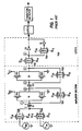
- the comparator circuitry described in U.S. Patent 4,691,189 utilizes two inverting amplifier stages I1, I2 which are capacitively coupled (C2) in cascade, and each of which includes switching circuitry (TG1, TG2) for autozeroing during a portion of each sample period.
- C2 capacitively coupled
- TG1, TG2 switching circuitry
- stray capacitance Associated with the interstage coupling capacitance C2 is a stray capacitance between one of its plates and the circuit substrate, which stray capacitance is of the same order of magnitude as the coupling capacitance itself. This stray capacitance will slow the response time at the output of the first inverting amplifier and thereby slow the response time of the comparator.
- the inverting amplifiers I1, I2 are designed with complementary FET's having a common gate connection and their drain-source conduction paths are serially coupled between supply potentials.
- the autozeroing switches are arranged to connect the output terminals of the inverting amplifiers to their respective input terminals, immediately prior to each signal sampling interval. This form of autozeroing renders the inverting amplifiers sensitive to very slight changes of input potential (a desirable characteristic for this type of comparator).
- the second inverting amplifiers I2 will exhibit a saturated output potential each sample period, requiring a significant potential change during autozero. It will be recognized that the speed at which the inverting amplifiers can autozero is adversely affected by the stray capacitor in the circuit, for example the stray capacitances between C1 and C2 and substrate and the stray capacitances between the autozero switching circuits (TG1, TG2) and substrate.
- a comparator comprising: first and second signal input tenninals for applying a signal potential and a reference potential respectively; a capacitor having first and second terminals; first switch means for alternately coupling said first and second signal input terminals to the first terminal of said capacitor; a first inverting amplifier having an input terminal coupled to the second terminal of said capacitor and having an output terminal; second switch means for alternately coupling and decoupling the input and output terminals of said first inverting amplifier; characterized by: a second inverting amplifier, having an input terminal direct coupled to the output terminal of the first inverting amplifier and having an output terminal, and comprising a first transistor having first and second electrodes with a principal conduction path therebetween, and a control electrode coupled to the output terminal of said first inverting amplifier, and a second transistor having first and second electrodes with a principal conduction path therebetween, and having a control electrode, and wherein the principal conduction paths of said first and second transistors are connected in series, an interconnection of said first and second
- FIGURE 1 is a schematic diagram of a prior art comparator circuit.
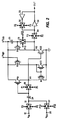
- FIGURE 2 is a schematic diagram of comparator circuitry embodying the present invention.
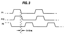
- FIGURE 3 illustrates clocking waveforms useful in describing the operation of the FIGURE 2 circuitry.
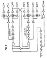
- FIGURE 4 illustrates exemplary circuitry for generating the clock signals illustrated in FIGURE 3.
- switching circuits TG1 and TG2 respectively short circuit the input and output connections of inverting amplifiers I1 and I2. This establishes the input potential of each amplifier midway between its dynamic operating range. These potentials are stored on respective plates of capacitors C1 and C2.
- switching circuit TGR is also short circuited coupling a reference potential to the input plate of capacitor C1. Switching circuits TG1, TG2 and TGR are then simultaneously open circuited. Amplifiers I1 and I2 have significant gain and are now biased at an unstable operating point.
- Switching circuit TGS is then short circuited, coupling the input potential to the plate of capacitor C1. If the input potential is very slightly greater (lesser) than the reference potential the output potential from inverting amplifier I2 will be driven to substantially its positive (negative) output saturation level and thereafter stored in the latch circuitry for a sample period.
- the output potential from inverting amplifier I2 will be driven to substantially its positive (negative) output saturation level and thereafter stored in the latch circuitry for a sample period.
- FIGURE 2 circuitry which operates similarly to the FIGURE 1 circuitry, but is arranged for faster operating performance.
- elements 12, 22, 26, 28, 30 and 32 are switching circuits and may be realized with complementary transistor transmission gates such as the switching circuits TG1 and TG2 in FIGURE 1.
- Input signal to be compared is coupled via a terminal 10 to a switching circuit 12.
- Reference signal against which the input signal is to be compared is coupled via a terminal 20 to a switching circuit 22.
- Switching circuits 12 and 22 are conditioned by substantially anti-phase clock signals P2 and P1D to alternately couple the input and reference signals to a first plate of an input capacitor 24.
- a second plate of the capacitor 24 is coupled to the gate electrode of a p-type transistor P13 biased as a common source amplifier A1.
- An n-type transistor N13 biased as a constant current source, has its drain electrode coupled to the drain electrode of transistor P13 and forms a load impedance for the amplifier.
- the interconnection of transistors N13 and P13 is the output connection of the common source amplifier.
- a switching circuit 26 is coupled between the input and output connections of the common source amplifier.
- Switching circuit 26 is conditioned by a clocking signal P1 to autozero the amplifier stage substantially coincident with switching circuit 22 coupling the reference signal to capacitor 24. See FIGURE 3 for the relative timing of clocking signals P1, P2 and P1D.
- Bias potential for the n-type transistor N13 is provided by a p-type transistor P23 and an n-type transistor N23 having their respective principal conduction paths connected in series between the supply potentials.
- Transistor N23 is coupled as the master transistor of a current mirror amplifier with transistor N13 coupled as the slave transistor.
- the control electrode of transistor P23 is biased at a potential which is about midway between the supply potentials.
- the ratio of transconductances P23/N23 of transistors P23, N23, is equal to the ratio of transconductances P13/N13 of transistors P13 and N13.
- the output connection of the amplifier A1 is connected to the control electrode of a further n-type transistor N33 connected as a common source amplifier A2.
- the load circuit for transistor N33 is provided by a p-type transistor P33 having its drain/source conduction path coupled in series with the drain/source conduction path of transistor N33 between the supply potentials V DD and ground.
- the interconnection of transistors P33 and N33 forms an output connection of the amplifier A2.
- the control electrode of transistor P33 is connected to the output connection of amplifier A2 by the switching circuit 28.
- the switching circuit is controlled by the clock signal P1D. During the intervals that switching circuit 26 couples the input and output connections of amplifier A1 in order to autozero amplifier A1, switching circuit 28 couples the output connection of amplifier A2 to the gate electrode of transistor P33 in order to autozero amplifier A2.
- a capacitor 29 is coupled between the control electrode of transistor P33 and a point of fixed potential, e.g., supply potential V DD or ground potential.
- Capacitor 29 may be designed into the circuit or it may consist of stray capacitance. The capacitor 29 is incorporated to store the autozero bias potential and apply same to the control electrode of transistor P33 when the switching circuit 28 is open circuited.
- Circuit elements 30, 32, 33 and 34 coupled to the output connection of amplifier A2 form a conventional latch circuit to store the results of each comparison for at least one-half of the subsequent sample period.
- Nominally switching circuits 26 and 28 may be controlled by the same clock signals. In a preferred embodiment however, switching circuit 28 will remain closed or short circuited for a short period after switching circuit 26 has been open circuited. The reason is as follows. Consider capacitors 24 and 29 to have the same capacitance value, and transistors P13 and P33 to be complementary to transistors N13 and N33. Under this set of circumstances transistors P13, P33 and N33 will exhibit a like magnitude of gain. Also consider switching circuits 26 and 28 to be similar in construction.
- Switching circuits 26 and 28 due to inherent stray capacitances between their control electrodes and their respective input/output terminals, will couple a portion of the clock signal transients to the control electrodes of transistors P13 and P33 when the switching circuits are open circuited at the termination of the autozero interval.
- the gain of amplifier A1 is "-A”
- the gain of amplifier A2 relative to potentials applied to the control electrode of transistor N33 is "-A”
- the gain of amplifier A2 relative to signals applied to transistor P33 is "-A”.
- switching circuits 26 and 28 simultaneously couple a potential ⁇ V to the control electrodes of transistors P13 and P33 due to clocking transients.
- the potential ⁇ V will create a change in the autozeroed output potentials of amplifiers A1 and A2 equal to -A ⁇ V and ⁇ VA(A-1) ⁇ VA2, respectively.
- One of the implications of this potential change is that at least for output potential swings in the opposite direction, due to a signal comparison, the output at amplifier A2 must go through an added potential excursion of ⁇ VA2 volts, thereby slowing the response time of the circuit.
- a second ramification is a reduction in sensitivity.
- the input to amplifier A2 is direct coupled to the output of amplifier A1 which provides two significant advantages over the capacitive coupling of the prior art circuit of FIGURE 1.
- the control electrode of transistor N33 (and transistors N21 and P21 of FIGURE 1) presents a capacitive load, C, to the output of amplifier A1 (I1). If amplifier A1 were capacitively coupled (by a capacitance C c ) to transistor N13, a division of the output potential V A1 , from amplifier A1 would occur.
- a further advantage of the present invention lies in the positioning of the autozero switching circuit 28. Note in the prior art circuit that during the autozeroing interval the output of amplifier I2 is coupled to the input of amplifier I1 via switching circuits TG1, TG2 and capacitor C2. This connection tends to provide regenerative feedback around the two amplifiers, slowing the autozero response time of the prior art system. In the embodiment of FIGURE 2, regenerative feedback is precluded as no circuit path is provided between the input connection of amplifier A1 and the output connection of amplifier A2.
- the output of amplifier A1 may be coupled to the control electrode of transistor P3 and the switching circuit 28 coupled between the output of amplifier A2 and the control electrode of N33.
- the input to amplifier A1 may be coupled to transistor N13 with transistor P13 operated as a current source load device.
- the FIGURE 2 type comparator circuits coupled to a common input terminal as in a flash ADC. In this instance each of the input connections 20 will be coupled to a different reference voltage incrementally ascending over a range of from ground to supply potential. Assume that the average or D.C. value of the signal applied to the common input terminal is one-half the supply voltage.
- the first inverting amplifier A1 in the FIGURE 2 circuitry may be replaced with an inverting amplifier such as the amplifier I1 illustrated in the FIGURE 1 circuitry.
- the control or gate electrode of transistor N33 is direct coupled to the interconnection of transistors P11 and N11, and transistors P23 and N23 are eliminated.
- FIGURE 3 shows the preferred timing of the clock signals applied to control the switching circuits.
- Desirably clock signals P1 and P2 are antiphase non-overlapping signals.
- FIGURE 4 illustrates exemplary circuitry for generating the clock signals shown in FIGURE 3.
- the delayed signal P1D is produced by generating a delayed version of the signal P1.
- this delay is realized via the inherent delay of series connected gate circuits (e.g., 4 inverter circuits).
Landscapes
- Engineering & Computer Science (AREA)
- Nonlinear Science (AREA)
- Power Engineering (AREA)
- Physics & Mathematics (AREA)
- Theoretical Computer Science (AREA)
- Signal Processing (AREA)
- Multimedia (AREA)
- Amplifiers (AREA)
- Manipulation Of Pulses (AREA)
- Analogue/Digital Conversion (AREA)
- Electronic Switches (AREA)
- Measurement Of Current Or Voltage (AREA)
- Metal-Oxide And Bipolar Metal-Oxide Semiconductor Integrated Circuits (AREA)
- Radar Systems Or Details Thereof (AREA)
- Transmission And Conversion Of Sensor Element Output (AREA)
Abstract
Description
- This invention relates to comparator circuitry as for an analog-to-digital comparator.
- Digital circuit technology has been developed to the point where it is practical to begin implementing digital signal processing in consumer electronic apparatus. For example, manufacturers are beginning to introduce television receivers and video cassette recorders which incorporate digital electronics to add special features such as freeze frame or picture-in-picture to the receivers. In order to accomplish digital processing it is first necessary to convert the received broadcast signal to digital format, and this function is performed by an analog-to-digital converter (ADC). In digital television signal processing it is desirable to sample the television signal at a rate of four times the color subcarrier frequency (about 14.32 MHz), and convert the signal to pulse code modulated (PCM) format with 8-bit resolution. Bipolar ADC's exist which operate satisfactorily at these rates and resolution; however, the technology of choice of performing digital processing in electronic products is metal-oxide-semiconductor (MOS) field effect transistor (FET) technology. The reason is that MOSFET technology permits dense packing of devices with low power dissipation.
- Prior art 8-bit 14 MHz ADC's implemented in MOS technology are currently available; however production yields of such devices are relatively poor. An example of a typical MOS ADC is described in U.S. Patent 4,691,189, which is incorporated herein by reference. Numerous variants of this type of ADC have been designed to increase either its operating speed or its conversion linearity. However, these designs do not provide apparatus with satisfactory performance/yields for video rate signal processing. In the ADC's of the type illustrated in U.S. Patent 4,691,189 performance is traded off against yield, in that the transistor sizes are made extremely small to increase packing density and thereby yield. However, as transistor devices are made smaller, stray capacitances become increasingly more significant, which stray capacitances adversely affect circuit performance. In addition the stray capacitances in MOS circuitry tend to be non-linear with applied potential and therefore are not completely predictable.
- The comparator circuitry described in U.S. Patent 4,691,189, a portion of which is illustrated in FIGURE 1 herein, utilizes two inverting amplifier stages I1, I2 which are capacitively coupled (C2) in cascade, and each of which includes switching circuitry (TG1, TG2) for autozeroing during a portion of each sample period. Associated with the interstage coupling capacitance C2 is a stray capacitance between one of its plates and the circuit substrate, which stray capacitance is of the same order of magnitude as the coupling capacitance itself. This stray capacitance will slow the response time at the output of the first inverting amplifier and thereby slow the response time of the comparator.
- In the comparator design of U.S. Patent 4,691,189 the inverting amplifiers I1, I2 are designed with complementary FET's having a common gate connection and their drain-source conduction paths are serially coupled between supply potentials. The autozeroing switches are arranged to connect the output terminals of the inverting amplifiers to their respective input terminals, immediately prior to each signal sampling interval. This form of autozeroing renders the inverting amplifiers sensitive to very slight changes of input potential (a desirable characteristic for this type of comparator).
- For every comparator in the ADC, and there may be 256 comparators in an 8-bit flash ADC, at least all of the second inverting amplifiers I2 will exhibit a saturated output potential each sample period, requiring a significant potential change during autozero. It will be recognized that the speed at which the inverting amplifiers can autozero is adversely affected by the stray capacitor in the circuit, for example the stray capacitances between C1 and C2 and substrate and the stray capacitances between the autozero switching circuits (TG1, TG2) and substrate.
- According to the invention, there is provided a comparator comprising:
first and second signal input tenninals for applying a signal potential and a reference potential respectively;
a capacitor having first and second terminals;
first switch means for alternately coupling said first and second signal input terminals to the first terminal of said capacitor;
a first inverting amplifier having an input terminal coupled to the second terminal of said capacitor and having an output terminal;
second switch means for alternately coupling and decoupling the input and output terminals of said first inverting amplifier; characterized by:
a second inverting amplifier, having an input terminal direct coupled to the output terminal of the first inverting amplifier and having an output terminal, and comprising a first transistor having first and second electrodes with a principal conduction path therebetween, and a control electrode coupled to the output terminal of said first inverting amplifier, and a second transistor having first and second electrodes with a principal conduction path therebetween, and having a control electrode, and wherein the principal conduction paths of said first and second transistors are connected in series, an interconnection of said first and second transistors forming said output terminal of said second inverting amplifier; and
means for autozeroing said second inverting amplifier including a third switch means for alternately connecting and disconnecting the output terminal of said second inverting amplifier to the control electrode of said second transistor, said third switch means being conditioned to couple the output terminal of said second inverting amplifier to the control electrode of said second transistor substantially concurrently with said second switch means coupling the input and output terminals of said first inverting amplifier. - FIGURE 1 is a schematic diagram of a prior art comparator circuit.
- FIGURE 2 is a schematic diagram of comparator circuitry embodying the present invention.
- FIGURE 3 illustrates clocking waveforms useful in describing the operation of the FIGURE 2 circuitry.
- FIGURE 4 illustrates exemplary circuitry for generating the clock signals illustrated in FIGURE 3.
- Referring to the prior art circuitry of FIGURE 1 a brief description of its operation will be given. During a first half of each sample period, switching circuits TG1 and TG2 respectively short circuit the input and output connections of inverting amplifiers I1 and I2. This establishes the input potential of each amplifier midway between its dynamic operating range. These potentials are stored on respective plates of capacitors C1 and C2. At the same time switching circuits TG1 and TG2 are short circuited, switching circuit TGR is also short circuited coupling a reference potential to the input plate of capacitor C1. Switching circuits TG1, TG2 and TGR are then simultaneously open circuited. Amplifiers I1 and I2 have significant gain and are now biased at an unstable operating point.
- Switching circuit TGS is then short circuited, coupling the input potential to the plate of capacitor C1. If the input potential is very slightly greater (lesser) than the reference potential the output potential from inverting amplifier I2 will be driven to substantially its positive (negative) output saturation level and thereafter stored in the latch circuitry for a sample period. For a more detailed description of the operation of this circuitry see U.S. Patent 4,691,189.
- Refer now to the FIGURE 2 circuitry which operates similarly to the FIGURE 1 circuitry, but is arranged for faster operating performance. In FIGURE 2
elements - Input signal to be compared is coupled via a
terminal 10 to aswitching circuit 12. Reference signal against which the input signal is to be compared is coupled via aterminal 20 to aswitching circuit 22. Switchingcircuits input capacitor 24. A second plate of thecapacitor 24 is coupled to the gate electrode of a p-type transistor P13 biased as a common source amplifier A1. An n-type transistor N13, biased as a constant current source, has its drain electrode coupled to the drain electrode of transistor P13 and forms a load impedance for the amplifier. The interconnection of transistors N13 and P13 is the output connection of the common source amplifier. A switching circuit 26 is coupled between the input and output connections of the common source amplifier. Switching circuit 26 is conditioned by a clocking signal P1 to autozero the amplifier stage substantially coincident withswitching circuit 22 coupling the reference signal tocapacitor 24. See FIGURE 3 for the relative timing of clocking signals P1, P2 and P1D. - Bias potential for the n-type transistor N13 is provided by a p-type transistor P23 and an n-type transistor N23 having their respective principal conduction paths connected in series between the supply potentials. Transistor N23 is coupled as the master transistor of a current mirror amplifier with transistor N13 coupled as the slave transistor. The control electrode of transistor P23 is biased at a potential which is about midway between the supply potentials. The ratio of transconductances P23/N23 of transistors P23, N23, is equal to the ratio of transconductances P13/N13 of transistors P13 and N13.
- The output connection of the amplifier A1 is connected to the control electrode of a further n-type transistor N33 connected as a common source amplifier A2. The load circuit for transistor N33 is provided by a p-type transistor P33 having its drain/source conduction path coupled in series with the drain/source conduction path of transistor N33 between the supply potentials VDD and ground. The interconnection of transistors P33 and N33 forms an output connection of the amplifier A2.
- The control electrode of transistor P33 is connected to the output connection of amplifier A2 by the
switching circuit 28. The switching circuit is controlled by the clock signal P1D. During the intervals that switching circuit 26 couples the input and output connections of amplifier A1 in order to autozero amplifier A1, switchingcircuit 28 couples the output connection of amplifier A2 to the gate electrode of transistor P33 in order to autozero amplifier A2. - A
capacitor 29 is coupled between the control electrode of transistor P33 and a point of fixed potential, e.g., supply potential VDD or ground potential.Capacitor 29 may be designed into the circuit or it may consist of stray capacitance. Thecapacitor 29 is incorporated to store the autozero bias potential and apply same to the control electrode of transistor P33 when the switchingcircuit 28 is open circuited. -
Circuit elements - Nominally switching
circuits 26 and 28 may be controlled by the same clock signals. In a preferred embodiment however, switchingcircuit 28 will remain closed or short circuited for a short period after switching circuit 26 has been open circuited. The reason is as follows. Considercapacitors circuits 26 and 28 to be similar in construction.Switching circuits 26 and 28, due to inherent stray capacitances between their control electrodes and their respective input/output terminals, will couple a portion of the clock signal transients to the control electrodes of transistors P13 and P33 when the switching circuits are open circuited at the termination of the autozero interval. Assume that the gain of amplifier A1 is "-A", that the gain of amplifier A2 relative to potentials applied to the control electrode of transistor N33 is "-A", and that the gain of amplifier A2 relative to signals applied to transistor P33 is "-A". Assume also that switchingcircuits 26 and 28 simultaneously couple a potential ΔV to the control electrodes of transistors P13 and P33 due to clocking transients. The potential ΔV will create a change in the autozeroed output potentials of amplifiers A1 and A2 equal to -AΔV and ΔVA(A-1)∼ΔVA², respectively. One of the implications of this potential change is that at least for output potential swings in the opposite direction, due to a signal comparison, the output at amplifier A2 must go through an added potential excursion of ΔVA² volts, thereby slowing the response time of the circuit. A second ramification is a reduction in sensitivity. - Alternatively, if switching
circuit 28 is held on when switching circuit 26 is turned off, amplifier A2 will autozero despite a change in the autozeroed potential of amplifier A1. Thereafter when switchingcircuit 28 is open circuited, a change of only AΔV will occur in the autozeroed output potential of amplifier A2. In this mode of operation the system response time and sensitivity are adversely affected to a significantly lesser extent. - The input to amplifier A2 is direct coupled to the output of amplifier A1 which provides two significant advantages over the capacitive coupling of the prior art circuit of FIGURE 1. First the stray capacitance to ground, (i.e., substrate) at the output connection of amplifier A1, is reduced thereby enhancing the response time of the circuitry. Secondly, the control electrode of transistor N33 (and transistors N21 and P21 of FIGURE 1) presents a capacitive load, C, to the output of amplifier A1 (I1). If amplifier A1 were capacitively coupled (by a capacitance Cc) to transistor N13, a division of the output potential VA1, from amplifier A1 would occur. The potential applied to transistor N13 would be reduced to VA1Cc/(Cc+C), which reduction would tend to undesirably increase the response time and reduce the sensitivity of the circuit. Thus elimination of the coupling capacitor between the amplifier stages provides significant advantages.
- A further advantage of the present invention lies in the positioning of the
autozero switching circuit 28. Note in the prior art circuit that during the autozeroing interval the output of amplifier I2 is coupled to the input of amplifier I1 via switching circuits TG1, TG2 and capacitor C2. This connection tends to provide regenerative feedback around the two amplifiers, slowing the autozero response time of the prior art system. In the embodiment of FIGURE 2, regenerative feedback is precluded as no circuit path is provided between the input connection of amplifier A1 and the output connection of amplifier A2. - In the FIGURE 2 circuitry several alterations may be made. For example, the output of amplifier A1 may be coupled to the control electrode of transistor P3 and the switching
circuit 28 coupled between the output of amplifier A2 and the control electrode of N33. Alternatively the input to amplifier A1 may be coupled to transistor N13 with transistor P13 operated as a current source load device. Also consider a large number of the FIGURE 2 type comparator circuits coupled to a common input terminal as in a flash ADC. In this instance each of theinput connections 20 will be coupled to a different reference voltage incrementally ascending over a range of from ground to supply potential. Assume that the average or D.C. value of the signal applied to the common input terminal is one-half the supply voltage. In this instance it is desirable to fashion all of the comparator circuits coupled to reference potentials greater than one-half the supply potential as shown in FIGURE 2, and all of the comparator circuits coupled to reference potentials less than one-half the supply potential fashioned complementary to the FIGURE 2 circuitry, or vice-versa. (By complementary it is meant that the inputs to amplifiers A1 and A2 are coupled to the control electrodes of transistors N13 and P33, respectively, etc.) - In a still further embodiment, the first inverting amplifier A1 in the FIGURE 2 circuitry may be replaced with an inverting amplifier such as the amplifier I1 illustrated in the FIGURE 1 circuitry. In this embodiment the control or gate electrode of transistor N33 is direct coupled to the interconnection of transistors P11 and N11, and transistors P23 and N23 are eliminated.
- FIGURE 3 shows the preferred timing of the clock signals applied to control the switching circuits. Desirably clock signals P1 and P2 are antiphase non-overlapping signals.
- FIGURE 4 illustrates exemplary circuitry for generating the clock signals shown in FIGURE 3. Those persons skilled in the art of circuit design will readily understand the operation of this circuitry and therefore it will not be described in detail. Suffice is to say that the delayed signal P1D is produced by generating a delayed version of the signal P1. In FIGURE 4 this delay is realized via the inherent delay of series connected gate circuits (e.g., 4 inverter circuits).
Claims (4)
- A comparator comprising:
first and second signal input terminals for applying a signal potential and a reference potential respectively;
a capacitor having first and second terminals;
first switch means for alternately coupling said first and second signal input terminals to the first terminal of said capacitor;
a first inverting amplifier having an input terminal coupled to the second terminal of said capacitor and having an output terminal;
second switch means for alternately coupling and decoupling the input and output terminals of said first inverting amplifier; characterized by:
a second inverting amplifier, having an input terminal direct coupled to the output terminal of the first inverting amplifier and having an output terminal, and comprising a first transistor having first and second electrodes with a principal conduction path therebetween, and a control electrode coupled to the output terminal of said first inverting amplifier, and a second transistor having first and second electrodes with a principal conduction path therebetween, and having a control electrode, and wherein the principal conduction paths of said first and second transistors are connected in series, an interconnection of said first and second transistors forming said output terminal of said second inverting amplifier; and
means for autozeroing said second inverting amplifier including a third switch means for alternately connecting and disconnecting the output terminal of said second inverting amplifier to the control electrode of said second transistor, said third switch means being conditioned to couple the output terminal of said second inverting amplifier to the control electrode of said second transistor substantially concurrently with said second switch means coupling the input and output terminals of said first inverting amplifier. - The comparator set forth in Claim 1 further characterized in that said means for autozeroing said second inverting amplifier further includes a capacitor coupled between the control electrode of said second transistor and a point of fixed potential.
- The comparator set forth in Claim 2 further characterized in that said third switch means is conditioned to couple the output terminal of said second inverting amplifier to the control terminal of said second transistor for an interval after said second switch means decouples the input and output terminals of said first inverting amplifier.
- The comparator set forth in Claims 2 or 3 further characterized in that said first and second transistors are complementary conductivity type transistors.
Applications Claiming Priority (2)
| Application Number | Priority Date | Filing Date | Title |
|---|---|---|---|
| US07/367,836 US4989003A (en) | 1989-06-19 | 1989-06-19 | Autozeroed set comparator circuitry |
| US367836 | 1989-06-19 |
Publications (3)
| Publication Number | Publication Date |
|---|---|
| EP0404476A2 EP0404476A2 (en) | 1990-12-27 |
| EP0404476A3 EP0404476A3 (en) | 1991-01-23 |
| EP0404476B1 true EP0404476B1 (en) | 1994-12-14 |
Family
ID=23448834
Family Applications (1)
| Application Number | Title | Priority Date | Filing Date |
|---|---|---|---|
| EP90306607A Expired - Lifetime EP0404476B1 (en) | 1989-06-19 | 1990-06-18 | Comparator circuitry |
Country Status (17)
| Country | Link |
|---|---|
| US (1) | US4989003A (en) |
| EP (1) | EP0404476B1 (en) |
| JP (1) | JP2871809B2 (en) |
| KR (1) | KR0175299B1 (en) |
| CN (1) | CN1023534C (en) |
| AT (1) | ATE115790T1 (en) |
| AU (1) | AU633586B2 (en) |
| CA (1) | CA2019034C (en) |
| CS (1) | CS275692B6 (en) |
| DD (1) | DD295289A5 (en) |
| DE (1) | DE69015017T2 (en) |
| DK (1) | DK0404476T3 (en) |
| ES (1) | ES2064633T3 (en) |
| FI (1) | FI98016C (en) |
| MY (1) | MY105750A (en) |
| PT (1) | PT94404B (en) |
| TR (1) | TR24862A (en) |
Families Citing this family (25)
| Publication number | Priority date | Publication date | Assignee | Title |
|---|---|---|---|---|
| GB9014679D0 (en) * | 1990-07-02 | 1990-08-22 | Sarnoff David Res Center | Sequential successive approximation a/d converter |
| US5272481A (en) * | 1991-07-02 | 1993-12-21 | David Sarnoff Research Center, Inc. | Successive approximation analog to digital converter employing plural feedback digital to analog converters |
| US5600270A (en) * | 1993-06-18 | 1997-02-04 | Yozan Inc. | Computational circuit |
| CN1108778A (en) * | 1993-09-20 | 1995-09-20 | 株式会社鹰山 | Multistage switching circuit |
| US5471208A (en) * | 1994-05-20 | 1995-11-28 | David Sarnoff Research Center, Inc. | Reference ladder auto-calibration circuit for an analog to digital converter |
| FR2722625B1 (en) * | 1994-07-18 | 1996-10-04 | Thomson Consumer Electronics | MULTI-COMPARISON A / D CONVERTER USING THE INTERPOLATION PRINCIPLE |
| US5572153A (en) * | 1995-03-03 | 1996-11-05 | Lucent Technologies Inc. | Low offset comparators based on current copiers |
| US5760616A (en) * | 1995-09-05 | 1998-06-02 | Lucent Technologies, Inc. | Current copiers with improved accuracy |
| JPH10256884A (en) * | 1997-03-12 | 1998-09-25 | Mitsubishi Electric Corp | Voltage comparator and A / D converter |
| EP0988700A1 (en) * | 1997-06-09 | 2000-03-29 | Siemens Aktiengesellschaft | Integrated circuit |
| US6753705B1 (en) * | 2000-07-27 | 2004-06-22 | Sigmatel, Inc. | Edge sensitive detection circuit |
| DE60237077D1 (en) * | 2001-02-09 | 2010-09-02 | Broadcom Corp | CAPACITIVE ADJUSTMENT FOR USE IN A FOLDING INTERPOLATION ANALOG / DIGITAL TRANSMITTER |
| WO2003014913A2 (en) | 2001-08-10 | 2003-02-20 | Shakti Systems, Inc. | Hybrid comparator and method |
| US6573853B1 (en) * | 2002-05-24 | 2003-06-03 | Broadcom Corporation | High speed analog to digital converter |
| US7019679B2 (en) * | 2002-05-31 | 2006-03-28 | Broadcom Corporation | Multiplexer with low parasitic capacitance effects |
| US6972620B2 (en) | 2004-02-19 | 2005-12-06 | Optical Communication Products, Inc. | Post amplifier array integrated circuit |
| EP1850039A4 (en) * | 2005-02-18 | 2011-07-20 | Nok Corp | Sealing structure using gasket |
| WO2007088175A1 (en) * | 2006-01-31 | 2007-08-09 | Interuniversitair Microelektronica Centrum (Imec) | A/d converter comprising a voltage comparator device |
| CN101030771B (en) * | 2006-02-28 | 2010-05-12 | 盛群半导体股份有限公司 | Hysteresis type comparator |
| US8378874B2 (en) * | 2008-07-31 | 2013-02-19 | Georgia Tech Research Corporation | Multi-gigabit analog to digital converter |
| US8248107B2 (en) * | 2010-03-11 | 2012-08-21 | Altera Corporation | High-speed differential comparator circuitry with accurately adjustable threshold |
| US9160293B2 (en) | 2013-09-07 | 2015-10-13 | Robert C. Schober | Analog amplifiers and comparators |
| DE102015002501B3 (en) * | 2015-02-27 | 2016-07-07 | Dialog Semiconductor (Uk) Limited | Slew rate and inrush current controller |
| US11742843B2 (en) * | 2020-04-23 | 2023-08-29 | Silicon Laboratories Inc. | Apparatus for offset cancellation in comparators and associated methods |
| US11764759B2 (en) | 2020-04-23 | 2023-09-19 | Silicon Laboratories Inc. | Apparatus for offset cancellation in comparators and associated methods |
Family Cites Families (10)
| Publication number | Priority date | Publication date | Assignee | Title |
|---|---|---|---|---|
| JPS5421102A (en) * | 1977-07-18 | 1979-02-17 | Toshiba Corp | Semiconductor device circuit |
| JPS5544284A (en) * | 1978-09-25 | 1980-03-28 | Mitsubishi Electric Corp | Voltage comparison circuit |
| JPS55118221A (en) * | 1979-03-06 | 1980-09-11 | Nec Corp | Comparison circuit |
| US4262221A (en) * | 1979-03-09 | 1981-04-14 | Rca Corporation | Voltage comparator |
| DE3130391A1 (en) * | 1981-07-31 | 1983-02-24 | Siemens AG, 1000 Berlin und 8000 München | MONOLITHICALLY INTEGRATED COMPARATOR CIRCUIT |
| JPS58170213A (en) * | 1982-03-31 | 1983-10-06 | Toshiba Corp | Voltage comparating circuit |
| US4547683A (en) * | 1982-10-18 | 1985-10-15 | Intersil, Inc. | High speed charge balancing comparator |
| US4598215A (en) * | 1983-11-03 | 1986-07-01 | Motorola, Inc. | Wide common mode range analog CMOS voltage comparator |
| US4667180A (en) * | 1986-01-27 | 1987-05-19 | General Datacomm, Inc. | Continuous time domain analog-digital converter |
| US4691189A (en) * | 1986-05-23 | 1987-09-01 | Rca Corporation | Comparator with cascaded latches |
-
1989
- 1989-06-19 US US07/367,836 patent/US4989003A/en not_active Expired - Lifetime
-
1990
- 1990-06-13 FI FI902963A patent/FI98016C/en not_active IP Right Cessation
- 1990-06-14 CS CS902947A patent/CS275692B6/en not_active IP Right Cessation
- 1990-06-14 TR TR90/0615A patent/TR24862A/en unknown
- 1990-06-14 CA CA002019034A patent/CA2019034C/en not_active Expired - Lifetime
- 1990-06-14 MY MYPI90000992A patent/MY105750A/en unknown
- 1990-06-14 AU AU57125/90A patent/AU633586B2/en not_active Ceased
- 1990-06-15 KR KR1019900008784A patent/KR0175299B1/en not_active Expired - Fee Related
- 1990-06-18 CN CN90104908A patent/CN1023534C/en not_active Expired - Fee Related
- 1990-06-18 AT AT90306607T patent/ATE115790T1/en active
- 1990-06-18 JP JP2161156A patent/JP2871809B2/en not_active Expired - Fee Related
- 1990-06-18 DD DD90341736A patent/DD295289A5/en not_active IP Right Cessation
- 1990-06-18 PT PT94404A patent/PT94404B/en not_active IP Right Cessation
- 1990-06-18 EP EP90306607A patent/EP0404476B1/en not_active Expired - Lifetime
- 1990-06-18 DK DK90306607.4T patent/DK0404476T3/en active
- 1990-06-18 ES ES90306607T patent/ES2064633T3/en not_active Expired - Lifetime
- 1990-06-18 DE DE69015017T patent/DE69015017T2/en not_active Expired - Fee Related
Also Published As
| Publication number | Publication date |
|---|---|
| JPH0332109A (en) | 1991-02-12 |
| DK0404476T3 (en) | 1995-01-23 |
| CA2019034A1 (en) | 1990-12-19 |
| ES2064633T3 (en) | 1995-02-01 |
| KR0175299B1 (en) | 1999-04-01 |
| CN1023534C (en) | 1994-01-12 |
| FI98016C (en) | 1997-03-25 |
| AU5712590A (en) | 1990-12-20 |
| JP2871809B2 (en) | 1999-03-17 |
| CN1050478A (en) | 1991-04-03 |
| MY105750A (en) | 1994-11-30 |
| PT94404B (en) | 1997-05-28 |
| FI902963A0 (en) | 1990-06-13 |
| US4989003A (en) | 1991-01-29 |
| TR24862A (en) | 1992-07-01 |
| CA2019034C (en) | 2000-05-23 |
| CS294790A3 (en) | 1992-03-18 |
| DE69015017D1 (en) | 1995-01-26 |
| CS275692B6 (en) | 1992-03-18 |
| PT94404A (en) | 1992-02-28 |
| KR910002139A (en) | 1991-01-31 |
| EP0404476A3 (en) | 1991-01-23 |
| ATE115790T1 (en) | 1994-12-15 |
| DE69015017T2 (en) | 1995-06-29 |
| AU633586B2 (en) | 1993-02-04 |
| FI98016B (en) | 1996-12-13 |
| EP0404476A2 (en) | 1990-12-27 |
| DD295289A5 (en) | 1991-10-24 |
Similar Documents
| Publication | Publication Date | Title |
|---|---|---|
| EP0404476B1 (en) | Comparator circuitry | |
| US5113090A (en) | Voltage comparator | |
| US5644257A (en) | Sampling circuit charge management | |
| US6911864B2 (en) | Circuit, including feedback, for reducing DC-offset and noise produced by an amplifier | |
| US6909390B2 (en) | Digital-to-analog converter switching circuitry | |
| US4845383A (en) | High frequency voltage comparator circuit | |
| US6166675A (en) | Pipeline analog-to-digital conversion system using double sampling and method of operation | |
| US6437720B1 (en) | Code independent charge transfer scheme for switched-capacitor digital-to-analog converter | |
| US4306196A (en) | Operational amplifier with offset compensation | |
| US4845382A (en) | Sampling and holding circuit for signal having low sampling residual component, especially for the dual sampling of a correlated signal given by a charge-transfer device | |
| EP0851434B1 (en) | Sample hold circuit and semiconductor device having the same | |
| US4507649A (en) | Flash A/D converter having reduced input loading | |
| US10763875B2 (en) | Switched capacitor circuit and analog-to-digital converter device | |
| US11309903B1 (en) | Sampling network with dynamic voltage detector for delay output | |
| JPH04129424A (en) | AD converter | |
| JP3222276B2 (en) | Comparator circuit and control method of comparator circuit | |
| US20050017793A1 (en) | Boosted sampling circuit and relative method of driving | |
| US6778013B1 (en) | Buffer amplifier structures with enhanced linearity | |
| US4820998A (en) | Operational amplifier | |
| US4965711A (en) | Switched capacitor network | |
| US5892356A (en) | High impedance large output voltage regulated cascode current mirror structure and method | |
| US5457418A (en) | Track and hold circuit with an input transistor held on during hold mode | |
| CA1262476A (en) | A modified cascode amplifier | |
| US5391937A (en) | Low power dissipation autozeroed comparator circuit | |
| US5488370A (en) | Analog-to-digital converter |
Legal Events
| Date | Code | Title | Description |
|---|---|---|---|
| PUAI | Public reference made under article 153(3) epc to a published international application that has entered the european phase |
Free format text: ORIGINAL CODE: 0009012 |
|
| PUAL | Search report despatched |
Free format text: ORIGINAL CODE: 0009013 |
|
| AK | Designated contracting states |
Kind code of ref document: A2 Designated state(s): AT DE DK ES FR GB IT SE |
|
| AK | Designated contracting states |
Kind code of ref document: A3 Designated state(s): AT DE DK ES FR GB IT SE |
|
| 17P | Request for examination filed |
Effective date: 19910617 |
|
| RAP1 | Party data changed (applicant data changed or rights of an application transferred) |
Owner name: RCA THOMSON LICENSING CORPORATION |
|
| 17Q | First examination report despatched |
Effective date: 19930811 |
|
| GRAA | (expected) grant |
Free format text: ORIGINAL CODE: 0009210 |
|
| AK | Designated contracting states |
Kind code of ref document: B1 Designated state(s): AT DE DK ES FR GB IT SE |
|
| REF | Corresponds to: |
Ref document number: 115790 Country of ref document: AT Date of ref document: 19941215 Kind code of ref document: T |
|
| ITF | It: translation for a ep patent filed | ||
| REG | Reference to a national code |
Ref country code: DK Ref legal event code: T3 |
|
| REF | Corresponds to: |
Ref document number: 69015017 Country of ref document: DE Date of ref document: 19950126 |
|
| EAL | Se: european patent in force in sweden |
Ref document number: 90306607.4 |
|
| REG | Reference to a national code |
Ref country code: ES Ref legal event code: FG2A Ref document number: 2064633 Country of ref document: ES Kind code of ref document: T3 |
|
| ET | Fr: translation filed | ||
| PLBE | No opposition filed within time limit |
Free format text: ORIGINAL CODE: 0009261 |
|
| STAA | Information on the status of an ep patent application or granted ep patent |
Free format text: STATUS: NO OPPOSITION FILED WITHIN TIME LIMIT |
|
| 26N | No opposition filed | ||
| PGFP | Annual fee paid to national office [announced via postgrant information from national office to epo] |
Ref country code: SE Payment date: 19990512 Year of fee payment: 10 |
|
| PGFP | Annual fee paid to national office [announced via postgrant information from national office to epo] |
Ref country code: DK Payment date: 19990531 Year of fee payment: 10 |
|
| PGFP | Annual fee paid to national office [announced via postgrant information from national office to epo] |
Ref country code: AT Payment date: 19990625 Year of fee payment: 10 |
|
| PG25 | Lapsed in a contracting state [announced via postgrant information from national office to epo] |
Ref country code: AT Free format text: LAPSE BECAUSE OF NON-PAYMENT OF DUE FEES Effective date: 20000618 Ref country code: DK Free format text: LAPSE BECAUSE OF NON-PAYMENT OF DUE FEES Effective date: 20000618 |
|
| PG25 | Lapsed in a contracting state [announced via postgrant information from national office to epo] |
Ref country code: SE Free format text: LAPSE BECAUSE OF NON-PAYMENT OF DUE FEES Effective date: 20000619 |
|
| REG | Reference to a national code |
Ref country code: GB Ref legal event code: 732E |
|
| EUG | Se: european patent has lapsed |
Ref document number: 90306607.4 |
|
| REG | Reference to a national code |
Ref country code: DK Ref legal event code: EBP |
|
| REG | Reference to a national code |
Ref country code: GB Ref legal event code: IF02 |
|
| REG | Reference to a national code |
Ref country code: FR Ref legal event code: D6 |
|
| REG | Reference to a national code |
Ref country code: GB Ref legal event code: 746 Effective date: 20030228 |
|
| PGFP | Annual fee paid to national office [announced via postgrant information from national office to epo] |
Ref country code: GB Payment date: 20050415 Year of fee payment: 16 |
|
| PGFP | Annual fee paid to national office [announced via postgrant information from national office to epo] |
Ref country code: DE Payment date: 20050421 Year of fee payment: 16 |
|
| PGFP | Annual fee paid to national office [announced via postgrant information from national office to epo] |
Ref country code: ES Payment date: 20050615 Year of fee payment: 16 |
|
| PGFP | Annual fee paid to national office [announced via postgrant information from national office to epo] |
Ref country code: FR Payment date: 20050622 Year of fee payment: 16 |
|
| PG25 | Lapsed in a contracting state [announced via postgrant information from national office to epo] |
Ref country code: GB Free format text: LAPSE BECAUSE OF NON-PAYMENT OF DUE FEES Effective date: 20060618 |
|
| PG25 | Lapsed in a contracting state [announced via postgrant information from national office to epo] |
Ref country code: ES Free format text: LAPSE BECAUSE OF NON-PAYMENT OF DUE FEES Effective date: 20060619 |
|
| PG25 | Lapsed in a contracting state [announced via postgrant information from national office to epo] |
Ref country code: DE Free format text: LAPSE BECAUSE OF NON-PAYMENT OF DUE FEES Effective date: 20070103 |
|
| GBPC | Gb: european patent ceased through non-payment of renewal fee |
Effective date: 20060618 |
|
| REG | Reference to a national code |
Ref country code: FR Ref legal event code: ST Effective date: 20070228 |
|
| REG | Reference to a national code |
Ref country code: ES Ref legal event code: FD2A Effective date: 20060619 |
|
| PG25 | Lapsed in a contracting state [announced via postgrant information from national office to epo] |
Ref country code: FR Free format text: LAPSE BECAUSE OF NON-PAYMENT OF DUE FEES Effective date: 20060630 |
|
| PGFP | Annual fee paid to national office [announced via postgrant information from national office to epo] |
Ref country code: IT Payment date: 20090620 Year of fee payment: 19 |
|
| PG25 | Lapsed in a contracting state [announced via postgrant information from national office to epo] |
Ref country code: IT Free format text: LAPSE BECAUSE OF NON-PAYMENT OF DUE FEES Effective date: 20090618 |