EP0404223A2 - Système de contrôle des actionneurs - Google Patents
Système de contrôle des actionneurs Download PDFInfo
- Publication number
- EP0404223A2 EP0404223A2 EP19900201511 EP90201511A EP0404223A2 EP 0404223 A2 EP0404223 A2 EP 0404223A2 EP 19900201511 EP19900201511 EP 19900201511 EP 90201511 A EP90201511 A EP 90201511A EP 0404223 A2 EP0404223 A2 EP 0404223A2
- Authority
- EP
- European Patent Office
- Prior art keywords
- actuator
- control
- control system
- local
- lanes
- Prior art date
- Legal status (The legal status is an assumption and is not a legal conclusion. Google has not performed a legal analysis and makes no representation as to the accuracy of the status listed.)
- Withdrawn
Links
- 238000004891 communication Methods 0.000 claims abstract description 9
- 230000004044 response Effects 0.000 claims abstract description 5
- 238000012544 monitoring process Methods 0.000 abstract description 7
- 238000012935 Averaging Methods 0.000 abstract description 2
- 238000000034 method Methods 0.000 description 8
- 238000004804 winding Methods 0.000 description 7
- 230000005540 biological transmission Effects 0.000 description 5
- RZVHIXYEVGDQDX-UHFFFAOYSA-N 9,10-anthraquinone Chemical compound C1=CC=C2C(=O)C3=CC=CC=C3C(=O)C2=C1 RZVHIXYEVGDQDX-UHFFFAOYSA-N 0.000 description 2
- 238000010586 diagram Methods 0.000 description 2
- 238000012545 processing Methods 0.000 description 2
- 238000007596 consolidation process Methods 0.000 description 1
- 230000005284 excitation Effects 0.000 description 1
- 239000000835 fiber Substances 0.000 description 1
- 230000036039 immunity Effects 0.000 description 1
- 238000009413 insulation Methods 0.000 description 1
- 238000002955 isolation Methods 0.000 description 1
- 230000003287 optical effect Effects 0.000 description 1
- 239000013307 optical fiber Substances 0.000 description 1
- 238000005070 sampling Methods 0.000 description 1
- 238000012360 testing method Methods 0.000 description 1
Images

Classifications
-
- H—ELECTRICITY
- H02—GENERATION; CONVERSION OR DISTRIBUTION OF ELECTRIC POWER
- H02K—DYNAMO-ELECTRIC MACHINES
- H02K7/00—Arrangements for handling mechanical energy structurally associated with dynamo-electric machines, e.g. structural association with mechanical driving motors or auxiliary dynamo-electric machines
- H02K7/06—Means for converting reciprocating motion into rotary motion or vice versa
-
- G—PHYSICS
- G05—CONTROLLING; REGULATING
- G05D—SYSTEMS FOR CONTROLLING OR REGULATING NON-ELECTRIC VARIABLES
- G05D1/00—Control of position, course, altitude or attitude of land, water, air or space vehicles, e.g. using automatic pilots
- G05D1/0055—Control of position, course, altitude or attitude of land, water, air or space vehicles, e.g. using automatic pilots with safety arrangements
- G05D1/0077—Control of position, course, altitude or attitude of land, water, air or space vehicles, e.g. using automatic pilots with safety arrangements using redundant signals or controls
-
- H—ELECTRICITY
- H02—GENERATION; CONVERSION OR DISTRIBUTION OF ELECTRIC POWER
- H02K—DYNAMO-ELECTRIC MACHINES
- H02K11/00—Structural association of dynamo-electric machines with electric components or with devices for shielding, monitoring or protection
- H02K11/20—Structural association of dynamo-electric machines with electric components or with devices for shielding, monitoring or protection for measuring, monitoring, testing, protecting or switching
- H02K11/24—Devices for sensing torque, or actuated thereby
-
- H—ELECTRICITY
- H02—GENERATION; CONVERSION OR DISTRIBUTION OF ELECTRIC POWER
- H02K—DYNAMO-ELECTRIC MACHINES
- H02K11/00—Structural association of dynamo-electric machines with electric components or with devices for shielding, monitoring or protection
- H02K11/30—Structural association with control circuits or drive circuits
- H02K11/33—Drive circuits, e.g. power electronics
-
- H—ELECTRICITY
- H02—GENERATION; CONVERSION OR DISTRIBUTION OF ELECTRIC POWER
- H02K—DYNAMO-ELECTRIC MACHINES
- H02K26/00—Machines adapted to function as torque motors, i.e. to exert a torque when stalled
Definitions
- This invention relates to a control system for actuators, in particular for an aircraft where the actuators may operate, for example, control surfaces.
- fly-by-wire (FBW) techniques have been developed for aircraft in which the control surfaces, rather than being operated by direct mechanical or hydraulic connection with a pilot's controls, are operated by actuators responsive to signals received from, for example, a flight control computer (FCC).
- the FCC will receive an input data concerning various flight parameters, such as aircraft attitude and speed, and demand signals from the pilot's controls or an autopilot, and may produce as an output demand signals to operate actuators to move control surfaces, say, as required.
- an actuator control system for an aircraft comprising, central control means responsive to flight parameters to generate actuator demand signals via a control lane, and local control means associated with each of a plurality of actuators and responsive to said demand signal to operate said actuators, each local control means including a servo system, and characterised in that each actuator is provide with a plurality of independent control lanes.
- independent control lanes provides increased safety and reliability.
- means for interlane communication may be provided whereby the local servo system parameters (eg, ram and valve position) may be averaged between the lanes or voting logic techniques applied.
- the actuator may be operated by an electric motor, in which case the local control means may include means for generating a current to energise the motor in response to an actuator demand signal.
- the motor is then a torque motor.
- Optimum drive demand signals for such a motor use pulse width modulation techniques to minimise electronic power dissipation. With long cable runs as would be associated with known central control systems the use of this technique is disadvantageous since the technique is known to produce considerable rf interference. With local control however, as proposed in our invention, which permits short or even integrated cable runs, the technique may be used without generating unacceptable rf interference signals.
- the motor current may be produced by a Mosfet 'H' bridge.
- the actuator includes a main valve and a ram, the servo system comprising first and second stage loop control for the valve and ram respectively.
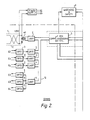
- FIG. 2 shows a schematic block diagram of the local electronics unit of one actuator control lane only, but in practice each actuator (10 in Figure 1) will have four separate and identical control lanes and associated electronics, each lane being controlled by a separate flight control computer (FCC) 1.
- FCC flight control computer
- Each FCC 1 is responsive to various flight parameters and the pilot's controls (not shown) to produce an actuator demand signal in response to which the relevant actuator will move, for example, a wing flap.
- the FCCs 1 are located in a central fuselage bay of the aircraft whilst the local electronics of each lane are located adjacent their associated actuator.
- the local electronics of each lane may be regarded as having two parts; one for communications ("comms") and the other for control and monitoring of the actuator. Both parts are provided in an electronics unit at the actuator, and linked to the FCC by means of a twin screened cable (11 in Figure 1(a)) comprising a combined serial digital comms link for bi-directional data signals and dc power and return.
- the bi-directional serial digital comms signals are superimposed on a +28V dc power line by means of transformers at each end of the screen cable (11) one of which is shown at 14 Fig 2.
- the FCC acts as the comms link master providing actuator demand data at a rate of between 80Hz and 3KHz.
- the local FCC actuator link electronics also includes a universal asynchronous receiver/transmitter (UART) 2. Status information is transmitted back to the FCC automatically after each data word is received or upon FCC request as will be discussed hereinafter.
- UART universal asynchronous receiver/transmitter
- the comms circuitry also includes six opto-isolators 3, for electrical isolation, connected in transmitter/receiver pairs to each of the other lanes. Each receiver and transmitter opto-isolator of a pair is connected to corresponding opto-isolators for transmission and reception respectively in the other three lane's electronic units.
- UARTs 4 three for receiving from and one for the transmission
- UARTs 4 are connected to the opto-isolators as shown to provide asynchronous unidirectional serial interlane data transmission on a internal communications bus 12.
- This interlane communication permits voter/monitor algorithms to be implemented in a comms microprocessor 5.
- BIT built-in-testing
- the control and monitoring part of the local electronics includes a digital signal control microprocessor 6 (DSP).
- DSP digital signal control microprocessor 6
- the control microprocessor 6 receives as input, via the comms microprocessor 5, actuator demand signals from the FCC and actuator data from the other 3 lanes (averaged or disregarded as necessary by interlane algorithms by the comms microprocessor).
- the actuator 10 includes a ram controlled by an electro-hydraulic spool valve 13, operated by a torque motor 14.
- the control microprocessor 6 produces a torque current demand as a pulse width modulated (PWM) signal scaled by the valve of the +28dc voltage.
- PWM pulse width modulated
- This demand signal is fed to a drive circuit (CCT) and a Mosfet 'H' bridge 7 which in turn controls the current in the windings 41 of the torque motor 14.
- Each actuator control lane includes three sets of feedback data; (i) torque winding current, (ii) spool valve position, and (iii) ram position.
- the torque winding current is sensed, then filtered and amplified in a unit 21 before being digitised and multiplexed by a multiplexer and a 12 bit analogue-to-digital unit 8 with digitised spool valve and ram position data.
- the spool valve and ram positions are determined by respective linear variable differential transformers, (LVDT) 15, 16.
- a common oscillator 17 drives the excitation windings of the spool valve and ram LVDTs is 15, 16.
- the LVDT outputs on windings 19 are phase sensitive rectified (PSR) and filtered in PSR and filter units 20 before being digitised and multiplexed in unit 8 with the torque winding current signal.
- PSR phase sensitive rectified
- filter units 20 before being digitised and multiplexed in unit 8 with the torque winding current signal.
- This digitised feedback data from lane one is then supplied to the comms microprocessor 5 where it is averaged with the digitised feed back data received via UARTs from other lanes by means of interlane algorithms and supplied as digital ram position data to the FCC 1 via the bus 12, UART 2 and link 11.
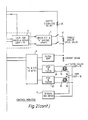
- the first stage controls the position of the spool in the main electro-hydraulic valve and includes the spool valve LUDT 15 and associated PSR and filter 20, this is referred to as the inner loop;
- the second stage referred to as the outer loop includes the RAM LVDT 16 and associate PBR and filter unit 20 and controls the position of the ram of the actuator.
- a ram position demand from the FCC is compared with the actual ram position (outer loop) and any difference creates a ram position error signal which is then used as a position input demand to the inner loop to move the spool valve in the correct direction so as to reduce the ram position error to zero, and hence to move the ram to the position demanded.
- the inner loop compares its position demand derived from the outer loop position error with the spool position and any difference drives the torque motor which moves the spool in the appropriate direction to reduce this error to zero. It will be seen that apart from the transmission of the initial position demand signal from the FCC the outer and inner loop feedback operations are confined to the local electronics at the actuator. In contrast prior art actuator control systems included the FCC in these loops with the consequent necessity for sending a plurality of feedback signals over a long multi-cable connection between FCC and actuator.
- the inner loop must have a faster response (and therefore higher bandwidth) than the outer loop for system stability.
- the outer loop has been controlled digitally while the inner loop was analogue - this was because the higher bandwidth required for the inner loop was easier to obtain by analogue rather than digital techniques.
- actuator control locally a considerable overhead is removed from the FCC and both inner and outer control loops can be performed digitally with one microprocessor. Digital control provides more consistent control from lane to lane and allows for their interchangeability.
- the bandwidth of the servo must be less than one half of the digital iteration rate (this is the Nyquist Sampling Theorem) to avoid aliasing. Additionally anti-aliasing filters are used with a sharp cut-off prior to digitising the position feedback signals such that the remaining LVDT carrier signal and hf noise is less than the lower side band of the analogue-to-digital converter.
- the iteration rate for the outer loop is at least 80Hz (12.5ms), and that of the inner loop is at least 320Hz (3.125ms).
- the inner loop spool position LVDT signal must be digitised every 3.125ms.
- This signal is passed between lanes, consolidated within each lane, then compared with outer loop error value and the difference value used as an input to the inner loop, then the control law calculations are performed to produce an output signal. Consolidation of the inner loop spool position is advantageous in producing equal current drive in the four separate torque motor coils, and in the event of a single lane failure the three remaining lanes share the additional burden equally.
- a watchdog 9 may be provided for both the comms and control microprocessors.
- the watchdog comprises logic and counters driven by a separate clock such that if the microprocessors halt or jump to a false memory location then a safety relay 30 (normally energised) will be de-energised and interrupts the drive signal to the torque motor 14.
- the watchdog clock can be monitored by the microprocessors and fail action taken if this exceeds some defined limits.
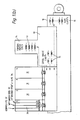
- Figure 1a and 1b shows a possible physical arrangement of the local control electronics on an actuator, in perspective and schematic sectional views respectively.
- each lane includes a replanable electronics module 31.
- Each module is identical and can be replaced without affecting the remaining lanes.
- Each module may include three boards 32, 33, 34 for, respectively, communications and power supply (PS), control microprocessor and watchdog, and H-bridge, phase sensitive rectifiers and A/D converter.
- PS communications and power supply
- the torque motor coils, spool valve and ram LVDTs are disposed separately from the modules but adjacent and connected thereto.
- Each lane also includes a connector 35 for the FCC link 11.
- fibre optics can be used; for example, one twin cable for dc power and return and two optical fibres (or a single multi mode optical fibre) for digital communications.
- the mounting of the modular on the actuator may be by any suitable arrangement, but it may be necessary to provide some form of thermal insulation between the modules and the actuator since the oil in the latter may reach temperatures as high as 130°C.
- the control electronics for each lane may be disposed not on the actuator but closely adjacent to it.
Landscapes
- Engineering & Computer Science (AREA)
- Power Engineering (AREA)
- Microelectronics & Electronic Packaging (AREA)
- Aviation & Aerospace Engineering (AREA)
- Radar, Positioning & Navigation (AREA)
- Remote Sensing (AREA)
- Physics & Mathematics (AREA)
- General Physics & Mathematics (AREA)
- Automation & Control Theory (AREA)
- Selective Calling Equipment (AREA)
- Feedback Control In General (AREA)
Applications Claiming Priority (2)
| Application Number | Priority Date | Filing Date | Title |
|---|---|---|---|
| GB8914450 | 1989-06-23 | ||
| GB898914450A GB8914450D0 (en) | 1989-06-23 | 1989-06-23 | Actuator control system |
Publications (2)
| Publication Number | Publication Date |
|---|---|
| EP0404223A2 true EP0404223A2 (fr) | 1990-12-27 |
| EP0404223A3 EP0404223A3 (fr) | 1992-05-06 |
Family
ID=10658946
Family Applications (1)
| Application Number | Title | Priority Date | Filing Date |
|---|---|---|---|
| EP19900201511 Withdrawn EP0404223A3 (fr) | 1989-06-23 | 1990-06-12 | Système de contrôle des actionneurs |
Country Status (2)
| Country | Link |
|---|---|
| EP (1) | EP0404223A3 (fr) |
| GB (1) | GB8914450D0 (fr) |
Cited By (6)
| Publication number | Priority date | Publication date | Assignee | Title |
|---|---|---|---|---|
| WO1996014610A1 (fr) * | 1994-11-07 | 1996-05-17 | Alliedsignal Inc. | Dispositif de commande insensible aux defaillances et destine a un appareil a moteur electrique |
| EP0835048A2 (fr) * | 1996-10-05 | 1998-04-08 | Bodenseewerk Gerätetechnik GmbH | Boítier pour un système à plusieurs canaux |
| EP1061269A3 (fr) * | 1999-06-16 | 2003-10-22 | EADS Deutschland GmbH | Procédé et dispositif pour la détection de l'opération défectueuse d'un actionneur de positionnement |
| WO2006130274A1 (fr) * | 2005-05-31 | 2006-12-07 | The Boeing Company | Actionneurs lineaires electrochimiques a commande directe |
| FR2897483A1 (fr) * | 2006-02-10 | 2007-08-17 | Kinetic Systems Sa | Actionneur lineaire electrique compact et etanche |
| CN113359803A (zh) * | 2021-07-08 | 2021-09-07 | 沃飞长空科技(成都)有限公司 | 无人机执行机构的总线控制装置、无人机及控制系统 |
Citations (5)
| Publication number | Priority date | Publication date | Assignee | Title |
|---|---|---|---|---|
| EP0128740A1 (fr) * | 1983-06-09 | 1984-12-19 | Applied Power Inc. | Régulateur de pression |
| EP0212462A2 (fr) * | 1985-08-30 | 1987-03-04 | Bso Steuerungstechnik Gmbh | Circuit d'amplificateur pour électro-aimants de valves proportionnelles ou de servo-valves |
| EP0251535A2 (fr) * | 1986-06-20 | 1988-01-07 | Gec-Marconi (Holdings) Limited | Systèmes d'actionnement redondants en parallèle |
| EP0260985A2 (fr) * | 1986-09-19 | 1988-03-23 | The Garrett Corporation | Dispositif d'asservissement hydraulique à commande électrique |
| EP0313899A2 (fr) * | 1987-10-27 | 1989-05-03 | The Boeing Company | Système de contrôle de vol à deux contrôleurs doubles agissant sur un vérin double |
-
1989
- 1989-06-23 GB GB898914450A patent/GB8914450D0/en active Pending
-
1990
- 1990-06-12 EP EP19900201511 patent/EP0404223A3/fr not_active Withdrawn
Patent Citations (5)
| Publication number | Priority date | Publication date | Assignee | Title |
|---|---|---|---|---|
| EP0128740A1 (fr) * | 1983-06-09 | 1984-12-19 | Applied Power Inc. | Régulateur de pression |
| EP0212462A2 (fr) * | 1985-08-30 | 1987-03-04 | Bso Steuerungstechnik Gmbh | Circuit d'amplificateur pour électro-aimants de valves proportionnelles ou de servo-valves |
| EP0251535A2 (fr) * | 1986-06-20 | 1988-01-07 | Gec-Marconi (Holdings) Limited | Systèmes d'actionnement redondants en parallèle |
| EP0260985A2 (fr) * | 1986-09-19 | 1988-03-23 | The Garrett Corporation | Dispositif d'asservissement hydraulique à commande électrique |
| EP0313899A2 (fr) * | 1987-10-27 | 1989-05-03 | The Boeing Company | Système de contrôle de vol à deux contrôleurs doubles agissant sur un vérin double |
Non-Patent Citations (2)
| Title |
|---|
| IEEE NAECON 1989 vol. 1, 22-26 May 1989, pages 338-345, Dayton Convention Center; R.J. MCLAUGHLIN et al.: "F/A-18 Aileron Smart Servoactuator" * |
| NEW ELECTRONICS vol. 20, no. 19, 29 September 1987, pages 43-48, London, GB; K.S. SNELLING et al.: "Flight control-implementing of active systems" * |
Cited By (10)
| Publication number | Priority date | Publication date | Assignee | Title |
|---|---|---|---|---|
| WO1996014610A1 (fr) * | 1994-11-07 | 1996-05-17 | Alliedsignal Inc. | Dispositif de commande insensible aux defaillances et destine a un appareil a moteur electrique |
| US5670856A (en) * | 1994-11-07 | 1997-09-23 | Alliedsignal Inc. | Fault tolerant controller arrangement for electric motor driven apparatus |
| EP0835048A2 (fr) * | 1996-10-05 | 1998-04-08 | Bodenseewerk Gerätetechnik GmbH | Boítier pour un système à plusieurs canaux |
| EP0835048A3 (fr) * | 1996-10-05 | 1998-05-27 | Bodenseewerk Gerätetechnik GmbH | Procédé pour la commutation d'appels aux abonnés déménagés avec préservation du numéro d'abonné |
| US5986210A (en) * | 1996-10-05 | 1999-11-16 | Bodenseewerk Geratetechnik Gmbh | Multi-channel housing |
| EP1061269A3 (fr) * | 1999-06-16 | 2003-10-22 | EADS Deutschland GmbH | Procédé et dispositif pour la détection de l'opération défectueuse d'un actionneur de positionnement |
| WO2006130274A1 (fr) * | 2005-05-31 | 2006-12-07 | The Boeing Company | Actionneurs lineaires electrochimiques a commande directe |
| US8266976B2 (en) | 2005-05-31 | 2012-09-18 | The Boeing Company | Direct drive electromechanical linear actuators |
| FR2897483A1 (fr) * | 2006-02-10 | 2007-08-17 | Kinetic Systems Sa | Actionneur lineaire electrique compact et etanche |
| CN113359803A (zh) * | 2021-07-08 | 2021-09-07 | 沃飞长空科技(成都)有限公司 | 无人机执行机构的总线控制装置、无人机及控制系统 |
Also Published As
| Publication number | Publication date |
|---|---|
| GB8914450D0 (en) | 1989-08-09 |
| EP0404223A3 (fr) | 1992-05-06 |
Similar Documents
| Publication | Publication Date | Title |
|---|---|---|
| EP3254960A1 (fr) | Architecture électrique de commande de becs/volets au moyen de capteurs et d'effecteurs intelligents | |
| CN102421667B (zh) | 根据集成模块化航空电子设备架构实现的分布式飞行控制系统 | |
| US20030128007A1 (en) | Motor controlling serial communication device and motor driver | |
| EP0754991B1 (fr) | Système de commande répartie tolérant des fautes | |
| US20120109424A1 (en) | Aircraft control system with integrated modular architecture | |
| CN103635386A (zh) | 电子同步襟翼系统 | |
| KR102301259B1 (ko) | 복수 축 모터 제어 시스템 | |
| EP0404223A2 (fr) | Système de contrôle des actionneurs | |
| EP3500486B1 (fr) | Unité de commande d'actionnement de secours pour commander un actionneur dédié à une surface donnée et son procédé d'utilisation | |
| CN102458995A (zh) | 具有增升系统的飞行器 | |
| EP1860821A1 (fr) | Réseau de fibre optique en plastique pour les unités de contrôle électronique et électronique de puissance dans les véhicules à compresseur d'alimentation | |
| EP2362534B1 (fr) | Systèmes et procédés permettant de contrôler un circuit électrique avec des contrôleurs séparés | |
| EP2472715A1 (fr) | Système de commande d'actionneurs et système d'actionneur | |
| Rubertus et al. | Electromechanical actuation technology for the all-electric aircraft | |
| US5333088A (en) | Data transmission system | |
| US20150314852A1 (en) | Electronic flap actuation system | |
| RU175530U1 (ru) | Высоконадёжный отказобезопасный электропривод реверсивного устройства | |
| US11528165B2 (en) | Remote sensor data acquisition | |
| CN115551751A (zh) | 飞行器刹车系统的分布式架构 | |
| US5204605A (en) | Position-controlled actuator | |
| EP2077477B1 (fr) | Concentrateur de données distant à sécurité intégrée | |
| CN100541363C (zh) | 用于冗余控制系统的外围单元 | |
| KR101658459B1 (ko) | 토크충돌 방지 기능을 가지는 항공기용 이중화 전기식 구동장치 | |
| US20230227174A1 (en) | Simplex flight control computer to be used in a flight control system | |
| EP1454198B1 (fr) | Servocontroleur passif apres panne |
Legal Events
| Date | Code | Title | Description |
|---|---|---|---|
| PUAI | Public reference made under article 153(3) epc to a published international application that has entered the european phase |
Free format text: ORIGINAL CODE: 0009012 |
|
| 17P | Request for examination filed |
Effective date: 19900620 |
|
| AK | Designated contracting states |
Kind code of ref document: A2 Designated state(s): DE ES FR GB IT SE |
|
| PUAL | Search report despatched |
Free format text: ORIGINAL CODE: 0009013 |
|
| AK | Designated contracting states |
Kind code of ref document: A3 Designated state(s): DE ES FR GB IT SE |
|
| RAP3 | Party data changed (applicant data changed or rights of an application transferred) |
Owner name: BRITISH AEROSPACE PUBLIC LIMITED COMPANY |
|
| STAA | Information on the status of an ep patent application or granted ep patent |
Free format text: STATUS: THE APPLICATION IS DEEMED TO BE WITHDRAWN |
|
| 18D | Application deemed to be withdrawn |
Effective date: 19921107 |