EP0403257B1 - High pressure transducer - Google Patents
High pressure transducer Download PDFInfo
- Publication number
- EP0403257B1 EP0403257B1 EP90306447A EP90306447A EP0403257B1 EP 0403257 B1 EP0403257 B1 EP 0403257B1 EP 90306447 A EP90306447 A EP 90306447A EP 90306447 A EP90306447 A EP 90306447A EP 0403257 B1 EP0403257 B1 EP 0403257B1
- Authority
- EP
- European Patent Office
- Prior art keywords
- pressure
- piston
- inlet
- fluid
- pressure transducer
- Prior art date
- Legal status (The legal status is an assumption and is not a legal conclusion. Google has not performed a legal analysis and makes no representation as to the accuracy of the status listed.)
- Expired - Lifetime
Links
Images


Classifications
-
- G—PHYSICS
- G01—MEASURING; TESTING
- G01L—MEASURING FORCE, STRESS, TORQUE, WORK, MECHANICAL POWER, MECHANICAL EFFICIENCY, OR FLUID PRESSURE
- G01L9/00—Measuring steady of quasi-steady pressure of fluid or fluent solid material by electric or magnetic pressure-sensitive elements; Transmitting or indicating the displacement of mechanical pressure-sensitive elements, used to measure the steady or quasi-steady pressure of a fluid or fluent solid material, by electric or magnetic means
- G01L9/0041—Transmitting or indicating the displacement of flexible diaphragms
- G01L9/0072—Transmitting or indicating the displacement of flexible diaphragms using variations in capacitance
- G01L9/0075—Transmitting or indicating the displacement of flexible diaphragms using variations in capacitance using a ceramic diaphragm, e.g. alumina, fused quartz, glass
-
- G—PHYSICS
- G01—MEASURING; TESTING
- G01L—MEASURING FORCE, STRESS, TORQUE, WORK, MECHANICAL POWER, MECHANICAL EFFICIENCY, OR FLUID PRESSURE
- G01L19/00—Details of, or accessories for, apparatus for measuring steady or quasi-steady pressure of a fluent medium insofar as such details or accessories are not special to particular types of pressure gauges
- G01L19/14—Housings
-
- G—PHYSICS
- G01—MEASURING; TESTING
- G01L—MEASURING FORCE, STRESS, TORQUE, WORK, MECHANICAL POWER, MECHANICAL EFFICIENCY, OR FLUID PRESSURE
- G01L9/00—Measuring steady of quasi-steady pressure of fluid or fluent solid material by electric or magnetic pressure-sensitive elements; Transmitting or indicating the displacement of mechanical pressure-sensitive elements, used to measure the steady or quasi-steady pressure of a fluid or fluent solid material, by electric or magnetic means
- G01L9/0089—Transmitting or indicating the displacement of pistons by electrical, electromechanical, magnetic or electromagnetic means
Definitions
- This invention is related to US-A-4 888 662 published 19,12,89 (EP-A2-403256 published 19,12,90) for HIGH PRESSURE PACKAGE FOR PRESSURE TRANSDUCERS of Robert P. Bishop.
- This invention relates to a packaging technique for pressure transducers and, more specifically, to such packaging for pressure transducers capable of measuring high pressures in the range of up to about 35 Megapascals (5000 psi).
- Pressure sensors containing pressure transducers are well known, typical such systems being described in U.S Letters Patent Nos. 4,716,492 and 4,774,626.
- Pressure transducers of the prior art have generally been fabricated by providing a pressure sensing module including an electronic circuit having a variable capacitor responsive to fluid pressure.
- the electronic circuit sensed the capacitance of the capacitor and provided an output through a plastic electrical connector indicative of the sensed pressure.
- the transducer elements were arranged such that a metal cup assembly having an opening or fluid pressure inlet at one end thereof to receive the fluid under pressure to be measured also included therein the pressure sensing module.
- the pressure sensing module was spaced from the inlet by a gasket or O-ring, the electronic circuit and connector also being contained within the metal cup. The parts were held together within the metal cup by crimping the metal cup over the plastic connector, the latter being used as a support member.
- the above described pressure transducer provided highly satisfactory results when operated in the low to moderate pressure ranges of up to 3.5 to 4.2 Megapascals (500 to 600 psi).
- the above described pressure transducers tended to fail. There were several points of failure, these being mainly from the inability of the plastic connector to support the high pressures to which it was being subjected. More specifically, the crimp at the metal cup was unable to retain the electrical connector crimped thereunder with the result that the connector was moved out of the cup and caused a failure of the transducer.
- a pressure sensor for measuring the pressure of a viscous polymer during an injection moulding operation.
- the sensor has a housing having a recess within which, mounted on a stub, is a piezoelectric element.
- a force derived from the pressure of the polymer is applied to the piezoelectric element via a steel block which fits on the housing having at one end a tubular part in which is received the stub and the piezoelectric element.
- the other end of the steel block is flush with the opening of recess in the housing.
- Around the block there is a small gap between the steel block and the housing through which the very viscous polymer does not penetrate significantly during the short duration of the moulding operation.
- a pressure sensor having a housing having a recess within which there are, mounted on a stub, two piezoelectric elements separated by a rigid mass.
- a force presumably derived from a fluid under pressure, is transmitted to the piezoelectric elements via a block which has at one end a tubular part containing the stub, piezoelectric elements and rigid mass.
- the tubular part of the block fits on to the housing.
- the other end of the block is flush with the opening of the recess in the housing and there is a gap around the block between the block and the housing.
- a pressure sensor having a housing having a recess and a first membrane mounted across the opening of the recess.
- the first membrane is displaced in response to the pressure of a fluid.
- the force is transmitted from the first membrane to a second membrane via a push rod.
- a strain gauge On the surface of the second membrane is mounted a strain gauge for giving an indication of the pressure of the fluid.
- the above described problem of the prior art is materially minimized and there is provided a high pressure transducer package wherein the pressures and stresses encountered within the package interior are substantially lower than those encountered in the above described prior art.
- a pressure transducer comprising: a housing having a high pressure fluid inlet, a pressure sensing element disposed within said housing, and a piston disposed in said fluid inlet and being sealingly, slidably movable therein in response to fluid pressure in said inlet to cause a force or a pressure to be applied to said pressure sensing element said piston serving to isolate said pressure sensing element from the fluid in said inlet.
- a piston or transfer pin in the fluid inlet wherein the total inlet pressure is applied against one end of the pin.
- the other end of the pin impinges against the pressure sensing element to transfer the pressure of the inlet fluid thereto.
- the inlet fluid does not reach the interior of the package, no pressure or stress therefrom is applied to the package or sealing elements within the package.
- the geometry is such that lower forces are transmitted throughout the package by the sensing element.
- a piston or transfer pin is placed in the fluid inlet whereby the inlet fluid impinges against one end thereof.
- This pressure is transferred to the pressure transducer either as in the first embodiment or via a liquid disposed between the opposing end of the piston and the pressure transducer.
- the piston in this embodiment has a larger diameter at the end thereof contacting either the pressure transducer or the liquid than it has at the end thereof contacting the inlet fluid. This causes a reduction in the pressure within the package and in the pressure applied to the pressure transducer since the latter pressure is applied over a larger area.
- the liquid provides for uniform application of the pressure from the piston to the pressure transducer along the entire area of contact therewith.
- a constant diameter piston or transfer pin is placed in the fluid inlet with inlet fluid impinging on one end thereof.
- the other end of the piston is positioned against a diaphragm having a substantially larger surface area than either end of the piston.
- a silicone gel, elastomer or other flowable material which is unaffected by the pressures involved is positioned between the diaphragm and the pressure transducer and retained thereat by a back-up ring or seal which forms an enclosure with the diaphragm and the pressure transducer.
- the pressures encountered within the package are materially lower than the pressure at the package inlet, the flowable material providing for uniform application of the pressure from the diaphragm along the entire area thereof.
- FIGURE 1 there is shown a high pressure transducer package 1 in accordance with one embodiment of the above noted application.
- the package includes an outer metal can or cap 3 having a pressure inlet 5 at one surface thereof and a pressure sensing module 7 within the can separated from the inlet by a rigid back-up ring 33 and a less rigid O-ring 9 to prevent the O-ring from movement between the sensing element 7 and the can 3.
- Electronic circuitry 11 is positioned in contact with the module 7 and is otherwise surrounded by a plastic electrical connector 13 having a flange portion 15 over which the can 3 is crimped.
- An environmental sealant 17 is positioned at the junction of the can 3 and the connector 13 to prevent contaminants from travelling between the can and connector to the electronic circuitry 11.
- the pressure sensing module 7 is composed of a pair of ceramic layers 19 and 21 which are spaced from each other, each layer having an electrically conductive coating thereon on opposing surfaces to form a capacitor.
- the layer 19 receives the force of fluid entering the pressure inlet 5 thereon and, operating as a diaphragm, varies the distance between electrically conductive coatings forming the capacitor to vary the capacitance of the capacitor as a function of applied pressure.
- a support ring 31 capable of withstanding pressures in the range of up to about 35 Megapascals (5000 psi) is disposed between the pressure sensing module 7 and the electrical connector 13 to isolate the electrical connector and the electronic circuitry 11 from the high pressure applied at the pressure inlet 5.
- the can 3 is crimped over both the support ring 31 as well as the flange 15 of the connector 13.
- FIGURE 2 there is shown a first embodiment of a system in accordance with the present invention for minimizing the pressures encountered at the interior of the transducer package.
- the transducer package is identical to that of FIGURE 1 except that there is provided a piston or transfer pin 35 in the fluid inlet 5 wherein the total inlet pressure is applied against one end of the pin. The other end of the pin 35 impinges against the pressure sensing element 19 to transfer the pressure in the inlet fluid thereto.
- the transfer pin 35 may include two or more sets of grooves in which are positioned O-rings 37 with or without back-up rings to seal the interior of the package from the fluid inlet 5.
- a vent to the package exterior can be provided in place of the O-rings 37 or in addition thereto to vent inlet fluid which bypasses the exterior surface of the piston 35 from entering the package interior.
- inlet fluid does not reach the interior of the package, no pressure or stress therefrom is applied to the package or sealing elements within the package. The stresses applied to the package elements are reduced and result only from the force applied by the piston or transfer pin on the pressure sensing element.
- the space between the piston 35 and the layer 19 can be filled with a fluid to provide lubrication and thereby reduce hysteresis.
- FIGURE 3 there is shown a second embodiment of the invention, wherein, again, a piston or transfer pin 41 is placed in the fluid inlet 5 whereby the inlet fluid impinges against one end thereof.
- This pressure is transferred to the pressure transducer layer 19 either as in the first embodiment or via a liquid 43 disposed in a pressure cavity between the opposing end of the piston 41 and the pressure transducer layer 19.
- the piston 41 in this embodiment has a larger diameter portion 45 at the end thereof contacting either the pressure transducer layer 19 or the liquid 43 than at the end 47 contacting the inlet fluid. This causes a reduction in the pressure applied to the pressure transducer since the pressure is applied over a larger area.
- the liquid provides for uniform application of the pressure from the piston to the pressure transducer along the entire area of contact therewith.
- O-rings 49 with or without back-up rings are provided in grooves in the piston 51 as in the embodiment of FIGURE 2 for the same reason.
- FIGURE 4 there is shown a third embodiment of the invention wherein a constant diameter piston or transfer pin 51 is placed in the fluid inlet 5 with inlet fluid impinging on one end thereof.
- the other end of the piston is placed against a thin metal diaphragm 53 having a substantially larger surface area than either end of the piston.
- a silicone gel, elastomer or other flowable material 55 which is unaffected by the pressures involved is positioned between the diaphragm 53 and the pressure transducer layer 19 and is maintained between the diaphragm and the layer 19 by a back-up ring 59 of rigid material, such as, for example, polytetrafluoroethylene or of a non-rigid seal material.
- the pressures encountered within the package 1 are materially lower than the pressure at the package inlet, the flowable material 55 providing for uniform application of the pressure from the diaphragm 53 along the entire area thereof.
- one or more O-rings 57 are provided for the same reasons as discussed above with reference to FIGURES 2 and 3.
Landscapes
- Physics & Mathematics (AREA)
- General Physics & Mathematics (AREA)
- Electromagnetism (AREA)
- Chemical & Material Sciences (AREA)
- Engineering & Computer Science (AREA)
- Ceramic Engineering (AREA)
- Measuring Fluid Pressure (AREA)
Description
- This invention is related to US-A-4 888 662 published 19,12,89 (EP-A2-403256 published 19,12,90) for HIGH PRESSURE PACKAGE FOR PRESSURE TRANSDUCERS of Robert P. Bishop.
- This invention relates to a packaging technique for pressure transducers and, more specifically, to such packaging for pressure transducers capable of measuring high pressures in the range of up to about 35 Megapascals (5000 psi).
- Pressure sensors containing pressure transducers are well known, typical such systems being described in U.S Letters Patent Nos. 4,716,492 and 4,774,626.
- Pressure transducers of the prior art have generally been fabricated by providing a pressure sensing module including an electronic circuit having a variable capacitor responsive to fluid pressure. The electronic circuit sensed the capacitance of the capacitor and provided an output through a plastic electrical connector indicative of the sensed pressure. The transducer elements were arranged such that a metal cup assembly having an opening or fluid pressure inlet at one end thereof to receive the fluid under pressure to be measured also included therein the pressure sensing module. The pressure sensing module was spaced from the inlet by a gasket or O-ring, the electronic circuit and connector also being contained within the metal cup. The parts were held together within the metal cup by crimping the metal cup over the plastic connector, the latter being used as a support member.
- The above described pressure transducer provided highly satisfactory results when operated in the low to moderate pressure ranges of up to 3.5 to 4.2 Megapascals (500 to 600 psi). However, when subjected to pressures at the pressure inlet in the range of about 21 to 35 Megapascals (3000 to 5000 psi) and up, the above described pressure transducers tended to fail. There were several points of failure, these being mainly from the inability of the plastic connector to support the high pressures to which it was being subjected. More specifically, the crimp at the metal cup was unable to retain the electrical connector crimped thereunder with the result that the connector was moved out of the cup and caused a failure of the transducer. A further point of failure was the plastic connector itself which tended to shear or compress and release the gasket or O-ring under the high pressure and release the fluid under pressure from the interior of the pressure transducer. It is therefore clear that the prior art pressure transducer of the type described hereinabove was incapable of reliable operation in a high pressure environment.
- The above described problem of the prior art was materially improved in accordance with the packaging techniques described in the above mentioned US-A-4 888 662 wherein the pressure sensing element is isolated from the connector by being disposed in all metal surrounded cavity whereby the plastic connector is separated from the pressure transducer element and is not bearing the loads produced by the high pressure fluid. This is accomplished by a metal member disposed between the pressure sensing element and the plastic connector whereby the high pressures encountered by the pressure transducer are never applied to the plastic connector. However, though the pressure transducers of this application provide highly satisfactory results, there remains the problem that the internal pressures within the transducer are equal to the applied high pressure to be measured. This places all structural members of the package as well as the seal mechanism in a highly stressed state. It is therefore apparent that any diminution of the stresses applied within the package will result in improved transducer life and will materially relieve those problems caused by such internal stresses which have previously been minimized by costly design measures.
- On pages 194-195 of the book "Piezoelektrische Meßtechnik" by Tichy and Gautschi published by Springer-Verlag in 1980 there is disclosed a pressure sensor for measuring the pressure of a viscous polymer during an injection moulding operation. The sensor has a housing having a recess within which, mounted on a stub, is a piezoelectric element. A force derived from the pressure of the polymer is applied to the piezoelectric element via a steel block which fits on the housing having at one end a tubular part in which is received the stub and the piezoelectric element. The other end of the steel block is flush with the opening of recess in the housing. Around the block there is a small gap between the steel block and the housing through which the very viscous polymer does not penetrate significantly during the short duration of the moulding operation.
- At pages 61-62 of the book "Technische Druck- und Kraftmessung" edited by Prof. Dr.-Ing. K.W. Bonfig and published by Expert Verlag in 1988, there is disclosed a pressure sensor having a housing having a recess within which there are, mounted on a stub, two piezoelectric elements separated by a rigid mass. A force, presumably derived from a fluid under pressure, is transmitted to the piezoelectric elements via a block which has at one end a tubular part containing the stub, piezoelectric elements and rigid mass. The tubular part of the block fits on to the housing. The other end of the block is flush with the opening of the recess in the housing and there is a gap around the block between the block and the housing.
- In Figure 4 of the European Patent Application that was published under the number 0,145,146 there is disclosed a pressure sensor having a housing having a recess and a first membrane mounted across the opening of the recess. The first membrane is displaced in response to the pressure of a fluid. The force is transmitted from the first membrane to a second membrane via a push rod. On the surface of the second membrane is mounted a strain gauge for giving an indication of the pressure of the fluid.
- In accordance with the present invention, the above described problem of the prior art is materially minimized and there is provided a high pressure transducer package wherein the pressures and stresses encountered within the package interior are substantially lower than those encountered in the above described prior art.
- According to the present invention there is provided a pressure transducer comprising:
a housing having a high pressure fluid inlet,
a pressure sensing element disposed within said housing, and
a piston disposed in said fluid inlet and being sealingly, slidably movable therein in response to fluid pressure in said inlet to cause a force or a pressure to be applied to said pressure sensing element
said piston serving to isolate said pressure sensing element from the fluid in said inlet. - In a first embodiment of the invention, there is provided a piston or transfer pin in the fluid inlet wherein the total inlet pressure is applied against one end of the pin. The other end of the pin impinges against the pressure sensing element to transfer the pressure of the inlet fluid thereto. However, since the inlet fluid does not reach the interior of the package, no pressure or stress therefrom is applied to the package or sealing elements within the package. The geometry is such that lower forces are transmitted throughout the package by the sensing element.
- In accordance with a second embodiment of the invention, again, a piston or transfer pin is placed in the fluid inlet whereby the inlet fluid impinges against one end thereof. This pressure is transferred to the pressure transducer either as in the first embodiment or via a liquid disposed between the opposing end of the piston and the pressure transducer. In addition, the piston in this embodiment has a larger diameter at the end thereof contacting either the pressure transducer or the liquid than it has at the end thereof contacting the inlet fluid. This causes a reduction in the pressure within the package and in the pressure applied to the pressure transducer since the latter pressure is applied over a larger area. The liquid provides for uniform application of the pressure from the piston to the pressure transducer along the entire area of contact therewith.
- In accordance with a third embodiment of the invention, a constant diameter piston or transfer pin is placed in the fluid inlet with inlet fluid impinging on one end thereof. The other end of the piston is positioned against a diaphragm having a substantially larger surface area than either end of the piston. A silicone gel, elastomer or other flowable material which is unaffected by the pressures involved is positioned between the diaphragm and the pressure transducer and retained thereat by a back-up ring or seal which forms an enclosure with the diaphragm and the pressure transducer. In this manner, the pressures encountered within the package are materially lower than the pressure at the package inlet, the flowable material providing for uniform application of the pressure from the diaphragm along the entire area thereof.
-
- FIGURE 1 is a cross sectional view of a high pressure transducer package in accordance with the above noted US-A-4 888 662;
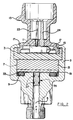
- FIGURE 2 is a cross sectional view of a high pressure transducer package in accordance with a first embodiment of the present invention;
- FIGURE 3 is a cross sectional view of a high pressure transducer package in accordance with a second embodiment of the present invention; and
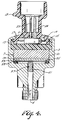
- FIGURE 4 is a cross sectional view of a high pressure transducer package in accordance with a third embodiment of the present invention.
- Referring first to FIGURE 1, there is shown a high pressure transducer package 1 in accordance with one embodiment of the above noted application. The package includes an outer metal can or
cap 3 having a pressure inlet 5 at one surface thereof and apressure sensing module 7 within the can separated from the inlet by a rigid back-upring 33 and a less rigid O-ring 9 to prevent the O-ring from movement between thesensing element 7 and thecan 3. Electronic circuitry 11 is positioned in contact with themodule 7 and is otherwise surrounded by a plasticelectrical connector 13 having aflange portion 15 over which thecan 3 is crimped. Anenvironmental sealant 17 is positioned at the junction of thecan 3 and theconnector 13 to prevent contaminants from travelling between the can and connector to the electronic circuitry 11. Threeterminals pressure sensing module 7 is composed of a pair ofceramic layers layer 19 receives the force of fluid entering the pressure inlet 5 thereon and, operating as a diaphragm, varies the distance between electrically conductive coatings forming the capacitor to vary the capacitance of the capacitor as a function of applied pressure. Asupport ring 31, capable of withstanding pressures in the range of up to about 35 Megapascals (5000 psi) is disposed between thepressure sensing module 7 and theelectrical connector 13 to isolate the electrical connector and the electronic circuitry 11 from the high pressure applied at the pressure inlet 5. Thecan 3 is crimped over both thesupport ring 31 as well as theflange 15 of theconnector 13. - Referring now to FIGURE 2, there is shown a first embodiment of a system in accordance with the present invention for minimizing the pressures encountered at the interior of the transducer package. In all instances herein, like numbers represent the same or similar elements. Accordingly, as can be seen with respect to FIGURE 2, the transducer package is identical to that of FIGURE 1 except that there is provided a piston or
transfer pin 35 in the fluid inlet 5 wherein the total inlet pressure is applied against one end of the pin. The other end of thepin 35 impinges against thepressure sensing element 19 to transfer the pressure in the inlet fluid thereto. Thetransfer pin 35 may include two or more sets of grooves in which are positioned O-rings 37 with or without back-up rings to seal the interior of the package from the fluid inlet 5. As an alternative, not shown, a vent to the package exterior can be provided in place of the O-rings 37 or in addition thereto to vent inlet fluid which bypasses the exterior surface of thepiston 35 from entering the package interior. However, since the inlet fluid does not reach the interior of the package, no pressure or stress therefrom is applied to the package or sealing elements within the package. The stresses applied to the package elements are reduced and result only from the force applied by the piston or transfer pin on the pressure sensing element. If desired, the space between thepiston 35 and thelayer 19 can be filled with a fluid to provide lubrication and thereby reduce hysteresis. - With reference to FIGURE 3, there is shown a second embodiment of the invention, wherein, again, a piston or transfer pin 41 is placed in the fluid inlet 5 whereby the inlet fluid impinges against one end thereof. This pressure is transferred to the
pressure transducer layer 19 either as in the first embodiment or via a liquid 43 disposed in a pressure cavity between the opposing end of the piston 41 and thepressure transducer layer 19. In addition, the piston 41 in this embodiment has alarger diameter portion 45 at the end thereof contacting either thepressure transducer layer 19 or the liquid 43 than at theend 47 contacting the inlet fluid. This causes a reduction in the pressure applied to the pressure transducer since the pressure is applied over a larger area. The liquid provides for uniform application of the pressure from the piston to the pressure transducer along the entire area of contact therewith. As can be seen in FIGURE 3, O-rings 49 with or without back-up rings are provided in grooves in the piston 51 as in the embodiment of FIGURE 2 for the same reason. - With reference to FIGURE 4, there is shown a third embodiment of the invention wherein a constant diameter piston or transfer pin 51 is placed in the fluid inlet 5 with inlet fluid impinging on one end thereof. The other end of the piston is placed against a thin metal diaphragm 53 having a substantially larger surface area than either end of the piston. A silicone gel, elastomer or other
flowable material 55 which is unaffected by the pressures involved is positioned between the diaphragm 53 and thepressure transducer layer 19 and is maintained between the diaphragm and thelayer 19 by a back-up ring 59 of rigid material, such as, for example, polytetrafluoroethylene or of a non-rigid seal material. In this manner, the pressures encountered within the package 1 are materially lower than the pressure at the package inlet, theflowable material 55 providing for uniform application of the pressure from the diaphragm 53 along the entire area thereof. Again, one or more O-rings 57 are provided for the same reasons as discussed above with reference to FIGURES 2 and 3.
Claims (7)
- A pressure transducer comprising:
a housing (3) having a high pressure fluid inlet (5),
a pressure sensing element (7) disposed within said housing, and
a piston (35, 45, 51) disposed in said fluid inlet (5) and being sealingly (27, 49, 51), slidably movable therein in response to fluid pressure in said inlet to cause a force or a pressure to be applied to said pressure sensing element (7)
said piston serving to isolate said pressure sensing element from the fluid in said inlet (5). - A pressure transducer as set forth in claim 1 wherein said piston (35) includes at least one annular groove on the surface thereof coaxial with the axis of said piston and either an O-ring (35, 49 or 57) or an O-ring and a back-up ring disposed in said groove to act as a seal.
- A pressure transducer as set forth in claim 1 or 2 wherein the area of the surface of said piston communicating with the entrance to said fluid inlet is smaller than the area of the surface of said piston remote from said fluid inlet.
- A pressure transducer as set forth in claim 3 further including a liquid pressure transferring medium (43) disposed between said pressure sensing element and said surface of said piston remote from said fluid inlet.
- A pressure transducer as set forth in claim 1 or 2 further including a diaphragm (53) abutting the surface of said piston remote from the entrance to said fluid inlet and a liquid pressure transferring medium (55) disposed between said diaphragm and said pressure sensing element.
- A pressure transducer as set forth in claim 5 wherein said pressure transferring medium (55) is a silicone gel or an elastomer.
- A pressure transducer as set forth in claim 5 or 6 further including either a back-up ring or a seal (59) disposed between said diaphragm (53) and said pressure sensing element (7) so as to contain said pressure transferring medium in a predetermined enclosure within a region defined by said back-up ring or seal, said pressure sensing element and said diaphragm.
Applications Claiming Priority (2)
| Application Number | Priority Date | Filing Date | Title |
|---|---|---|---|
| US07/366,045 US5043841A (en) | 1989-06-13 | 1989-06-13 | High pressure transducer package |
| US366045 | 1999-08-02 |
Publications (3)
| Publication Number | Publication Date |
|---|---|
| EP0403257A2 EP0403257A2 (en) | 1990-12-19 |
| EP0403257A3 EP0403257A3 (en) | 1991-07-31 |
| EP0403257B1 true EP0403257B1 (en) | 1994-03-02 |
Family
ID=23441446
Family Applications (1)
| Application Number | Title | Priority Date | Filing Date |
|---|---|---|---|
| EP90306447A Expired - Lifetime EP0403257B1 (en) | 1989-06-13 | 1990-06-13 | High pressure transducer |
Country Status (4)
| Country | Link |
|---|---|
| US (1) | US5043841A (en) |
| EP (1) | EP0403257B1 (en) |
| JP (1) | JPH0394132A (en) |
| DE (1) | DE69006925T2 (en) |
Cited By (5)
| Publication number | Priority date | Publication date | Assignee | Title |
|---|---|---|---|---|
| US5712428A (en) * | 1995-08-01 | 1998-01-27 | Endress & Hauser Gmbh | Pressure sensor with a solid to minimize temperature-related measurement error |
| WO2002031459A1 (en) * | 2000-10-10 | 2002-04-18 | Endress + Hauser Gmbh + Co. Kg | Membrane pressure monitor sensor comprising a seal with a counter-deformation spring washer |
| DE10353323A1 (en) * | 2003-11-14 | 2005-06-23 | Vega Grieshaber Kg | Sensor, in particular pressure sensor with a sensor device fastening device |
| US7448274B2 (en) | 2003-07-29 | 2008-11-11 | Endress + Hauser Conducta Gesellschaft Fur Mess- U. Regeltechnik Mbh + Co. Kg | Pressure sensor having a pressure measuring cell with a platform and a measuring membrane |
| DE102014207394B4 (en) | 2013-04-18 | 2019-05-09 | Ifm Electronic Gmbh | pressure sensor |
Families Citing this family (15)
| Publication number | Priority date | Publication date | Assignee | Title |
|---|---|---|---|---|
| JPH0640830U (en) * | 1991-06-26 | 1994-05-31 | 応用計測工業株式会社 | Pressure gauge |
| US5315877A (en) * | 1993-02-19 | 1994-05-31 | Kavlico Corporation | Low cost versatile pressure transducer |
| US5827972A (en) * | 1993-11-02 | 1998-10-27 | Texas Instruments Incorporated | High pressure sensor apparatus with low cost compact packaging system |
| US5436795A (en) * | 1994-03-28 | 1995-07-25 | Texas Instruments Incorporated | Pressure transducer apparatus and method for making same |
| US5822173A (en) * | 1996-05-29 | 1998-10-13 | Texas Instruments Incorporated | Condition responsive electrical apparatus having improved low cost housing |
| US6055864A (en) * | 1998-04-14 | 2000-05-02 | Mannesmann Vdo Ag | Pressure sensor and method for its production |
| JP3498665B2 (en) * | 1999-03-12 | 2004-02-16 | 株式会社デンソー | Pressure detecting device and method of manufacturing the same |
| US7197937B2 (en) * | 2005-01-26 | 2007-04-03 | Sensata Technologies, Inc. | Hermetic pressure sensing device |
| JP4727369B2 (en) * | 2005-09-29 | 2011-07-20 | 株式会社イトーキ | desk |
| DE102009031482A1 (en) * | 2009-06-19 | 2011-01-05 | Lischka, Peter | Autofrettage - pressure transducer |
| DE102011077868A1 (en) * | 2011-06-21 | 2012-12-27 | Robert Bosch Gmbh | Pressure sensor arrangement for detecting a pressure of a fluid medium in a measuring space |
| JP5594541B2 (en) | 2012-02-09 | 2014-09-24 | Smc株式会社 | Pressure detector |
| DE102013225335A1 (en) * | 2013-12-10 | 2014-11-13 | Siemens Aktiengesellschaft | Pressure transmitter for process instrumentation |
| DE102017119358A1 (en) * | 2017-08-24 | 2019-02-28 | Endress+Hauser SE+Co. KG | Modular field device |
| DE102018127014A1 (en) * | 2018-10-30 | 2020-04-30 | Endress+Hauser Conducta Gmbh+Co. Kg | Process connection for a sensor and manufacturing process of the process connection |
Citations (1)
| Publication number | Priority date | Publication date | Assignee | Title |
|---|---|---|---|---|
| EP0145146A2 (en) * | 1983-09-19 | 1985-06-19 | Ford Motor Company Limited | Combustion pressure sensor |
Family Cites Families (7)
| Publication number | Priority date | Publication date | Assignee | Title |
|---|---|---|---|---|
| GB1075355A (en) * | 1963-02-08 | 1967-07-12 | Fairey Eng | Improvements relating to excess pressure protective devices for pressure gauges etc |
| US4414851A (en) * | 1981-08-28 | 1983-11-15 | Motorola, Inc. | Gauge pressure sensor |
| US4425799A (en) * | 1982-06-03 | 1984-01-17 | Kavlico Corporation | Liquid capacitance pressure transducer technique |
| JPS6013235A (en) * | 1983-07-01 | 1985-01-23 | Kinseki Kk | Pressure sensor |
| GB2154323B (en) * | 1984-02-14 | 1987-02-18 | Plessey Co Plc | Pressure sensor |
| US4774626A (en) * | 1986-05-05 | 1988-09-27 | Texas Instruments Incorporated | Pressure sensor with improved capacitive pressure transducer |
| US4888662A (en) * | 1988-12-08 | 1989-12-19 | Texas Instruments Incorporated | High pressure package for pressure transducers |
-
1989
- 1989-06-13 US US07/366,045 patent/US5043841A/en not_active Expired - Lifetime
-
1990
- 1990-06-12 JP JP2153821A patent/JPH0394132A/en active Pending
- 1990-06-13 EP EP90306447A patent/EP0403257B1/en not_active Expired - Lifetime
- 1990-06-13 DE DE69006925T patent/DE69006925T2/en not_active Expired - Fee Related
Patent Citations (1)
| Publication number | Priority date | Publication date | Assignee | Title |
|---|---|---|---|---|
| EP0145146A2 (en) * | 1983-09-19 | 1985-06-19 | Ford Motor Company Limited | Combustion pressure sensor |
Non-Patent Citations (2)
| Title |
|---|
| J. Tichy and G. Gautschi, "Piezoelektrische Messtechnik", (DE), 1980, pages 194, 195 * |
| K. W. Bonfig et al: "Technische Druck- und Kraftmessung", (DE), 1988, pages 61, 62 * |
Cited By (6)
| Publication number | Priority date | Publication date | Assignee | Title |
|---|---|---|---|---|
| US5712428A (en) * | 1995-08-01 | 1998-01-27 | Endress & Hauser Gmbh | Pressure sensor with a solid to minimize temperature-related measurement error |
| WO2002031459A1 (en) * | 2000-10-10 | 2002-04-18 | Endress + Hauser Gmbh + Co. Kg | Membrane pressure monitor sensor comprising a seal with a counter-deformation spring washer |
| US7448274B2 (en) | 2003-07-29 | 2008-11-11 | Endress + Hauser Conducta Gesellschaft Fur Mess- U. Regeltechnik Mbh + Co. Kg | Pressure sensor having a pressure measuring cell with a platform and a measuring membrane |
| DE10353323A1 (en) * | 2003-11-14 | 2005-06-23 | Vega Grieshaber Kg | Sensor, in particular pressure sensor with a sensor device fastening device |
| US6955088B2 (en) | 2003-11-14 | 2005-10-18 | Thomas Kopp | Sensor, particularly a pressure sensor with a sensor fastening device |
| DE102014207394B4 (en) | 2013-04-18 | 2019-05-09 | Ifm Electronic Gmbh | pressure sensor |
Also Published As
| Publication number | Publication date |
|---|---|
| DE69006925D1 (en) | 1994-04-07 |
| EP0403257A3 (en) | 1991-07-31 |
| JPH0394132A (en) | 1991-04-18 |
| DE69006925T2 (en) | 1994-06-09 |
| US5043841A (en) | 1991-08-27 |
| EP0403257A2 (en) | 1990-12-19 |
Similar Documents
| Publication | Publication Date | Title |
|---|---|---|
| US5043841A (en) | High pressure transducer package | |
| EP0403256B1 (en) | Making an O-Ring/Back-up Seal for High Pressure Transducers | |
| EP0372988B1 (en) | High pressure package for pressure transducers | |
| US4507973A (en) | Housing for capacitive pressure sensor | |
| US5000047A (en) | Pressure sensor | |
| US5712428A (en) | Pressure sensor with a solid to minimize temperature-related measurement error | |
| US5001934A (en) | Solid state pressure sensor | |
| US5827972A (en) | High pressure sensor apparatus with low cost compact packaging system | |
| EP1883798B1 (en) | Pressure sensor using compressible sensor body | |
| DE4335588C2 (en) | Pressure sensor | |
| US5165281A (en) | High pressure capacitive transducer | |
| EP1065488B1 (en) | Relative pressure sensor | |
| EP1335195B1 (en) | Insert-molded assembly of a pressure sensor with a pressure vessel | |
| US4262540A (en) | Pressure measuring device | |
| US4722227A (en) | High pressure sensor | |
| US6272927B1 (en) | Hermetically sealed pressure sensing device | |
| US6223603B1 (en) | Capacitive pressure transducer having reduced output error | |
| US5111699A (en) | Sensor for measuring the pressure of a medium | |
| US6516670B2 (en) | Pressure sensor | |
| US4770045A (en) | Pressure sensor | |
| EP4261516B1 (en) | Methods and apparatuses for providing freeze resistant sensing assembly | |
| US6598482B2 (en) | Overload resistant differential pressure sensor | |
| CA1232773A (en) | Adhesive joint for diaphragm to sensor connection in pressure transducers | |
| EP0100221A2 (en) | Fluid pressure sensitive construction and method of making the same | |
| CN113091992B (en) | High-range differential pressure sensor |
Legal Events
| Date | Code | Title | Description |
|---|---|---|---|
| PUAI | Public reference made under article 153(3) epc to a published international application that has entered the european phase |
Free format text: ORIGINAL CODE: 0009012 |
|
| AK | Designated contracting states |
Kind code of ref document: A2 Designated state(s): DE FR GB IT NL |
|
| PUAL | Search report despatched |
Free format text: ORIGINAL CODE: 0009013 |
|
| AK | Designated contracting states |
Kind code of ref document: A3 Designated state(s): DE FR GB IT NL |
|
| 17P | Request for examination filed |
Effective date: 19911119 |
|
| 17Q | First examination report despatched |
Effective date: 19921230 |
|
| GRAA | (expected) grant |
Free format text: ORIGINAL CODE: 0009210 |
|
| ITF | It: translation for a ep patent filed | ||
| AK | Designated contracting states |
Kind code of ref document: B1 Designated state(s): DE FR GB IT NL |
|
| REF | Corresponds to: |
Ref document number: 69006925 Country of ref document: DE Date of ref document: 19940407 |
|
| ET | Fr: translation filed | ||
| PLBE | No opposition filed within time limit |
Free format text: ORIGINAL CODE: 0009261 |
|
| STAA | Information on the status of an ep patent application or granted ep patent |
Free format text: STATUS: NO OPPOSITION FILED WITHIN TIME LIMIT |
|
| 26N | No opposition filed | ||
| ITTA | It: last paid annual fee | ||
| REG | Reference to a national code |
Ref country code: GB Ref legal event code: IF02 |
|
| PGFP | Annual fee paid to national office [announced via postgrant information from national office to epo] |
Ref country code: GB Payment date: 20030501 Year of fee payment: 14 |
|
| PGFP | Annual fee paid to national office [announced via postgrant information from national office to epo] |
Ref country code: NL Payment date: 20030513 Year of fee payment: 14 |
|
| PGFP | Annual fee paid to national office [announced via postgrant information from national office to epo] |
Ref country code: FR Payment date: 20030602 Year of fee payment: 14 |
|
| PGFP | Annual fee paid to national office [announced via postgrant information from national office to epo] |
Ref country code: DE Payment date: 20030630 Year of fee payment: 14 |
|
| PG25 | Lapsed in a contracting state [announced via postgrant information from national office to epo] |
Ref country code: GB Free format text: LAPSE BECAUSE OF NON-PAYMENT OF DUE FEES Effective date: 20040613 |
|
| PG25 | Lapsed in a contracting state [announced via postgrant information from national office to epo] |
Ref country code: NL Free format text: LAPSE BECAUSE OF NON-PAYMENT OF DUE FEES Effective date: 20050101 Ref country code: DE Free format text: LAPSE BECAUSE OF NON-PAYMENT OF DUE FEES Effective date: 20050101 |
|
| GBPC | Gb: european patent ceased through non-payment of renewal fee |
Effective date: 20040613 |
|
| PG25 | Lapsed in a contracting state [announced via postgrant information from national office to epo] |
Ref country code: FR Free format text: LAPSE BECAUSE OF NON-PAYMENT OF DUE FEES Effective date: 20050228 |
|
| NLV4 | Nl: lapsed or anulled due to non-payment of the annual fee |
Effective date: 20050101 |
|
| REG | Reference to a national code |
Ref country code: FR Ref legal event code: ST |
|
| PG25 | Lapsed in a contracting state [announced via postgrant information from national office to epo] |
Ref country code: IT Free format text: LAPSE BECAUSE OF NON-PAYMENT OF DUE FEES;WARNING: LAPSES OF ITALIAN PATENTS WITH EFFECTIVE DATE BEFORE 2007 MAY HAVE OCCURRED AT ANY TIME BEFORE 2007. THE CORRECT EFFECTIVE DATE MAY BE DIFFERENT FROM THE ONE RECORDED. Effective date: 20050613 |