EP0403174B1 - Differential amplifying circuit operable at high speed - Google Patents
Differential amplifying circuit operable at high speed Download PDFInfo
- Publication number
- EP0403174B1 EP0403174B1 EP90306261A EP90306261A EP0403174B1 EP 0403174 B1 EP0403174 B1 EP 0403174B1 EP 90306261 A EP90306261 A EP 90306261A EP 90306261 A EP90306261 A EP 90306261A EP 0403174 B1 EP0403174 B1 EP 0403174B1
- Authority
- EP
- European Patent Office
- Prior art keywords
- fet
- source
- voltage
- fets
- drain
- Prior art date
- Legal status (The legal status is an assumption and is not a legal conclusion. Google has not performed a legal analysis and makes no representation as to the accuracy of the status listed.)
- Expired - Lifetime
Links
- 230000005669 field effect Effects 0.000 claims description 3
- 238000010586 diagram Methods 0.000 description 6
- 230000035945 sensitivity Effects 0.000 description 3
- JBRZTFJDHDCESZ-UHFFFAOYSA-N AsGa Chemical compound [As]#[Ga] JBRZTFJDHDCESZ-UHFFFAOYSA-N 0.000 description 2
- 229910001218 Gallium arsenide Inorganic materials 0.000 description 2
- 238000010276 construction Methods 0.000 description 2
- 230000001737 promoting effect Effects 0.000 description 2
- 239000004065 semiconductor Substances 0.000 description 2
- 230000033228 biological regulation Effects 0.000 description 1
- 150000001875 compounds Chemical class 0.000 description 1
- 230000007423 decrease Effects 0.000 description 1
- 230000006866 deterioration Effects 0.000 description 1
- 230000000694 effects Effects 0.000 description 1
- 238000004088 simulation Methods 0.000 description 1
- 239000000758 substrate Substances 0.000 description 1
- 230000001131 transforming effect Effects 0.000 description 1
Images



Classifications
-
- H—ELECTRICITY
- H03—ELECTRONIC CIRCUITRY
- H03F—AMPLIFIERS
- H03F3/00—Amplifiers with only discharge tubes or only semiconductor devices as amplifying elements
- H03F3/45—Differential amplifiers
- H03F3/45071—Differential amplifiers with semiconductor devices only
- H03F3/45076—Differential amplifiers with semiconductor devices only characterised by the way of implementation of the active amplifying circuit in the differential amplifier
- H03F3/45376—Differential amplifiers with semiconductor devices only characterised by the way of implementation of the active amplifying circuit in the differential amplifier using junction FET transistors as the active amplifying circuit
- H03F3/45381—Long tailed pairs
- H03F3/45385—Non-folded cascode stages
-
- H—ELECTRICITY
- H03—ELECTRONIC CIRCUITRY
- H03F—AMPLIFIERS
- H03F2203/00—Indexing scheme relating to amplifiers with only discharge tubes or only semiconductor devices as amplifying elements covered by H03F3/00
- H03F2203/45—Indexing scheme relating to differential amplifiers
- H03F2203/45024—Indexing scheme relating to differential amplifiers the differential amplifier amplifying transistors are cascode coupled transistors
-
- H—ELECTRICITY
- H03—ELECTRONIC CIRCUITRY
- H03F—AMPLIFIERS
- H03F2203/00—Indexing scheme relating to amplifiers with only discharge tubes or only semiconductor devices as amplifying elements covered by H03F3/00
- H03F2203/45—Indexing scheme relating to differential amplifiers
- H03F2203/45186—Indexing scheme relating to differential amplifiers the differential amplifier contains clamping components in the load circuit
-
- H—ELECTRICITY
- H03—ELECTRONIC CIRCUITRY
- H03F—AMPLIFIERS
- H03F2203/00—Indexing scheme relating to amplifiers with only discharge tubes or only semiconductor devices as amplifying elements covered by H03F3/00
- H03F2203/45—Indexing scheme relating to differential amplifiers
- H03F2203/45244—Indexing scheme relating to differential amplifiers the differential amplifier contains one or more explicit bias circuits, e.g. to bias the tail current sources, to bias the load transistors
-
- H—ELECTRICITY
- H03—ELECTRONIC CIRCUITRY
- H03F—AMPLIFIERS
- H03F2203/00—Indexing scheme relating to amplifiers with only discharge tubes or only semiconductor devices as amplifying elements covered by H03F3/00
- H03F2203/45—Indexing scheme relating to differential amplifiers
- H03F2203/45641—Indexing scheme relating to differential amplifiers the LC being controlled, e.g. by a signal derived from a non specified place in the dif amp circuit
Definitions
- the present invention relates to a differential amplifying circuit of the type using field effect transistors (FETs) and applicable to semiconductor integrated circuits or similar circuitry. More particularly, the present invention is concerned with a differential amplifying FET circuit with a common source connection circuit formed on a compound semiconductor (for example, gallium arsenide) substrate.
- FETs field effect transistors
- a differential amplifying circuit as described above has been proposed in various forms in the past. To better understand the present invention, a brief reference will be made to some prior art differential amplifying circuits.
- FIG. 1 shows a prior art differential amplifying circuit with input terminals 10 and 12.
- An input voltage VI and a reference voltage VR1 are applied to the input terminals 10 and 12, respectively.
- a differential input section 14 is connected to the input terminals 10 and 12 and has a pair of enhancement type FETs 16 and 18.
- the FET 16 is turned on and off by the input voltage VI, while the FET 18 is turned on and off by the reference voltage VR1.
- the FETS 16 and 18 have drains connected to a load section 20, and sources connected to a negative power source voltage VSS via an enhancement type FET 22. This FET 22 plays the role of a constant current source.
- the load section 20 has a depletion type FET 24 connected between a positive power source voltage VDD and the drain of the FET 16, and a depletion type FET 26 connected between the power source voltage VDD and the drain of the FET 18.
- the FETs 24 and 26 serve as load elements.
- Output terminals 28 and 30 on which output voltages outl and out2 appear, respectively, are connected to the drains of the FETs 16 and 1 8, respectively.
- the reference numeral 32 designates an input terminal assigned to a reference voltage VR2.
- the prior art differential amplifying circuit having the above construction uses the FETs 24 and 26 as load elements and selects a saturation drain current of such elements which is substantially one half the current of the constant current source 22.
- a drawback with this configuration is that when the input voltage VI having a great amplitude arrives, the resultant output waveform appears stepwise and is thereby degraded.
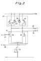
- FIG. 2 shows another prior art differential amplifying circuit which is disclosed in JP-B-89007522.
- the same components are designated by like reference numerals, and redundant description will be avoided for simplicity.
- the circuit of FIG. 2 is distinguishable over the circuit of FIG. 1 in that depletion type FETs 40 and 42 are provided in place of the load FETs 24 and 26, and that Zener diodes 44 and 46 are respectively connected in parallel with the FETs 40 and 42 in opposite direction.
- the reference numerals 47 and 48 designate input terminals assigned to input voltages VI1 and VI2, respectively.
- a differential amplifier circuit which comprises a first input port for receiving an input voltage; a first field effect transistor having a drain, a source and a gate which is responsive to said input voltage to control conduction between said drain and said source; a second FET having a drain, a source and a gate which is responsive to a first reference voltage to control conduction between said drain and said source of said second FET, said source of said second FET being connected to said source of said first FET; a constant current source connected to said sources of said first and second FETs for supplying a constant current from said sources of said first and second FETs to a low potential power source; a third FET having a drain connected to a high potential power source and having a source connected to a first output port to act as a
- a differential amplifying circuit as defined above with reference to an IEEE conference paper, is characterized in that said third FET has a gate connected to said first node which is connected to said drain of said first FET and said fourth FET has a gate connected to said second node which is connected to said drain of said second FET.
- the third and fourth FETs each is implemented as a depletion type FET.
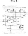
- FIG. 3 shows a differential amplifying circuit embodying the present invention.
- the circuit has an input terminal 110 to which an input voltage VI is applied, and a differential input section 112 connected to the input terminal 110.
- the differential input section 112 is made up of enhancement type FETs 114 and 116.
- the enhancement type FET 114 is connected to the input terminal 110, while the enhancement type FET 116 is connected to a node N1 on which a first reference voltage VR1 appears.
- Resistors 118 and 120 are connected between the node NI and a high potential power source VDD and between the node NI and a low potential power source VSS, respectively.
- the drains of the FETs 114 and 116 are connected at nodes N2 and N3, respectively, to a load section 122 and a switch section 124.
- the sources of the FETs 114 and 116 are connected to the low potential power source VSS via an enhancement type FET 126 which plays the role of a constant current source.
- the load section 122 has a depletion type FET 128 which is connected to the node N2 at the gate thereof, and a depletion type FET/30 connected to the node N3 at the gate thereof.
- the FETs 128 and 130 serve as load elements.
- the source voltage VDD is connected to the drains of the FETs 128 and 130, while the switch section 124 is connected to the sources of the FETs 128 and 130.
- the switch section 124 has an enhancement type FET 132 whose drain is connected to the source of the FET 128, and an enhancement type FET 134 whose drain is connected to the source of the FET 130.
- the gates of the FETs 132 and 134 are connected commonly to a node N4 which is held at a second reference voltage VR2.
- a depletion type FET 136 adapted for a load is connected between the node N4 and the power source voltage VDD.
- the drain of the FET 132 is connected to an output terminal 138 assigned to an output voltage OUTl, while the drain of the FET 134 is connected to an output terminal 140 assigned to an output voltage OUT2.
- a depletion type FET 142 and an enhancement type FET 144 generate a constant voltage.
- the FET or constant current source 126 causes a constant current to flow at all times between the drain and the source thereof on the basis of the constant voltage which is generated by the FETs 142 and 144 as mentioned above.
- the gate of the FET 126 is connected to the gates of the FETs 142 and 144 which are in turn connected to a node N5.
- the FETs 142 and 144 are connected in series between the node N4 and the power source voltage VSS via the node N5.
- the differential input section 112 serves the function of a circuit for controlling the FETs 114 and 116 on and off by detecting a difference between the reference voltage VR1 and the input voltage VI.
- the FETs 132 and 134 perform switching operations on the basis of the reference voltage VR2 so as to change the state of current flow sharply, whereby the logical levels of the output terminals 138 and 140 are reproduced surely and rapidly.
- the FET 128 since the gate voltage of the FET 128 is equal to the voltage on the node N2, the FET 128 is turned off when the voltage on the node N2 decreases beyond a predetermined value. Then, a current which does not exceed the capacity of the FET 126 flows into the amplifying circuit via the output terminal 138 because the FETs 114 and 132 have been turned on.
- the current coming in via the output terminal 138 turns off the FET 116 and thereby increases the voltage on the node N3.
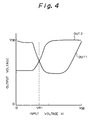
- the FET 124 is turned off with the result that the output voltage OUT2 is turned from the low level to the high level, as shown in FIG. 4.
- the gate voltage of the FET 130 is equal to the voltage appearing on the node N3, the FET 130 turns off at the instant when the voltage on the node N3 rises above a predetermined value.
- the FETs 116 and 134 are in their OFF state, the current flows out to a succeeding circuit, not shown, via the output terminal 140 within the range which the FET 130 accommodates.
- the FET 114 On the turn of the input voltage VI from a high level to a low level, the FET 114 is turned off to in turn increase the voltage appearing on the node N2.
- the FET 132 When the voltage on the node N2 increases nearly to the second reference voltage VR2, the FET 132 is turned off and, therefore, the output voltage OUT1 is caused into a high level, as shown in FIG. 4. Since the gate voltage of the FET 128 is equal to the voltage on the node N2, the FET 128 is turned on when the voltage on the node N2 increases beyond a predetermined value. At this time, the FETs 114 and 132 are in their OFF state, so that the current flows out to the succeeding circuit via the output terminal 138 within the range determined by the capacity of the FET 128.
- the FET 116 On the outflow of the current as stated above, the FET 116 is turned on to lower the voltage on the node N3.
- the FET 134 is turned on to cause the output voltage OU2 into a low level, as shown in FIG. 4. Since the gate voltage of the FET 130 is equal to the voltage appearing on the node N3, the FET 130 is turned off when the voltage on the node N3 drops beyond a predetermined value. At this moment, the FETs 116 and 134 remain turned off and, hence, a current flows into the amplifying circuit via the output terminal 140 within the range determined by the drive capacity of the FET 126.
- FIG. 5 is a graph comparing the operation of the illustrative embodiment with that of the prior art circuitry of FIG. 1. Specifically, the curves shown in FIG. 5 simulate the relationship between the current and output voltage on the output terminal and the time, on the assumption that the constant current sources of the circuits shown in FIGS. 1 and 3 are the same, and that the load acting on the output terminal is 0.3 picofarad.
- curves labeled X and Y are associated with the circuits of FIGS. 3 and 1, respectively.
- the operation X of the illustrative embodiment achieves greater incoming and outgoing currents than the operation Y of the prior art, because the FETs 128, 130, 132 and 134 turn on and off. Such incoming and outgoing currents allow the output voltage level to settle rapidly.
- an arrangement may be made such that the first reference voltage VR1 coincides with the center of the levels of the input voltage VI, and the second reference voltage VR2 coincides with the center of the logical amplitude levels which are determined by the current ratio in the conductive state of the FETs 114, 116, 128, 130 and 126. Then, the on-off operations of the FETs 128, 130, 132 and 134 serve to set cause the logical levels of the nodes N2 and N3 or those of the output terminals 138 and 140 to settle more rapidly. This is successful in further promoting high-speed operations and in increasing the sensitivity.
- the conduction of the FET 128 is controlled by the voltage appearing on the node N2, while the conduction of the FET 130 is controlled by the voltage appearing on the node N3.
- the FETs 128 and 130 serving as load elements are implemented as depletion type FETs the ON resistance of which is comparatively small, a great current can be fed to the succeeding circuit and, yet, the power consumption is reduced.
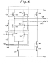
- FIG. 6 an alternative embodiment of the differential amplifying circuit in accordance with the present invention is shown.
- the same components as those shown in FIG. 3 are designated by like reference numerals, and redundant description will be avoided for simplicity.
- the circuit of FIG. 6 differs from the circuit of FIG. 3 in that the resistors 118 and 120 for generating the first reference voltage VR1 are omitted, and that an input voltage VI ⁇ opposite in phase to the input voltage VI coming in from the outside is applied to the gate of the FET 116. Specifically, the input voltage VI ⁇ is applied to a second input terminal 146.
- the alternative embodiment is essentially the same as the previous embodiment.
- FIG. 7 is a diagram showing an input circuit which is a specific application of the illustrative embodiments state above with reference to FIGS. 3 and 6.
- the same components are designated by like reference numerals, and redundant description will be avoided for simplicity.
- the input circuit has an input terminal 150 to which an input voltage VI is applied, and an output terminal 152.
- a differential amplifying circuit 154, a level shifting circuit 156, a differential amplifying circuit 158, and a level shifting circuit 160 are cascaded in this order between the input terminal 150 and the output terminal 152.
- the differential amplifying circuits 154 and 158 are implemented by the illustrative embodiments shown in FIGS. 3 and 6, respectively.
- the level shifting circuit 156 is made up of a series connection of normally OFF FETs 156a and 156b intervening between power source voltages VDD and VSS, and a series connection of normally OFF FETs 156c and 156d also intervening between the power source voltages VDD and VSS.
- the level shifting circuit 156 has a function of lowering the voltage to below the input voltage VI.
- the gates of the FETs 156a and 156c are respectively connected to the output voltages OUT1 and OUT2 of the differential amplifying circuit 154.
- the gates of the FETs 156b and 156d are connected to the gate of the FET 144 of the differential amplifier 154.
- the output voltage between the FETs 156a and 156b and the output voltage between the FETs 156c and 156d are connected to the differential amplifier 158, while the output voltage of the differential amplifier 158 is in turn connected to the level shifting circuit 160.
- the level shifting circuit 160 has an enhancement type FET 160a, a diode 160b for shifting the level, and a depletion type FET 160c adapted for a load.
- the FET 160a, diode 160b and FET 160c are connected in series between the power source voltages VDD and VSS. Also connected in series between the power source voltages VDD and VSS are a depletion type FET 160d, a diode 160e, and an enhancement type FET 160f.
- the level shifting circuit 160 is connected to the output terminal 152 between the diode 160e and the enhancement type FET 160f.
- the input circuit shown in FIG. 7 is implemented as an input level transforming circuit, and that it is used to transform a voltage level width from the ECL level (0.3 volt in peak-to-peak value) to the DCFL level (0.6 volt in peak-to-peak value) using gallium arsenide.
- a differential amplifying circuit in accordance with the present invention has a fifth switching FET connected between the first switching FET and the third load FET, and a sixth switching FET connected between the second switching FET and the fourth load FET.
- the fifth and sixth FETs are turned on and off to change the amount of current flow sharply, so that the logical levels of various nodes settle within a short period of time and, in addition, the sensitivity is enhanced.
- the conduction of the third FET and that of the fourth FET are controlled by voltages appearing on first and second nodes, respectively. Hence, even when a circuit having a great load capacitance is connected to the output side and requires a great current, a sufficient current is insured up to the limit which depends on the drive capacity of the load FETs and the supply capacity of a constant current source. This is successful in promoting rapid operations.
- the third and fourth FETs as depletion type FETs whose ON resistance is relatively small, it is possible to feed a great current to a succeeding circuit while achieving a power saving effect.
- the enhancement type FETs 114, 116, 132 and 134 of the illustrative embodiments may be replaced with depletion type FETs.
- the enhancement type FETs 114 and 116 are replaced with depletion type FETs, it is necessary to lower the reference voltage VR1 to a level at which the FETs 114 and 116 are operable.
- the enhancement type FET 126 serving as a constant current source may be replaced with a FET whose gate and source are short-circuited or even with a resistor.
Landscapes
- Engineering & Computer Science (AREA)
- Power Engineering (AREA)
- Logic Circuits (AREA)
- Amplifiers (AREA)
Description
- The present invention relates to a differential amplifying circuit of the type using field effect transistors (FETs) and applicable to semiconductor integrated circuits or similar circuitry. More particularly, the present invention is concerned with a differential amplifying FET circuit with a common source connection circuit formed on a compound semiconductor (for example, gallium arsenide) substrate.
- A differential amplifying circuit as described above has been proposed in various forms in the past. To better understand the present invention, a brief reference will be made to some prior art differential amplifying circuits.
- FIG. 1 shows a prior art differential amplifying circuit with
input terminals input terminals differential input section 14 is connected to theinput terminals enhancement type FETs FET 16 is turned on and off by the input voltage VI, while theFET 18 is turned on and off by the reference voltage VR1. The FETS 16 and 18 have drains connected to aload section 20, and sources connected to a negative power source voltage VSS via anenhancement type FET 22. This FET 22 plays the role of a constant current source. - The
load section 20 has adepletion type FET 24 connected between a positive power source voltage VDD and the drain of theFET 16, and adepletion type FET 26 connected between the power source voltage VDD and the drain of theFET 18. The FETs 24 and 26 serve as load elements.Output terminals FETs reference numeral 32 designates an input terminal assigned to a reference voltage VR2. - In operation, when the input voltage VI applied to the
input terminal 10 is higher than the reference voltage VR1, theFET 16 is turned on with the result that the potential at theoutput terminal 28 turns from a high level or "H" to a low level or "L". Then. a current flows into the amplifying circuit via theoutput terminal 28. This incoming current and the current from theload FET 24 join each other and flow together into the negative power source voltage VSS via the constantcurrent source 22. At this time, the potential at theoutput terminal 30 turns to a high level because the FET 18 remains in an OFF state. Consequently, a current flows out to a succeeding circuit, not shown, from the power source voltage VDD via theFET 26 andoutput terminal 30. - On the other hand, when an input voltage VI lower than the reference voltage VR1 arrives at the
input terminal 10, theFET 16 is turned off resulting in theoutput terminal 28 in a high level. As a result, a current flows out from the power source voltage VDD to the succeeding circuit via theFET 24 andoutput terminal 28. Since theFET 12 is in an ON state, the potential at theoutput terminal 30 turns from a high level to a low level with the result that a current flows into the amplifying circuit via theoutput terminal 30. This current and a current from theFET 26 join each other and flow together into the negative power source voltage VSS via theFET 18 and constantcurrent source 22. - The prior art differential amplifying circuit having the above construction uses the
FETs current source 22. A drawback with this configuration is that when the input voltage VI having a great amplitude arrives, the resultant output waveform appears stepwise and is thereby degraded. - FIG. 2 shows another prior art differential amplifying circuit which is disclosed in JP-B-89007522. In the figures, the same components are designated by like reference numerals, and redundant description will be avoided for simplicity. The circuit of FIG. 2 is distinguishable over the circuit of FIG. 1 in that
depletion type FETs load FETs diodes FETs reference numerals - In the circuitry shown in FIG. 2, when the voltage across the FET or
load diode FET - Specifically, when the
output terminal 28, for example, is caused into a low level, a discharge current flows into the amplifying circuit from a succeeding circuit, not shown. Since, the sum of the discharge current and the current from theload FET 40 constitutes the current of the constantcurrent source 22, the discharge current is limited by the current from theFET 40. On the other hand, when the potential at theoutput terminal 28 is turned from a low level to a high level, a charge current flows out to the succeeding circuit. At this time, the current from theload FET 40 is the charge current because theFET 16 is in an OFF state. Since the saturation drain current of theFET 40 is selected to be one half the current of the constantcurrent source 22, such a charge current is limited by the saturation drain current. In this manner, the discharge current from and the charge current to the succeeding circuit are limited, impeding the increase in the operating speed of the circuit. - In IEEE International Solid-state Circuits Conference, Vol. 28,February 1985, 32nd conf., pp 146-147, 327, NY, USA, "Operational Amplifiers and Voltage Regulation", D.C. Soo et al, a differential amplifier circuit is disclosed which comprises a first input port for receiving an input voltage; a first field effect transistor having a drain, a source and a gate which is responsive to said input voltage to control conduction between said drain and said source; a second FET having a drain, a source and a gate which is responsive to a first reference voltage to control conduction between said drain and said source of said second FET, said source of said second FET being connected to said source of said first FET; a constant current source connected to said sources of said first and second FETs for supplying a constant current from said sources of said first and second FETs to a low potential power source; a third FET having a drain connected to a high potential power source and having a source connected to a first output port to act as a load; a fourth FET having a drain connected to said high potential power source and having a source connected to a second output to act as a load; a fifth FET having a drain connected to said source of said third FET and a source connected to said first node, said fifth FET having a gate which is responsive to a second reference voltage to control conduction between said drain and said source of said fifth FET; and a sixth FET having a drain connected to said source of said fourth FET and having a source connected to said second node, said sixth FET having a gate which is connected to said gate of said fifth FET and which is responsive to said second reference voltage to control conduction between said drain and said source of said sixth FET, said second reference voltage being independent of the conduction of said first through sixth FETs.
- It is therefore an object of the present invention to provide a differential amplifying circuit which eliminates the drawbacks particular to the prior art as discussed above.
- It is another object of the present invention to provide a differential amplifying circuit which is operable at high speed.
- It is another object of the present invention to provide a differential amplifying circuit capable of feeding a great current as required by a succeeding circuit, while cutting down power consumption.
- In accordance with the present invention, a differential amplifying circuit, as defined above with reference to an IEEE conference paper, is characterized in that said third FET has a gate connected to said first node which is connected to said drain of said first FET and said fourth FET has a gate connected to said second node which is connected to said drain of said second FET.
- In a preferred embodiment of the present invention, the third and fourth FETs each is implemented as a depletion type FET.
- The objects and features of the present invention will become more apparent from the consideration of the following detailed description taken in conjunction with the accompanying drawings in which:
- FIG. 1 is a diagram showing a prior art differential amplifying circuit;
- FIG. 2 is a diagram showing another prior art differential amplifying circuit;
- FIG. 3 is a diagram representative of a differential amplifying circuit embodying the present invention;
- FIG. 4 is a graph demonstrating the operation of the illustrative embodiment shown in FIG. 3;
- FIG. 5 is a chart useful for understanding the difference in operation between the prior art circuit of FIG. 1 and the illustrative embodiment of FIG. 3;
- FIG. 6 is a diagram showing an alternative embodiment of the differential amplifying circuit in accordance with the present invention; and
- FIG. 7 is a diagram representative of a specific application of the illustrative embodiments.
- FIG. 3 shows a differential amplifying circuit embodying the present invention. As shown, the circuit has an
input terminal 110 to which an input voltage VI is applied, and adifferential input section 112 connected to theinput terminal 110. Thedifferential input section 112 is made up ofenhancement type FETs input terminal 110, while theenhancement type FET 116 is connected to a node N1 on which a first reference voltage VR1 appears.Resistors FETs load section 122 and aswitch section 124. The sources of the FETs 114 and 116 are connected to the low potential power source VSS via an enhancement type FET 126 which plays the role of a constant current source. - The
load section 122 has adepletion type FET 128 which is connected to the node N2 at the gate thereof, and a depletion type FET/30 connected to the node N3 at the gate thereof. The FETs 128 and 130 serve as load elements. The source voltage VDD is connected to the drains of theFETs switch section 124 is connected to the sources of theFETs - The
switch section 124 has anenhancement type FET 132 whose drain is connected to the source of the FET 128, and anenhancement type FET 134 whose drain is connected to the source of the FET 130. The gates of theFETs depletion type FET 136 adapted for a load is connected between the node N4 and the power source voltage VDD. The drain of theFET 132 is connected to anoutput terminal 138 assigned to an output voltage OUTl, while the drain of theFET 134 is connected to anoutput terminal 140 assigned to an output voltage OUT2. - A
depletion type FET 142 and anenhancement type FET 144 generate a constant voltage. The FET or constantcurrent source 126 causes a constant current to flow at all times between the drain and the source thereof on the basis of the constant voltage which is generated by theFETs FET 126 is connected to the gates of theFETs FETs - The
differential input section 112 serves the function of a circuit for controlling theFETs switching section 124, theFETs output terminals - The operation of the circuitry constructed as shown in FIG. 3 will be described with reference to the waveforms shown in FIG. 4. When the input voltage VI applied to the
input terminal 110 is higher than the reference voltage VR1, i.e., in a high level or "H", theFET 114 is turned on with the result that the current flowing between the drain and the source thereof is increased to in turn lower the voltage appearing on the node N2. As soon as the voltage on the node N2 is sufficiently lowered below the second reference voltage VR2, theFET 132 is turned on to increase the current flowing between the drain and the source thereof. As a result, the output voltage OUT1 is brought to a low level or "L", as shown in FIG. 4. In this instance, since the gate voltage of theFET 128 is equal to the voltage on the node N2, theFET 128 is turned off when the voltage on the node N2 decreases beyond a predetermined value. Then, a current which does not exceed the capacity of theFET 126 flows into the amplifying circuit via theoutput terminal 138 because theFETs - The current coming in via the
output terminal 138 turns off theFET 116 and thereby increases the voltage on the node N3. As the voltage on the node N3 rises nearly to the second reference voltage VR2, theFET 124 is turned off with the result that the output voltage OUT2 is turned from the low level to the high level, as shown in FIG. 4. Since the gate voltage of theFET 130 is equal to the voltage appearing on the node N3, theFET 130 turns off at the instant when the voltage on the node N3 rises above a predetermined value. Then, since theFETs output terminal 140 within the range which theFET 130 accommodates. - On the turn of the input voltage VI from a high level to a low level, the
FET 114 is turned off to in turn increase the voltage appearing on the node N2. When the voltage on the node N2 increases nearly to the second reference voltage VR2, theFET 132 is turned off and, therefore, the output voltage OUT1 is caused into a high level, as shown in FIG. 4. Since the gate voltage of theFET 128 is equal to the voltage on the node N2, theFET 128 is turned on when the voltage on the node N2 increases beyond a predetermined value. At this time, theFETs output terminal 138 within the range determined by the capacity of theFET 128. - On the outflow of the current as stated above, the
FET 116 is turned on to lower the voltage on the node N3. When the voltage on the node N3 is sufficiently lowered below the second reference voltage VR2, theFET 134 is turned on to cause the output voltage OU2 into a low level, as shown in FIG. 4. Since the gate voltage of theFET 130 is equal to the voltage appearing on the node N3, theFET 130 is turned off when the voltage on the node N3 drops beyond a predetermined value. At this moment, theFETs output terminal 140 within the range determined by the drive capacity of theFET 126. - The illustrative embodiment having the construction shown in FIG. 3 achieves various advantages, as follows.
- FIG. 5 is a graph comparing the operation of the illustrative embodiment with that of the prior art circuitry of FIG. 1. Specifically, the curves shown in FIG. 5 simulate the relationship between the current and output voltage on the output terminal and the time, on the assumption that the constant current sources of the circuits shown in FIGS. 1 and 3 are the same, and that the load acting on the output terminal is 0.3 picofarad. In FIG. 5, curves labeled X and Y are associated with the circuits of FIGS. 3 and 1, respectively. As shown, the operation X of the illustrative embodiment achieves greater incoming and outgoing currents than the operation Y of the prior art, because the
FETs - In the circuit shown in FIG. 3, an arrangement may be made such that the first reference voltage VR1 coincides with the center of the levels of the input voltage VI, and the second reference voltage VR2 coincides with the center of the logical amplitude levels which are determined by the current ratio in the conductive state of the
FETs FETs output terminals - The conduction of the
FET 128 is controlled by the voltage appearing on the node N2, while the conduction of theFET 130 is controlled by the voltage appearing on the node N3. Hence, even when a circuit having a great load capacitance is connected to the output side of the circuit shown in FIG. 3 and requires the latter to supply a great current thereto, a sufficient current is insured up to the limit which depends on the capacity of theFET 126. Therefore, the circuit is operable at high speed. - Since the
FETs - Referring to FIG. 6, an alternative embodiment of the differential amplifying circuit in accordance with the present invention is shown. In FIG. 6, the same components as those shown in FIG. 3 are designated by like reference numerals, and redundant description will be avoided for simplicity. The circuit of FIG. 6 differs from the circuit of FIG. 3 in that the
resistors 
FET 116. Specifically, the input voltage
second input terminal 146. Regarding the operation, the alternative embodiment is essentially the same as the previous embodiment. When the input voltage
FET 116 as mentioned, theFETs - FIG. 7 is a diagram showing an input circuit which is a specific application of the illustrative embodiments state above with reference to FIGS. 3 and 6. In the figures, the same components are designated by like reference numerals, and redundant description will be avoided for simplicity. As shown, the input circuit has an
input terminal 150 to which an input voltage VI is applied, and anoutput terminal 152. Adifferential amplifying circuit 154, alevel shifting circuit 156, adifferential amplifying circuit 158, and alevel shifting circuit 160 are cascaded in this order between theinput terminal 150 and theoutput terminal 152. Thedifferential amplifying circuits - The
level shifting circuit 156 is made up of a series connection of normallyOFF FETs OFF FETs level shifting circuit 156 has a function of lowering the voltage to below the input voltage VI. The gates of theFETs differential amplifying circuit 154. The gates of theFETs FET 144 of thedifferential amplifier 154. The output voltage between theFETs differential amplifier 158, while the output voltage of thedifferential amplifier 158 is in turn connected to thelevel shifting circuit 160. - The
level shifting circuit 160 has anenhancement type FET 160a, adiode 160b for shifting the level, and adepletion type FET 160c adapted for a load. TheFET 160a,diode 160b andFET 160c are connected in series between the power source voltages VDD and VSS. Also connected in series between the power source voltages VDD and VSS are adepletion type FET 160d, adiode 160e, and anenhancement type FET 160f. Thelevel shifting circuit 160 is connected to theoutput terminal 152 between thediode 160e and theenhancement type FET 160f. - Assume that the input circuit shown in FIG. 7 is implemented as an input level transforming circuit, and that it is used to transform a voltage level width from the ECL level (0.3 volt in peak-to-peak value) to the DCFL level (0.6 volt in peak-to-peak value) using gallium arsenide. Simulations were conducted by using the input circuit of FIG. 7 under particular characteristic conditions: gate length Lg = 1 micron, threshold voltage of depletion type FET Vtd = -819 millivolts, constant of depletion type FET Kd = 1.22 milliamperes per square volt, threshold volage of enhancement type FET Vte = +79 millivolts, and constant of enhancement type FET Ke = 2.10 milliamperes per square volt. It was found that the clock frequency under the above conditions is 2.5 gigahertz and, therefore, the input circuit is operable at high speed.
- In summary, a differential amplifying circuit in accordance with the present invention has a fifth switching FET connected between the first switching FET and the third load FET, and a sixth switching FET connected between the second switching FET and the fourth load FET. The fifth and sixth FETs are turned on and off to change the amount of current flow sharply, so that the logical levels of various nodes settle within a short period of time and, in addition, the sensitivity is enhanced.
- The conduction of the third FET and that of the fourth FET are controlled by voltages appearing on first and second nodes, respectively. Hence, even when a circuit having a great load capacitance is connected to the output side and requires a great current, a sufficient current is insured up to the limit which depends on the drive capacity of the load FETs and the supply capacity of a constant current source. This is successful in promoting rapid operations.
- Furthermore, by implementing the third and fourth FETs as depletion type FETs whose ON resistance is relatively small, it is possible to feed a great current to a succeeding circuit while achieving a power saving effect.
- While the present invention has been described with reference to the particular illustrative embodiments, it is not to be restricted by the embodiments but only by the appended claims. It is to be appreciated that those skilled in the art can change or modify the embodiments without departing from the scope of the present invention. For example, the
enhancement type FETs enhancement type FETs FETs FETs enhancement type FET 126 serving as a constant current source may be replaced with a FET whose gate and source are short-circuited or even with a resistor.
Claims (6)
- A differential amplifier circuit comprising:a first input port for receiving an input voltage;a first field effect transistor (FET) (114) having a drain, a source and a gate which is responsive to said input voltage (VI) to control conduction between said drain and said source;a second FET (116) having a drain, a source and a gate which is responsive to a first reference voltage (VRI) to control conduction between said drain and said source of said second FET (116), said source of said second FET (116) being connected to said source of said first FET (114);a constant current source (126) connected to said sources of said first and second FETs (114, 116) for supplying a constant current from said sources of said first and second FETs (114, 116) to a low potential power source (VSS);a third FET (128) having a drain connected to a high potential power source (VDD) and having a source connected to a first output port (OUT1) to act as a load;a fourth FET (130) having a drain connected to said high potential power source (VDD) and having a source connected to a second output (OUT2) to act as a load;a fifth FET (132) having a drain connected to said source of said third FET (128) and a source connected to said first node (N2), said fifth FET (132) having a gate which is responsive to a second reference voltage (VR2) to control conduction between said drain and said source of said fifth FET (132); anda sixth FET (134) having a drain connected to said source of said fourth FET (130) and having a source connected to said second node (N3), said sixth FET (134) having a gate which is connected to said gate of said fifth FET (132) and which is responsive to said second reference voltage (VR2) to control conduction between said drain and said source of said sixth FET (134), said second reference voltage (UR2) being independent of the conduction of said first through sixth FETs (114, 116, 128, 130, 132, 134), characterized in that said third FET (128) has a gate connected to a first node (N2) which is connected to said drain of said first FET (114) and said fourth FET (130) has a gate connected to a second node (N3) which is connected to said drain of said second FET (116).
- A circuit in accordance with claim 1, further comprising a second input port connected to said gate of said second FET (116) for receiving a voltage (V1) which is opposite in phase to said input voltage (V1) to provide said gate of said second FET (116) with first reference voltage (VR1).
- A circuit in accordance with claim 1, or 2, wherein said third and fourth FETs (128, 130) each comprises a depletion type FET.
- A circuit in accordance with claim 1, 2 or 3, wherein said first, second, fifth and sixth FETs (114, 116, 132, 134) each comprises an enhancement type FET.
- A circuit in accordance with claim 1, 2 or 3, wherein said first, second, fifth and sixth FETs (114, 116, 132, 134) each comprises a depletion type FET.
- A circuit in accordance with any preceding claim, wherein said constant current source (126) comprises an enhancement type FET.
Applications Claiming Priority (2)
| Application Number | Priority Date | Filing Date | Title |
|---|---|---|---|
| JP148749/89 | 1989-06-12 | ||
| JP1148749A JP2544808B2 (en) | 1989-06-12 | 1989-06-12 | Differential amplifier circuit |
Publications (3)
| Publication Number | Publication Date |
|---|---|
| EP0403174A2 EP0403174A2 (en) | 1990-12-19 |
| EP0403174A3 EP0403174A3 (en) | 1991-07-03 |
| EP0403174B1 true EP0403174B1 (en) | 1996-04-24 |
Family
ID=15459770
Family Applications (1)
| Application Number | Title | Priority Date | Filing Date |
|---|---|---|---|
| EP90306261A Expired - Lifetime EP0403174B1 (en) | 1989-06-12 | 1990-06-08 | Differential amplifying circuit operable at high speed |
Country Status (4)
| Country | Link |
|---|---|
| US (1) | US5065111A (en) |
| EP (1) | EP0403174B1 (en) |
| JP (1) | JP2544808B2 (en) |
| DE (1) | DE69026648T2 (en) |
Families Citing this family (9)
| Publication number | Priority date | Publication date | Assignee | Title |
|---|---|---|---|---|
| US6320429B1 (en) | 1991-06-28 | 2001-11-20 | Fuji Electric Co., Ltd. | Integrated circuit having a comparator circuit including at least one differential amplifier |
| JPH0514073A (en) * | 1991-06-28 | 1993-01-22 | Fuji Electric Co Ltd | Differential amplifier and comparator |
| JP3516307B2 (en) * | 1992-12-24 | 2004-04-05 | ヒュンダイ エレクトロニクス アメリカ | Differential analog transistor composed of digital transistors |
| US5514902A (en) * | 1993-09-16 | 1996-05-07 | Mitsubishi Denki Kabushiki Kaisha | Semiconductor device having MOS transistor |
| JP3609260B2 (en) * | 1998-07-17 | 2005-01-12 | 沖電気工業株式会社 | Semiconductor device amplifier circuit |
| US6377121B1 (en) * | 2000-09-29 | 2002-04-23 | Intel Corporation | Dynamic cascoding technique for operational amplifiers |
| JP2002124835A (en) * | 2000-10-13 | 2002-04-26 | Seiko Epson Corp | Operational amplifier circuit, constant voltage circuit and reference voltage circuit |
| AU2003211538A1 (en) * | 2002-04-23 | 2003-11-10 | Nanopower Solution Co., Ltd. | Noise filter circuit |
| JP4582705B2 (en) * | 2005-03-17 | 2010-11-17 | 株式会社リコー | Voltage regulator circuit |
Family Cites Families (4)
| Publication number | Priority date | Publication date | Assignee | Title |
|---|---|---|---|---|
| FR1395336A (en) * | 1964-05-13 | 1965-04-09 | Const Radio Electr Et Electron | Balanced power amplifier, direct link |
| JPS59100626A (en) * | 1982-11-30 | 1984-06-09 | Fujitsu Ltd | Current switching type logical circuit |
| US4533877A (en) * | 1983-12-29 | 1985-08-06 | At&T Bell Laboratories | Telecommunication operational amplifier |
| JPS647522A (en) * | 1987-06-30 | 1989-01-11 | Oki Electric Ind Co Ltd | X-ray mask and manufacture thereof |
-
1989
- 1989-06-12 JP JP1148749A patent/JP2544808B2/en not_active Expired - Fee Related
-
1990
- 1990-06-08 US US07/535,029 patent/US5065111A/en not_active Expired - Lifetime
- 1990-06-08 EP EP90306261A patent/EP0403174B1/en not_active Expired - Lifetime
- 1990-06-08 DE DE69026648T patent/DE69026648T2/en not_active Expired - Fee Related
Also Published As
| Publication number | Publication date |
|---|---|
| DE69026648D1 (en) | 1996-05-30 |
| EP0403174A3 (en) | 1991-07-03 |
| EP0403174A2 (en) | 1990-12-19 |
| DE69026648T2 (en) | 1996-12-19 |
| US5065111A (en) | 1991-11-12 |
| JP2544808B2 (en) | 1996-10-16 |
| JPH0313120A (en) | 1991-01-22 |
Similar Documents
| Publication | Publication Date | Title |
|---|---|---|
| KR920001634B1 (en) | Medium potential generating circuit | |
| US6885234B2 (en) | Resistance load source follower circuit | |
| EP0594305B1 (en) | Comparator circuit | |
| US5469085A (en) | Source follower using two pairs of NMOS and PMOS transistors | |
| JPH08195631A (en) | Sense amplifier | |
| US6586995B1 (en) | Amplifier | |
| US5128556A (en) | Current-switching type logic circuit | |
| US5065111A (en) | Differential amplifying circuit operable at high speed | |
| EP0427557B1 (en) | An amplifier circuit | |
| US4336503A (en) | Driver circuit having reduced cross-over distortion | |
| US5479116A (en) | Level conversion circuits for converting a digital input signal varying between first and second voltage levels to a digital output signal varying between first and third voltage levels | |
| US5864245A (en) | Output circuit with overvoltage protection | |
| US6236195B1 (en) | Voltage variation correction circuit | |
| US4937474A (en) | Low power, high noise margin logic gates employing enhancement mode switching FETs | |
| US4743957A (en) | Logic integrated circuit device formed on compound semiconductor substrate | |
| EP0529545B1 (en) | Level shifting CMOS integrated circuits | |
| US5134319A (en) | Bicmos differential amplifier having improved switching speed | |
| JPS625725A (en) | Logical circuit for applying logical signal to control gate for switching fet | |
| US6175277B1 (en) | Bias network for CMOS power devices | |
| JP3967248B2 (en) | Level shift circuit | |
| US5173622A (en) | Source coupled logic circuit with reduced power consumption | |
| KR100243263B1 (en) | Schmitt trigger circuit for RC oscillator | |
| US5004938A (en) | MOS analog NOR amplifier and current source therefor | |
| JP3192049B2 (en) | Buffer circuit | |
| US6459332B2 (en) | Digitally-operated analog buffer amplifiers |
Legal Events
| Date | Code | Title | Description |
|---|---|---|---|
| PUAI | Public reference made under article 153(3) epc to a published international application that has entered the european phase |
Free format text: ORIGINAL CODE: 0009012 |
|
| AK | Designated contracting states |
Kind code of ref document: A2 Designated state(s): DE FR GB |
|
| PUAL | Search report despatched |
Free format text: ORIGINAL CODE: 0009013 |
|
| AK | Designated contracting states |
Kind code of ref document: A3 Designated state(s): DE FR GB |
|
| 17P | Request for examination filed |
Effective date: 19911121 |
|
| 17Q | First examination report despatched |
Effective date: 19940209 |
|
| GRAH | Despatch of communication of intention to grant a patent |
Free format text: ORIGINAL CODE: EPIDOS IGRA |
|
| GRAA | (expected) grant |
Free format text: ORIGINAL CODE: 0009210 |
|
| AK | Designated contracting states |
Kind code of ref document: B1 Designated state(s): DE FR GB |
|
| REF | Corresponds to: |
Ref document number: 69026648 Country of ref document: DE Date of ref document: 19960530 |
|
| ET | Fr: translation filed | ||
| PLBE | No opposition filed within time limit |
Free format text: ORIGINAL CODE: 0009261 |
|
| STAA | Information on the status of an ep patent application or granted ep patent |
Free format text: STATUS: NO OPPOSITION FILED WITHIN TIME LIMIT |
|
| 26N | No opposition filed | ||
| REG | Reference to a national code |
Ref country code: GB Ref legal event code: IF02 |
|
| PGFP | Annual fee paid to national office [announced via postgrant information from national office to epo] |
Ref country code: DE Payment date: 20060601 Year of fee payment: 17 |
|
| PGFP | Annual fee paid to national office [announced via postgrant information from national office to epo] |
Ref country code: GB Payment date: 20060607 Year of fee payment: 17 |
|
| PGFP | Annual fee paid to national office [announced via postgrant information from national office to epo] |
Ref country code: FR Payment date: 20060608 Year of fee payment: 17 |
|
| GBPC | Gb: european patent ceased through non-payment of renewal fee |
Effective date: 20070608 |
|
| REG | Reference to a national code |
Ref country code: FR Ref legal event code: ST Effective date: 20080229 |
|
| PG25 | Lapsed in a contracting state [announced via postgrant information from national office to epo] |
Ref country code: DE Free format text: LAPSE BECAUSE OF NON-PAYMENT OF DUE FEES Effective date: 20080101 |
|
| PG25 | Lapsed in a contracting state [announced via postgrant information from national office to epo] |
Ref country code: GB Free format text: LAPSE BECAUSE OF NON-PAYMENT OF DUE FEES Effective date: 20070608 |
|
| PG25 | Lapsed in a contracting state [announced via postgrant information from national office to epo] |
Ref country code: FR Free format text: LAPSE BECAUSE OF NON-PAYMENT OF DUE FEES Effective date: 20070702 |