EP0403083B1 - Eye protector - Google Patents
Eye protectorInfo
- Publication number
- EP0403083B1 EP0403083B1 EP90305398A EP90305398A EP0403083B1 EP 0403083 B1 EP0403083 B1 EP 0403083B1 EP 90305398 A EP90305398 A EP 90305398A EP 90305398 A EP90305398 A EP 90305398A EP 0403083 B1 EP0403083 B1 EP 0403083B1
- Authority
- EP
- European Patent Office
- Prior art keywords
- eye
- upper edge
- lower edge
- edge
- anterior surface
- Prior art date
- Legal status (The legal status is an assumption and is not a legal conclusion. Google has not performed a legal analysis and makes no representation as to the accuracy of the status listed.)
- Expired - Lifetime
Links
Images
Classifications
-
- A—HUMAN NECESSITIES
- A61—MEDICAL OR VETERINARY SCIENCE; HYGIENE
- A61F—FILTERS IMPLANTABLE INTO BLOOD VESSELS; PROSTHESES; DEVICES PROVIDING PATENCY TO, OR PREVENTING COLLAPSING OF, TUBULAR STRUCTURES OF THE BODY, e.g. STENTS; ORTHOPAEDIC, NURSING OR CONTRACEPTIVE DEVICES; FOMENTATION; TREATMENT OR PROTECTION OF EYES OR EARS; BANDAGES, DRESSINGS OR ABSORBENT PADS; FIRST-AID KITS
- A61F9/00—Methods or devices for treatment of the eyes; Devices for putting-in contact lenses; Devices to correct squinting; Apparatus to guide the blind; Protective devices for the eyes, carried on the body or in the hand
- A61F9/04—Eye-masks ; Devices to be worn on the face, not intended for looking through; Eye-pads for sunbathing
Landscapes
- Health & Medical Sciences (AREA)
- Ophthalmology & Optometry (AREA)
- Engineering & Computer Science (AREA)
- Biomedical Technology (AREA)
- Heart & Thoracic Surgery (AREA)
- Vascular Medicine (AREA)
- Life Sciences & Earth Sciences (AREA)
- Animal Behavior & Ethology (AREA)
- General Health & Medical Sciences (AREA)
- Public Health (AREA)
- Veterinary Medicine (AREA)
- Thermotherapy And Cooling Therapy Devices (AREA)
- Helmets And Other Head Coverings (AREA)
- Prostheses (AREA)
- Pharmaceuticals Containing Other Organic And Inorganic Compounds (AREA)
Abstract
Description
- The present invention relates generally to eye protectors and, more particularly, to eye protectors for sun protection.
- There are a number of previously known eye protectors which are used by sunbathers or users of sun lamps. These previously known eye protectors typically comprise a pair of disks which are opaque and are dimensioned so that one disk is positioned across and covers one eye while the other disk covers the other eye. Many of these previously known eye protectors further include a bridge which extends between and connects the two disks together so that both disks are installed and/or removed as a single unit.
- These previously known eye protectors, however, have not proven wholly satisfactory in use. One disadvantage of many of these previously known eye protectors is that they become easily dislodged from the user's eye upon even a small movement of the user's head. The known eye protectors with bridges minimize this problem but have the disadvantage that they cover a portion across the user's nose with the result that the covered portion does not become evenly tanned with respect to the user's face. An alternative solution disclosed in EP-A-230136 provides separate, conically-shaped eye protectors each of which can be adjusted to fit the user's eye but each of these has adhesive around an edge portion thereof for adhering to the fleshy structure in the eye cavity to retain it in position in use.
- A still further known disadvantage of previously known eye protectors is that the wearer's eyes become heated underneath the eye protectors thereby resulting in discomfort.
- The Applicant's U.S. Patent No. 4,642,816 tackled the problem of dislodgment by forming the eye protector as a body having an upper edge, a lower edge and an arcuate section extending between said upper and lower edges, said body being dimensioned so that, with said body positioned over a human eye, said upper edge is positioned closely adjacent and above the eye, said lower edge is positioned closely adjacent and below the eye and said arcuate section is spaced outwardly from and covers the eye, the said body being formed such that the weight of said body between a transverse midline on said arcuate section and the said upper edge is greater than the weight of said body between said midline and the said lower edge.
- Despite the provision of ridges on an anterior surface of the protector body to act as cooling fins, however, with this prior device, the user's eyeballs become hot when used in very hot weather.
- The object of the present invention is to provide an eye protector which overcomes the problem of heating of the eyeball.
- In brief, the eye protector of the present invention comprises a body as described above in relation to the applicant's US Patent No. 4,642,816 characterised in that the said body is provided with an air ventilation opening on at least one side of the body.
- The air ventilation aperture or apertures provide desired cooling of the eyeball and help to maintain the sunbather's eye in a cool and comfortable state while the body of the device still protects the eyeball from solar radiation. The body of the device may also have spaced ridges protruding outwardly of its anterior surface to serve as cooling fins and assist cooling.
- Any conventional material, such as porcelain, synthetics, plastics and the like can be used to form the body.
- A better understanding of the present invention will be had upon reference to the following detailed description when read in conjunction with the accompanying drawing, wherein like reference characters refer to like parts throughout the several views, and in which:
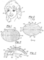
- Figure 1 is a perspective view illustrating a preferred embodiment of the present invention in use;
- Figure 2 is a front view illustrating the preferred embodiment of the invention;
- Figure 3 is a cross-sectional view taken substantially along line 3-3 in Figure 2; and
- Figure 4 is a view similar to Figure 2 but showing a modification thereof.
- With reference first to Figure 1, a preferred embodiment of the eye protector of the present invention is thereshown and comprises a pair of
eye protectors 10 adapted to be positioned over the eyes of asunbather 12. Theeye protectors 10 for both the right and left eyes are substantially mirror images to each other. - With reference now to FIGS. 2 and 3, the
eye protector 10 is thereshown in greater detail and comprises abody 14 having anupper edge 16,side edges 18, and alower edge 22. As best shown in FIG. 3, anarcuate section 24 having a concaveposterior surface 26 and a convexanterior surface 28 extends continuously between theupper edge 16 andlower edge 22. Furthermore, thebody 14 is dimensioned so that, with the body positioned over an eye as shown in FIGS. 1 and 3, theupper edge 16 abuts the sunbather's face closely adjacent to but above the eye 21 (FIG. 3) while, conversely, thelower edge 22 abuts against the sunbather's face below but closely adjacent theeye 21. In doing so, the concaveposterior surface 26 of thearcuate section 24 is spaced outwardly from the user'seye 21. - With reference now particularly to FIG. 3, the thickness of the
body 14 decreases substantially continually from theupper edge 16 and to thelower edge 22. Consequently, the weight of theupper half 30 of thebody 14, i.e. the portion of thebody 14 between atransverse midline 32 and theupper edge 16, is greater in weight than thelower half 34 of thebody 14. In practice, it has been found that the heavier weight in theupper half 30 of thebody 14 renders theeye protector 10 less susceptible to dislodgement despite relatively rapid movement of the sunbather's head. This occurs since theupper edge 16 of thebody 14 nests within the natural cavity 36 (FIG. 3) formed between the sunbather'seyebrow 38 andupper eyelid 40. - Although in the preferred embodiment of the invention the thickness of the
upper half 30 of thebody 14 is greater than thelower half 34 to thereby increase the weight of theupper half 30, other means can be alternatively used to increase the weight of theupper half 30 of thebody 14. For example, thebody 14 can include weights (not shown) in itsupper half 30 while maintaining a substantially constant body thickness between itsupper edge 16 andlower edge 22. - With reference now to FIGS. 2 and 3, a plurality of
spaced ridges 44 protrude outwardly from theanterior surface 28 of thebody 14. Theseridges 44 preferably extend transversely across thebody 14 and form cooling fins to dissipate heat from theeye protector body 14. In practice, thesecooling fins 44 have been found to keep theeye protector 10 relatively cool thereby maintaining the sunbather's eye in a cool and comfortable state. Theanterior surface 28 is also preferably of a reflective color to minimize the heating of theeye protector 10 by radiant energy. - Although the
ridges 44 preferably extend transversely or laterally across thebody 14, as shown in FIG. 4, theridges 44 can alternatively extend vertically, as shown at 100, or both vertically and laterally, as shown at 102. Furthermore, as shown in FIG. 4, any combination of vertical and/or lateral ridges can be used. Referring now particularly to Figures 2 and 3, ventilation openings (60, 62) are provided in the opposite lateral sides (18) of the body (14). These ventilation openings (60, 62) allow air circulation and air cooling of the user's eyes (40) while still protecting the eyes from solar radiation. - From the foregoing, it can be seen that the eye protector (10) of the present invention provides a simple and yet highly effective means for protecting a sunbather's eyes from radiant energy from the sun, sun lamps or the like.
- It will be appreciated from Figure 3 that the lateral curvature of the arcuate portion is non-uniform, having a shorter radius of curvature on one side of the longitudinal (or transverse) mid-line (32) than on the other. Non-uniformity of the curvature may also contribute to the differential weight distribution above and below the horizontal mid-line.
Claims (6)
- An eye protector comprising: a body (14) having an upper edge (16), a lower edge (22) and an arcuate section (24) extending between said upper and lower edges, said body (14) being dimensioned so that, with said body positioned over a human eye, said upper edge is positioned closely adjacent and above the eye, said lower edge is positioned closely adjacent and below the eye and said arcuate section is spaced outwardly from and covers the eye, the said body (14) being formed such that the weight of said body between a transverse midline (32) on said arcuate section and the said upper edge (16) is greater than the weight of said body between said midline (32) and the said lower edge (22), characterised in that the said body (14) is provided with an air ventilation opening (60,62) on at least one side of the body (14).
- An eye protector according to Claim 1, characterized in that the said arcuate portion (24) has a thickness which decreases from the upper edge (16) to the lower edge (22).
- An eye protector as claimed in Claim 2, characterized in that the thickness of the arcuate portion (24) of the body decreases substantially continuously from the upper edge (16) to the lower edge (22).
- An eye protector according to Claim 1, Claim 2 or Claim 3, characterized in that the said arcuate portion (24) has a posterior surface (26) adapted to face the eye (21) and an anterior surface (28) adapted to face away from the eye, and has a plurality of spaced ridges (44) which protrude outwardly from the anterior surface.
- An eye protector according to Claim 4, characterized in that at least some of the said ridges (44) extend transversely across the said anterior surface.
- An eye protector according to Claim 4 or Claim 5, characterized in that at least some of the said ridges (44) extend vertically (100) across said anterior surface.
Applications Claiming Priority (2)
| Application Number | Priority Date | Filing Date | Title |
|---|---|---|---|
| US353058 | 1989-05-17 | ||
| US07/353,058 US5263200A (en) | 1989-05-17 | 1989-05-17 | Eye protector |
Publications (2)
| Publication Number | Publication Date |
|---|---|
| EP0403083A1 EP0403083A1 (en) | 1990-12-19 |
| EP0403083B1 true EP0403083B1 (en) | 1996-08-21 |
Family
ID=23387603
Family Applications (1)
| Application Number | Title | Priority Date | Filing Date |
|---|---|---|---|
| EP90305398A Expired - Lifetime EP0403083B1 (en) | 1989-05-17 | 1990-05-17 | Eye protector |
Country Status (4)
| Country | Link |
|---|---|
| US (1) | US5263200A (en) |
| EP (1) | EP0403083B1 (en) |
| AT (1) | ATE141490T1 (en) |
| DE (1) | DE69028155D1 (en) |
Families Citing this family (11)
| Publication number | Priority date | Publication date | Assignee | Title |
|---|---|---|---|---|
| US5782672A (en) * | 1996-05-28 | 1998-07-21 | Woodley; Vickie G. | Nipple pad |
| USD425623S (en) * | 1999-04-08 | 2000-05-23 | Funk Donald E | Attachable eye protector |
| US20080086792A1 (en) | 2006-10-13 | 2008-04-17 | Thomas Charles Kuracina | Method and apparatus for diverting sweat, liquid, moisture or the like from an eye |
| US7052130B2 (en) * | 2003-12-30 | 2006-05-30 | Ep Acquisition, Inc. | Protective eyewear |
| WO2008082770A1 (en) * | 2006-12-28 | 2008-07-10 | Hogan Christine K | Protective eyewear |
| US8556413B2 (en) | 2010-12-03 | 2013-10-15 | Christine K Hogan | Protective eyewear |
| US8967427B2 (en) | 2012-09-07 | 2015-03-03 | Christine K. Hogan | Portable eye protection system and method |
| WO2020072468A1 (en) | 2018-10-01 | 2020-04-09 | Biovisics Medical, Llc | System and methods for controlled electrical modulation for vision therapy |
| US11305118B2 (en) | 2018-11-30 | 2022-04-19 | Biovisics Medical, Inc. | Head worn apparatuses for vision therapy |
| EP3952979A1 (en) | 2019-04-10 | 2022-02-16 | Biovisics Medical, Inc. | Systems and interfaces for ocular therapy |
| US11511112B2 (en) | 2019-06-14 | 2022-11-29 | Biovisics Medical, Inc. | Wearable medical device |
Citations (1)
| Publication number | Priority date | Publication date | Assignee | Title |
|---|---|---|---|---|
| US4642816A (en) * | 1986-01-13 | 1987-02-17 | Anne Miller | Eye protector |
Family Cites Families (19)
| Publication number | Priority date | Publication date | Assignee | Title |
|---|---|---|---|---|
| US2165668A (en) * | 1938-04-04 | 1939-07-11 | Harry Jacobson | Eye protector |
| US2283752A (en) * | 1940-05-10 | 1942-05-19 | Faust R Gonsett | Eye shield |
| US2537275A (en) * | 1945-04-09 | 1951-01-09 | Chicago Eye Shield Company | Nonfogging goggle |
| US2527947A (en) * | 1947-12-22 | 1950-10-31 | Loos Marie | Eye protector |
| US2715223A (en) * | 1952-04-24 | 1955-08-16 | Bausch & Lomb | Goggles |
| US3020552A (en) * | 1959-11-30 | 1962-02-13 | Audrey M Coon | Sunbathing glasses |
| US3012248A (en) * | 1960-05-31 | 1961-12-12 | Kleinman Maurice | Anti-fog lens |
| US3258879A (en) * | 1963-11-04 | 1966-07-05 | Carlyle A Edelstein | Apparatus for grinding contact lenses |
| US3619815A (en) * | 1969-10-31 | 1971-11-16 | Daniel D Towner Jr | Eyelid shield |
| US4055378A (en) * | 1971-12-31 | 1977-10-25 | Agfa-Gevaert Aktiengesellschaft | Silicone contact lens with hydrophilic surface treatment |
| US4024405A (en) * | 1975-12-04 | 1977-05-17 | Szot Frank A | X-ray eye shield |
| US4162542A (en) * | 1977-05-09 | 1979-07-31 | Frank Jerome M | Eye protectors |
| US4211476A (en) * | 1978-12-29 | 1980-07-08 | Allan J. Brummel | Contact lenses with angular orientation and stabilization |
| FR2483631A1 (en) * | 1980-05-30 | 1981-12-04 | Giroldi Giovanni | Shading of sunglasses lenses - with respect to notch to give accurate location of shading |
| US4411263A (en) * | 1981-09-23 | 1983-10-25 | Gayle Cook | Infant eye shield |
| US4502476A (en) * | 1982-08-18 | 1985-03-05 | Claire Doolin Welt | Protective eye cover |
| US4621912A (en) * | 1985-02-14 | 1986-11-11 | Meyer Donald R | Foraminated optical contact lens |
| US4701962A (en) * | 1985-12-24 | 1987-10-27 | Eye Pro, Inc. | Protective eyewear |
| US4810082A (en) * | 1987-07-01 | 1989-03-07 | Abel Robert Jr | Corneal onlay lens |
-
1989
- 1989-05-17 US US07/353,058 patent/US5263200A/en not_active Expired - Fee Related
-
1990
- 1990-05-17 EP EP90305398A patent/EP0403083B1/en not_active Expired - Lifetime
- 1990-05-17 DE DE69028155T patent/DE69028155D1/en not_active Expired - Lifetime
- 1990-05-17 AT AT90305398T patent/ATE141490T1/en active
Patent Citations (1)
| Publication number | Priority date | Publication date | Assignee | Title |
|---|---|---|---|---|
| US4642816A (en) * | 1986-01-13 | 1987-02-17 | Anne Miller | Eye protector |
Also Published As
| Publication number | Publication date |
|---|---|
| DE69028155D1 (en) | 1996-09-26 |
| ATE141490T1 (en) | 1996-09-15 |
| EP0403083A1 (en) | 1990-12-19 |
| US5263200A (en) | 1993-11-23 |
Similar Documents
| Publication | Publication Date | Title |
|---|---|---|
| CA1118246A (en) | Sports spectacle structure | |
| US4162542A (en) | Eye protectors | |
| CA1178753A (en) | Safety goggle | |
| EP0403083B1 (en) | Eye protector | |
| CA1311587C (en) | Protective surgical face mask | |
| US4877320A (en) | Eye-shielding glasses | |
| US4662729A (en) | Clip-on cuffs for eyeglass temples | |
| US5012527A (en) | Athletic nose guard | |
| US5666664A (en) | Face protector shade | |
| US2563125A (en) | Safety goggles | |
| US6481845B1 (en) | Eyewear with detachable lens portion | |
| US6305389B1 (en) | Mascara application guard | |
| US6065833A (en) | Sporting eyeglasses | |
| US5533208A (en) | Folding adjustable glasses on cap peak | |
| US5857218A (en) | Protective visor for hair treatment | |
| EP0223371A1 (en) | Spectacles, visors and the like | |
| US6029271A (en) | Facial sun block mask | |
| US20160338429A1 (en) | Protective skin shields system | |
| US4642816A (en) | Eye protector | |
| EP0346480B1 (en) | Wig having shape retaining member | |
| US5717992A (en) | Nose guard | |
| US5243711A (en) | Protective eye shield | |
| US2368303A (en) | Protective goggle | |
| US4656668A (en) | Eye protector | |
| US5413119A (en) | Protective eye shield for dental patients |
Legal Events
| Date | Code | Title | Description |
|---|---|---|---|
| PUAI | Public reference made under article 153(3) epc to a published international application that has entered the european phase |
Free format text: ORIGINAL CODE: 0009012 |
|
| AK | Designated contracting states |
Kind code of ref document: A1 Designated state(s): AT BE CH DE DK ES FR GB GR IT LI LU NL SE |
|
| 17P | Request for examination filed |
Effective date: 19910619 |
|
| 17Q | First examination report despatched |
Effective date: 19921116 |
|
| GRAA | (expected) grant |
Free format text: ORIGINAL CODE: 0009210 |
|
| GRAH | Despatch of communication of intention to grant a patent |
Free format text: ORIGINAL CODE: EPIDOS IGRA |
|
| AK | Designated contracting states |
Kind code of ref document: B1 Designated state(s): AT BE CH DE DK ES FR GB GR IT LI LU NL SE |
|
| PG25 | Lapsed in a contracting state [announced via postgrant information from national office to epo] |
Ref country code: LI Effective date: 19960821 Ref country code: CH Effective date: 19960821 Ref country code: BE Effective date: 19960821 Ref country code: IT Free format text: LAPSE BECAUSE OF FAILURE TO SUBMIT A TRANSLATION OF THE DESCRIPTION OR TO PAY THE FEE WITHIN THE PRESCRIBED TIME-LIMIT;WARNING: LAPSES OF ITALIAN PATENTS WITH EFFECTIVE DATE BEFORE 2007 MAY HAVE OCCURRED AT ANY TIME BEFORE 2007. THE CORRECT EFFECTIVE DATE MAY BE DIFFERENT FROM THE ONE RECORDED. Effective date: 19960821 Ref country code: ES Free format text: THE PATENT HAS BEEN ANNULLED BY A DECISION OF A NATIONAL AUTHORITY Effective date: 19960821 Ref country code: NL Free format text: LAPSE BECAUSE OF FAILURE TO SUBMIT A TRANSLATION OF THE DESCRIPTION OR TO PAY THE FEE WITHIN THE PRESCRIBED TIME-LIMIT Effective date: 19960821 Ref country code: AT Effective date: 19960821 Ref country code: GR Free format text: LAPSE BECAUSE OF FAILURE TO SUBMIT A TRANSLATION OF THE DESCRIPTION OR TO PAY THE FEE WITHIN THE PRESCRIBED TIME-LIMIT Effective date: 19960821 Ref country code: FR Effective date: 19960821 Ref country code: DK Effective date: 19960821 |
|
| REF | Corresponds to: |
Ref document number: 141490 Country of ref document: AT Date of ref document: 19960915 Kind code of ref document: T |
|
| REF | Corresponds to: |
Ref document number: 69028155 Country of ref document: DE Date of ref document: 19960926 |
|
| PG25 | Lapsed in a contracting state [announced via postgrant information from national office to epo] |
Ref country code: SE Effective date: 19961121 |
|
| PG25 | Lapsed in a contracting state [announced via postgrant information from national office to epo] |
Ref country code: DE Effective date: 19961122 |
|
| EN | Fr: translation not filed | ||
| NLV1 | Nl: lapsed or annulled due to failure to fulfill the requirements of art. 29p and 29m of the patents act | ||
| REG | Reference to a national code |
Ref country code: CH Ref legal event code: PL |
|
| PG25 | Lapsed in a contracting state [announced via postgrant information from national office to epo] |
Ref country code: GB Effective date: 19970517 |
|
| PG25 | Lapsed in a contracting state [announced via postgrant information from national office to epo] |
Ref country code: LU Free format text: LAPSE BECAUSE OF NON-PAYMENT OF DUE FEES Effective date: 19970531 |
|
| PLBE | No opposition filed within time limit |
Free format text: ORIGINAL CODE: 0009261 |
|
| STAA | Information on the status of an ep patent application or granted ep patent |
Free format text: STATUS: NO OPPOSITION FILED WITHIN TIME LIMIT |
|
| 26N | No opposition filed | ||
| GBPC | Gb: european patent ceased through non-payment of renewal fee |
Effective date: 19970517 |