EP0403052B1 - Nickel electrode and alkaline battery using the same - Google Patents
Nickel electrode and alkaline battery using the same Download PDFInfo
- Publication number
- EP0403052B1 EP0403052B1 EP90303732A EP90303732A EP0403052B1 EP 0403052 B1 EP0403052 B1 EP 0403052B1 EP 90303732 A EP90303732 A EP 90303732A EP 90303732 A EP90303732 A EP 90303732A EP 0403052 B1 EP0403052 B1 EP 0403052B1
- Authority
- EP
- European Patent Office
- Prior art keywords
- current collector
- active material
- nickel
- electrode
- cobalt
- Prior art date
- Legal status (The legal status is an assumption and is not a legal conclusion. Google has not performed a legal analysis and makes no representation as to the accuracy of the status listed.)
- Expired - Lifetime
Links
- PXHVJJICTQNCMI-UHFFFAOYSA-N Nickel Chemical compound [Ni] PXHVJJICTQNCMI-UHFFFAOYSA-N 0.000 title claims description 78
- 229910052759 nickel Inorganic materials 0.000 title description 33
- 239000011149 active material Substances 0.000 claims description 59
- 238000000034 method Methods 0.000 claims description 34
- 239000004020 conductor Substances 0.000 claims description 28
- 239000000843 powder Substances 0.000 claims description 21
- 150000001869 cobalt compounds Chemical class 0.000 claims description 16
- 239000002184 metal Substances 0.000 claims description 16
- 229910052751 metal Inorganic materials 0.000 claims description 16
- BFDHFSHZJLFAMC-UHFFFAOYSA-L nickel(ii) hydroxide Chemical compound [OH-].[OH-].[Ni+2] BFDHFSHZJLFAMC-UHFFFAOYSA-L 0.000 claims description 15
- -1 cobalt oxyhydroxide Chemical compound 0.000 claims description 13
- 239000000463 material Substances 0.000 claims description 11
- OKTJSMMVPCPJKN-UHFFFAOYSA-N Carbon Chemical compound [C] OKTJSMMVPCPJKN-UHFFFAOYSA-N 0.000 claims description 9
- 229910021503 Cobalt(II) hydroxide Inorganic materials 0.000 claims description 9
- 238000006722 reduction reaction Methods 0.000 claims description 8
- 229910052799 carbon Inorganic materials 0.000 claims description 6
- 239000002482 conductive additive Substances 0.000 claims description 5
- 238000003825 pressing Methods 0.000 claims description 5
- 239000003792 electrolyte Substances 0.000 claims description 4
- 230000003647 oxidation Effects 0.000 claims description 4
- 238000007254 oxidation reaction Methods 0.000 claims description 4
- ASKVAEGIVYSGNY-UHFFFAOYSA-L cobalt(ii) hydroxide Chemical compound [OH-].[OH-].[Co+2] ASKVAEGIVYSGNY-UHFFFAOYSA-L 0.000 claims description 3
- 238000001035 drying Methods 0.000 claims description 3
- IVMYJDGYRUAWML-UHFFFAOYSA-N cobalt(II) oxide Inorganic materials [Co]=O IVMYJDGYRUAWML-UHFFFAOYSA-N 0.000 description 23
- 239000000203 mixture Substances 0.000 description 7
- 229910017052 cobalt Inorganic materials 0.000 description 6
- 239000010941 cobalt Substances 0.000 description 6
- GUTLYIVDDKVIGB-UHFFFAOYSA-N cobalt atom Chemical compound [Co] GUTLYIVDDKVIGB-UHFFFAOYSA-N 0.000 description 6
- 230000000694 effects Effects 0.000 description 6
- 239000000835 fiber Substances 0.000 description 6
- 238000004519 manufacturing process Methods 0.000 description 5
- 238000007747 plating Methods 0.000 description 5
- 239000002002 slurry Substances 0.000 description 5
- 238000007599 discharging Methods 0.000 description 4
- 239000002245 particle Substances 0.000 description 4
- 239000000243 solution Substances 0.000 description 4
- 239000012670 alkaline solution Substances 0.000 description 3
- 230000015572 biosynthetic process Effects 0.000 description 3
- 229910052793 cadmium Inorganic materials 0.000 description 3
- BDOSMKKIYDKNTQ-UHFFFAOYSA-N cadmium atom Chemical compound [Cd] BDOSMKKIYDKNTQ-UHFFFAOYSA-N 0.000 description 3
- 238000006243 chemical reaction Methods 0.000 description 3
- 239000011248 coating agent Substances 0.000 description 3
- 238000000576 coating method Methods 0.000 description 3
- 238000005260 corrosion Methods 0.000 description 3
- 230000007797 corrosion Effects 0.000 description 3
- 238000003411 electrode reaction Methods 0.000 description 3
- 229910006279 γ-NiOOH Inorganic materials 0.000 description 3
- 229920002134 Carboxymethyl cellulose Polymers 0.000 description 2
- 239000000654 additive Substances 0.000 description 2
- 239000007864 aqueous solution Substances 0.000 description 2
- 239000001768 carboxy methyl cellulose Substances 0.000 description 2
- 235000010948 carboxy methyl cellulose Nutrition 0.000 description 2
- 239000008112 carboxymethyl-cellulose Substances 0.000 description 2
- 230000002860 competitive effect Effects 0.000 description 2
- 239000004744 fabric Substances 0.000 description 2
- 238000011068 loading method Methods 0.000 description 2
- 229910000000 metal hydroxide Inorganic materials 0.000 description 2
- 150000004692 metal hydroxides Chemical class 0.000 description 2
- 150000002815 nickel Chemical class 0.000 description 2
- 238000005245 sintering Methods 0.000 description 2
- 239000000758 substrate Substances 0.000 description 2
- 230000002195 synergetic effect Effects 0.000 description 2
- UGFAIRIUMAVXCW-UHFFFAOYSA-N Carbon monoxide Chemical compound [O+]#[C-] UGFAIRIUMAVXCW-UHFFFAOYSA-N 0.000 description 1
- 229910000831 Steel Inorganic materials 0.000 description 1
- 239000000956 alloy Substances 0.000 description 1
- 229910002064 alloy oxide Inorganic materials 0.000 description 1
- 239000011230 binding agent Substances 0.000 description 1
- OJIJEKBXJYRIBZ-UHFFFAOYSA-N cadmium nickel Chemical compound [Ni].[Cd] OJIJEKBXJYRIBZ-UHFFFAOYSA-N 0.000 description 1
- MPMSMUBQXQALQI-UHFFFAOYSA-N cobalt phthalocyanine Chemical compound [Co+2].C12=CC=CC=C2C(N=C2[N-]C(C3=CC=CC=C32)=N2)=NC1=NC([C]1C=CC=CC1=1)=NC=1N=C1[C]3C=CC=CC3=C2[N-]1 MPMSMUBQXQALQI-UHFFFAOYSA-N 0.000 description 1
- 229940125898 compound 5 Drugs 0.000 description 1
- 238000007796 conventional method Methods 0.000 description 1
- 230000010485 coping Effects 0.000 description 1
- 238000002474 experimental method Methods 0.000 description 1
- 239000011888 foil Substances 0.000 description 1
- 238000010438 heat treatment Methods 0.000 description 1
- 239000012510 hollow fiber Substances 0.000 description 1
- 238000005470 impregnation Methods 0.000 description 1
- 150000002500 ions Chemical class 0.000 description 1
- 229910044991 metal oxide Inorganic materials 0.000 description 1
- 150000004706 metal oxides Chemical class 0.000 description 1
- 239000002923 metal particle Substances 0.000 description 1
- 229920001343 polytetrafluoroethylene Polymers 0.000 description 1
- 239000004810 polytetrafluoroethylene Substances 0.000 description 1
- 239000011148 porous material Substances 0.000 description 1
- 230000036647 reaction Effects 0.000 description 1
- 238000002791 soaking Methods 0.000 description 1
- 239000010959 steel Substances 0.000 description 1
- XLYOFNOQVPJJNP-UHFFFAOYSA-N water Substances O XLYOFNOQVPJJNP-UHFFFAOYSA-N 0.000 description 1
Images




Classifications
-
- H—ELECTRICITY
- H01—ELECTRIC ELEMENTS
- H01M—PROCESSES OR MEANS, e.g. BATTERIES, FOR THE DIRECT CONVERSION OF CHEMICAL ENERGY INTO ELECTRICAL ENERGY
- H01M4/00—Electrodes
- H01M4/02—Electrodes composed of, or comprising, active material
- H01M4/24—Electrodes for alkaline accumulators
- H01M4/32—Nickel oxide or hydroxide electrodes
-
- H—ELECTRICITY
- H01—ELECTRIC ELEMENTS
- H01M—PROCESSES OR MEANS, e.g. BATTERIES, FOR THE DIRECT CONVERSION OF CHEMICAL ENERGY INTO ELECTRICAL ENERGY
- H01M10/00—Secondary cells; Manufacture thereof
- H01M10/24—Alkaline accumulators
- H01M10/30—Nickel accumulators
-
- H—ELECTRICITY
- H01—ELECTRIC ELEMENTS
- H01M—PROCESSES OR MEANS, e.g. BATTERIES, FOR THE DIRECT CONVERSION OF CHEMICAL ENERGY INTO ELECTRICAL ENERGY
- H01M4/00—Electrodes
- H01M4/02—Electrodes composed of, or comprising, active material
- H01M4/36—Selection of substances as active materials, active masses, active liquids
- H01M4/48—Selection of substances as active materials, active masses, active liquids of inorganic oxides or hydroxides
- H01M4/52—Selection of substances as active materials, active masses, active liquids of inorganic oxides or hydroxides of nickel, cobalt or iron
-
- H—ELECTRICITY
- H01—ELECTRIC ELEMENTS
- H01M—PROCESSES OR MEANS, e.g. BATTERIES, FOR THE DIRECT CONVERSION OF CHEMICAL ENERGY INTO ELECTRICAL ENERGY
- H01M4/00—Electrodes
- H01M4/02—Electrodes composed of, or comprising, active material
- H01M4/62—Selection of inactive substances as ingredients for active masses, e.g. binders, fillers
- H01M4/624—Electric conductive fillers
-
- H—ELECTRICITY
- H01—ELECTRIC ELEMENTS
- H01M—PROCESSES OR MEANS, e.g. BATTERIES, FOR THE DIRECT CONVERSION OF CHEMICAL ENERGY INTO ELECTRICAL ENERGY
- H01M4/00—Electrodes
- H01M4/02—Electrodes composed of, or comprising, active material
- H01M4/64—Carriers or collectors
- H01M4/66—Selection of materials
- H01M4/661—Metal or alloys, e.g. alloy coatings
-
- H—ELECTRICITY
- H01—ELECTRIC ELEMENTS
- H01M—PROCESSES OR MEANS, e.g. BATTERIES, FOR THE DIRECT CONVERSION OF CHEMICAL ENERGY INTO ELECTRICAL ENERGY
- H01M4/00—Electrodes
- H01M4/02—Electrodes composed of, or comprising, active material
- H01M4/62—Selection of inactive substances as ingredients for active masses, e.g. binders, fillers
- H01M4/624—Electric conductive fillers
- H01M4/625—Carbon or graphite
-
- Y—GENERAL TAGGING OF NEW TECHNOLOGICAL DEVELOPMENTS; GENERAL TAGGING OF CROSS-SECTIONAL TECHNOLOGIES SPANNING OVER SEVERAL SECTIONS OF THE IPC; TECHNICAL SUBJECTS COVERED BY FORMER USPC CROSS-REFERENCE ART COLLECTIONS [XRACs] AND DIGESTS
- Y02—TECHNOLOGIES OR APPLICATIONS FOR MITIGATION OR ADAPTATION AGAINST CLIMATE CHANGE
- Y02E—REDUCTION OF GREENHOUSE GAS [GHG] EMISSIONS, RELATED TO ENERGY GENERATION, TRANSMISSION OR DISTRIBUTION
- Y02E60/00—Enabling technologies; Technologies with a potential or indirect contribution to GHG emissions mitigation
- Y02E60/10—Energy storage using batteries
-
- Y—GENERAL TAGGING OF NEW TECHNOLOGICAL DEVELOPMENTS; GENERAL TAGGING OF CROSS-SECTIONAL TECHNOLOGIES SPANNING OVER SEVERAL SECTIONS OF THE IPC; TECHNICAL SUBJECTS COVERED BY FORMER USPC CROSS-REFERENCE ART COLLECTIONS [XRACs] AND DIGESTS
- Y02—TECHNOLOGIES OR APPLICATIONS FOR MITIGATION OR ADAPTATION AGAINST CLIMATE CHANGE
- Y02P—CLIMATE CHANGE MITIGATION TECHNOLOGIES IN THE PRODUCTION OR PROCESSING OF GOODS
- Y02P70/00—Climate change mitigation technologies in the production process for final industrial or consumer products
- Y02P70/50—Manufacturing or production processes characterised by the final manufactured product
Definitions
- the present invention concerns a nickel electrode for use in an alkaline battery and an alkaline battery using such a nickel electrode.
- Production process for a nickel electrode for use in a nickel-cadmium battery known at present includes the following two methods, i.e., a so-called sintering method of inpregnating a finely porous substrate (80% porosity) prepared by sintering nickel powder to a perforated steel sheet with a nickel salt under a reduced pressure and then converting the nickel salt into nickel hydroxide in an aqueous alkaline solution, and a so-called pasting method of loading nickel hydroxide powder in a slurry form to a highly porous current collector (90 ⁇ 98% porosity) made of sintered alkaline-proof metal fibers.
- a so-called sintering method of inpregnating a finely porous substrate (80% porosity) prepared by sintering nickel powder to a perforated steel sheet with a nickel salt under a reduced pressure and then converting the nickel salt into nickel hydroxide in an aqueous alkaline solution and a so-called pasting method of loading nickel hydro
- the former method was developed during the World War II, which has been improved for every particular portion upto now.
- no principal changes have been made and it requires to repeat, over several cycles, a series of complicate loading steps, that is, solution impregnation alkaline soaking, water rinsing and drying. Accordingly, it has a drawback of being expensive.
- the energy density is linited to about 400 mAh/cc due to the structural factor, it has become difficult to satisfy the market needs along with the reduction for the weight and size of portable electronic equipment which has been under rapid progress at present (requiring about 600 mAh/cc).
- the pasting method has been developed in recent years for simplifying the production steps from wide point of views such as for current collectors, active materials and additives.
- Such hollow fiber material has already been used in FR-A-2512075, but no pressing step was applied.
- this material hereinafter simply referred to as a mesh current collector
- the utilization ratio of the active material hereinafter simply referred to as the utilization ratio
- the electrode is generally comprised of three portions, that is, a current collector portion, a boundary portion between the current collector and the first layer of the active material layer adjacent therewith (hereinafter simply referred to as a boundary portion), and an active material layer portion. Then, the study was made for each of the portions of the electrode individually.
- the conductivity of the current collector portion is sufficient with the present structure and there is no problem to be solved. Accordingly, a study as to the effect of the conductivity of the boundary portion on the utilization ratio was carried out at first.
- the oxyhydroxide layer formed at the surface of the current collector by this method can also obtain a further effect of improving the corrosion resistance of the current collector, thereby extending the working life of the electrode.
- the improvement of the conductivity of the active material layer can be attained by adding powder of conductive material, such as carbon and nickel, or powder of a divalent cobalt compound, such as cobalt monoxide and cobalt hydroxide (refer to Japanese Patent Laid Open Sho 62-256366), to the active material.
- the aim of the former method is improvement of the conductivity of the active material layer by addition of the highly conductive material but it involves a problem in view of the energy density since it is necessary to add an extremely great amount of the conductive material. Further, since it is necessary to press the electrode on both sides at a high pressure, there is a problem in view of the production.
- the latter method also aims at improvement of the conductivity of the active material layer by the formation of conductive network of the cobalt oxyhydroxide in the said layer.
- the divalent cobalt compound added to the active material is once converted into blue complex ions in an alkaline solution at high concentration and re-deposited on the surface of the active material, which are converted into cobalt oxyhydroxide possessing conductivity by the first charge.
- This method is effective in using the sintered highly porous fiber current collector in which the distance between the active material and the current collector is relatively short. However, it is not sufficient for the mesh current collector in which this distance is greater than the effective distance of the conductive network. When such a conventional method has been applied actually to the mesh current collector, only an extremely low utilization ratio of the active material can be obtained. Accordingly, for improving the conductivity of the active material layer in using the mesh current collector, merely the addition method as in the prior art is still insufficient and it is necessary for a further consideration on the additives.
- the discharge of the active material occurs from the vicinity of the current collector.
- the thickness of actually actuated active material layer can be calculated by a mathematical product of the thickness of the active material layer and its utilization ratio.
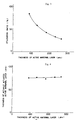
- Fig. 4 is obtained by applying the mathematical process to Fig. 3. It can be seen from Fig.5 that the thickness of the actuated active material layer has a substantially constant value even if that of the pasted active material layer is varied. Therefore it is estimated that the effective distance of the conductive network formed in this case is about 70 to 80 »m.
- the divalent cobalt compound 5 added to the active material 7 with the conductive material 6 is dissolved and re-deposited on the surface of the conductive material, the active material and the current collector 4, the divalent cobalt compound being converted into cobalt oxyhydroxide 9 by the first charge.
- Fig. 5(a) ⁇ (c) show a model of forming the conductive network.
- the conductive material 6 has to be alkaline-proof and causing no or less change due to the electrode reactions. That is, alkaline-proof metal, alloy or metal oxide, conductive material coated with alkaline-proof metal or carbon are appropriate.
- This addition method has proved to improve the utilization ratio. Further, it has become apparent that the conductive material has an effect of improving the conductivity of the active material in a smaller addition amount as compared with the case where the conductive material is added alone.
- this conductive network is formed by connecting each particle of the conductive material by cobalt oxyhydroxide, a network connecting "line” is more effective than a network connecting "point” as powder. Thus a fibrous shape is more effective for the conductive material.
- too long fibers may cause an heterogenous state in the active material layer, its length is desirably within such a range as not causing heterogenity.
- an object of the present invention to provide an inexpensive nickel electrode of high performance, great capacity and high productivity, as well as an alkaline battery using such a nickel electrode.
- the present invention provides a method of constructing an alkaline battery, comprising:
- the active material comprises nickel hydroxide powder added divalent cobalt compound powder in combination with conductive material powder.
- the divalent cobalt compound is at least one or more of CoO, ⁇ - Co(OH)2 and ⁇ - Co(OH)2.
- the conductive additives are selected from a metal stable in an oxidation/reduction reaction, a conductive material coated with a metal stable in an oxidation/reduction reaction and carbon.
- the conductive additive is short fibrous.
- An aqueous solution comprising carboxymethyl cellulose as a viscosity inprover was respectively added to a mixture of 80% by weight of the nickel hydroxide powder and 20% by weight of the cobalt monoxide powder (hereinafter simply referred to as A); a mixture of 80% by weight of the nickel hydroxide powder and 20% by weight of the carbon powder (hereinafter simply referred to as B); and a mixture of 80% by weight of the nickel hydroxide powder, 10% by weight of the cobalt monoxide powder and 10% by weight of the carbon powder (hereinafter simply referred to as C), to form three kinds of slurry active materials.
- A a mixture of 80% by weight of the nickel hydroxide powder and 20% by weight of the cobalt monoxide powder
- B a mixture of 80% by weight of the nickel hydroxide powder, 10% by weight of the cobalt monoxide powder and 10% by weight of the carbon powder
- C a mixture of 80% by weight of the nickel hydroxide powder, 10% by weight of the co
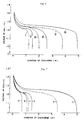
- Fig. 6 shows cell discharge characteristics in respective cases.
- conditions for the nickel electrodes I ⁇ VI are shown in the following Table 1.
- An aqueous solution comprising carboxymethyl cellulose as a viscosity improver was respectively added to a mixture of 60% by weight of the nickel hydroxide powder and 40% by weight of the cobalt monoxide powder (hereinafter simply referred to as D); a mixture of 60% by weight of the nickel hydroxide powder and 40% by weight of the nickel powder (hereinafter simply referred to as E); and a mixture of 80% by weight of the nickel hydroxide powder, 10% by weight of the cobalt monoxide powder and 30% by weight of the nickel powder (hereinafter simply referred to as F), to form another three kinds of slurry active materials.
- D 60% by weight of the nickel hydroxide powder and 40% by weight of the cobalt monoxide powder
- E a mixture of 60% by weight of the nickel hydroxide powder and 40% by weight of the nickel powder
- F a mixture of 80% by weight of the nickel hydroxide powder, 10% by weight of the cobalt monoxide powder and 30% by weight of the nickel powder
- Fig. 7 shows cell discharge characteristics in respective cases.
- conditions for the nickel electrodes a ⁇ f are shown in the following Table 2.
- the active material sheet was press-bonded to a nickel mesh current collector at 80 um wire diameter applied with plating of cobalt 3 um thickness, which was dried and pressed into a nickel electrodes of 600 um (0.6mm) thickness.
- Fig. 8 shows cell discharge characteristics for Example 3.
- the method of adding cobalt monoxide alone to nickel hydroxide in Example 1 and 2 was used in the sintered metal fibre current collector, in which substantially 100% utilization ratio could be obtained. However, only about 25% to 30% of the utilization ratio could be obtained for the mesh current collector. Further, in the method of adding a carbon or nickel powder alone to nickel hydroxide, only about 80% utilization ratio could be obtained although a great amount was added even in a case of existent pocket-type and button-type nickel electrodes in which a greater amount was added than in the present invention. Moreover, the utilization ratio could be obtained only for about 40 to 50% in the case of carbon and 18 to 20% in the case of nickel for the mesh current collector. In the present invention's method of adding cobalt monoxide and the conductive material in combination, about 100% of utilization ratio could be obtained in both of the examples. Thus this method is extremely effective for the mesh current collector.
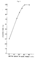
- the thickness of the active material layer from the current collector is about 300 »m. Since the effective distance of the conductive network of cobalt oxyhydroxide alone is considered to be about 70 to 80 »m, about 230 to 240 »m excepting the above-mentioned distance is compensated by the conductive material. In order to investigate a relationship between the effective distance compensated by the conductive material and the addition amount of the conductive material, the model experiment was made by changing the addition amount of the nickel powder variously. Fig. 9 shows the results. It can be seen from the figure that the utilization ratio is increased along with the increase in the addition amount of the nickel powder.
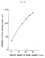
- Fig. 10 shows this relationship. It can be seen from the figure that an optimum addition amount is present depending on the thickness of the active material layer. For the shape and the size of the conductive material, an optimum condition is also considered to be present. For the shape, a short fibrous form is effective due to the synergistic effect and they function extremely effective, in particular, in the high rate discharging as compared with the powdered form. Accordingly, it is apparent that the boundary portion plays an important role for the utilization ratio.
- Fig. 11 shows a model, in the cross section, of the nickel electrode using the mesh current collector with the boundary portion comprising the cobalt oxyhydroxide layer and the active material layer having the conductive network assisted with the fibrous conductive material.
- cobalt monoxide is used as the divalent cobalt compound, but ⁇ - Co(OH)2 and ⁇ - Co(OH)2 may also be used with similar effect.
- the present invention can provide an inexpensive nickel electrode of high performance, great capacity and high productivity by coating the active material to a mesh current collector, it has a great industrial value.
Landscapes
- Chemical & Material Sciences (AREA)
- Chemical Kinetics & Catalysis (AREA)
- Electrochemistry (AREA)
- General Chemical & Material Sciences (AREA)
- Engineering & Computer Science (AREA)
- Manufacturing & Machinery (AREA)
- Materials Engineering (AREA)
- Inorganic Chemistry (AREA)
- Battery Electrode And Active Subsutance (AREA)
Description
- The present invention concerns a nickel electrode for use in an alkaline battery and an alkaline battery using such a nickel electrode.
- Production process for a nickel electrode for use in a nickel-cadmium battery known at present includes the following two methods, i.e., a so-called sintering method of inpregnating a finely porous substrate (80% porosity) prepared by sintering nickel powder to a perforated steel sheet with a nickel salt under a reduced pressure and then converting the nickel salt into nickel hydroxide in an aqueous alkaline solution, and a so-called pasting method of loading nickel hydroxide powder in a slurry form to a highly porous current collector (90∼98% porosity) made of sintered alkaline-proof metal fibers.
- The former method was developed during the World War II, which has been improved for every particular portion upto now. However, no principal changes have been made and it requires to repeat, over several cycles, a series of complicate loading steps, that is, solution impregnation alkaline soaking, water rinsing and drying. Accordingly, it has a drawback of being expensive. Further, since the energy density is linited to about 400 mAh/cc due to the structural factor, it has become difficult to satisfy the market needs along with the reduction for the weight and size of portable electronic equipment which has been under rapid progress at present (requiring about 600 mAh/cc). The pasting method has been developed in recent years for simplifying the production steps from wide point of views such as for current collectors, active materials and additives. In addition, it can attain the high energy density substantially capable of coping with the present market needs. However, since sintered highly porous alkaline-proof metal fibers used for the current collector are expensive, it still involves a drawback that the product cost is increased, for which a substantial improvement is demanded.
- For overcoming various problems in such production steps and cost, it has been demanded for an ultimate electrode like that existent lead electrodes using only the core metal for the substrate and many researchers have made various studies. However, the present technique still involves various problems and has not yet been put to practical use.
- The present invention will be described together with the results of our previous studies which result in the invention and referring to the drawings.
-
- Fig. 1 shows a perspective view of a nickel mesh current collector;
- Figs. 2 (a), (b) show cross section of a coated mesh electrode before and after pressing;
- Fig. 3 shows a relationship between the thickness of the active material layer and the utilization ratio;
- Fig. 4 shows a relationship between the thickness of the active material layer and the thickness of the actuated active material layer;
- Figs. 5 (a)-(c) show a model for forming a conductive network in adding the conductive material and the divalent cobalt compound in combination;
- Figs. 6 and 7 show the synergistic effect obtained by the combined addition of the conductive material and cobalt monoxide;
- Fig. 8 shows cell discharge characteristics in a case of fabricating the active material to which the conductive material and cobalt monoxide are added in combination, into a sheet-like form;
- Fig. 9 shows a relationship between the addition amount of nickel powder and utilization ratio for the active material;
- Fig. 10 shows a relationship between the effective distance of a conductive network and the addition amount of the conductive material;
- Fig. 11 shows a cross section of the nickel electrode using a mesh current collector with the boundary portion comprising the cobalt oxyhydroxide layer and the active material layer having the conductive network of oxyhydroxide assisted with the fiberous conductive material.
- Upon starting the study on such an electrode, we have first studied the current collector. Initially, a study has been made on a method of using a nickel foil as a core metal current collector and coating active material, thereby obtaining an inexpensive nickel electrode (Japanese Patent Laid Open No. Sho 61-263047). In this method, however, since adhesion between the particulate active material and the nickel foil current collector is insufficient, the particulate active material tends to be detached. And, since the foil has not sufficient mechanical strength, it tends to crease at the surface. With such problems, the method has not yet reached the practical use. Then, for improving these drawbacks, we have noted on a method of using mesh-like nickel wires as a current collector. However, it has been found that fabrication of nickel wires into a mesh-like form requires an increased cost. Then, we have noted on an inexpensive mesh-like alkaline-proof metal of wire which is hollow as indicated in Fig. 1 as material for current collector. This material is obtained by applying nickel coating to a mesh-like cloth and, subsequently, heating to remove the inner cloth. As a result, it has been found that this material has not only mechanical strength and cost reduction but also various merits, such as nickel having no concerns with cell reactions is not contained at the inside of the current collector and inner pores can be removed by pressing the electrode to obtain high energy density(refer to Figs. 2(a) and (b)). Therefore we have considered that this material is effective as current collector material. Such hollow fiber material has already been used in FR-A-2512075, but no pressing step was applied. In a case of using this material (hereinafter simply referred to as a mesh current collector) as a current collector, it has been further found that the utilization ratio of the active material (the active service capacity/theoretical capacity), hereinafter simply referred to as the utilization ratio, is extremely low if the mesh current collector is merely coated with the
active material 3. - As described by Barnard et al. in J.Appl.Electrochem. 10, 127 (1980), it has been known that the utilization ratio of nickel hydroxide is in a reverse proportion with a distance between a current collector and particles of active material. Considering this theory, it has been assumed that the utilization ratio is lowered in the case described above because of the distance between the mesh current collector and the outermost active material particles. Accordingly, in order to attain a high utilization ratio in using a mesh current collector, it is necessary to improve the conductivity of the electrode. The electrode is generally comprised of three portions, that is, a current collector portion, a boundary portion between the current collector and the first layer of the active material layer adjacent therewith (hereinafter simply referred to as a boundary portion), and an active material layer portion. Then, the study was made for each of the portions of the electrode individually.
- Among them, the conductivity of the current collector portion is sufficient with the present structure and there is no problem to be solved. Accordingly, a study as to the effect of the conductivity of the boundary portion on the utilization ratio was carried out at first.
- In this boundary portion, electrons are transferred between the current collector made of metal and the active material of metal hydroxide. Thus the boundary portion is different from the boundary between each of particles of the metal hydroxide in the active material layer. And it is considered to play an important role for electrode reaction. Accordingly, this gives a considerable effect on the utilization ratio. The current collector and the active material are usually in contact with each other only physically at the boundary portion. Thus it is deduced to lead to the reduction of the conductivity. Further, since corrosion occurs at the surface of the current collector in the course of the electrode reaction even when the collector is made of alkaline-proof metal, corrosion products formed at the boundary portion bring about the reduction of the conductivity.
- In order to provide the boundary portion with high conductivity, it is necessary to firmly bond the current collector and the active material with a layer possessing high conductivity and electrochemical irreversibility. At present,cobalt oxyhydroxide can be mentioned as the material possessing such property in an alkaline solution at high concentration. As a method of forming a layer of cobalt oxyhydroxide at the boundary portion, it is considered to use a mesh current collector which is coated with a divalent cobalt compound which is electrolytically deposited and then electrochemically coverted into cobalt oxyhydroxide.
- The oxyhydroxide layer formed at the surface of the current collector by this method, can also obtain a further effect of improving the corrosion resistance of the current collector, thereby extending the working life of the electrode.
- Next, the effect of the conductivity of the active material layer on the utilization ratio will be discussed as follows. As described above, since the mesh current collector has no three dimensional structure being different from sintered highly porous fiber current collector, a distance arises from the thickness of the pasted active material layer between the surface of the electrode and the current collector. Accordingly, a potential difference arises from the conductivity of the active material layer between the the current collector and the surface of the electrode, which leads to competitive reactions depending on the difference of the distance from the current collector upon charging. The competitive reactions result in γ-NiOOH at the boundary portion. Since the formation of γ-NiOOH causes the active material particles to expand and shrink along with charge and discharge, adhesion formed in the boundary portion described above is broken. In order to inhibit the formation of γ-NiOOH and attain a high utilization ratio, it is necessary to improve the conductivity for the entire active material layer, thereby reducing the potential difference due to the thickness of the active material layer.
- It has been generally known that the improvement of the conductivity of the active material layer can be attained by adding powder of conductive material, such as carbon and nickel, or powder of a divalent cobalt compound, such as cobalt monoxide and cobalt hydroxide (refer to Japanese Patent Laid Open Sho 62-256366), to the active material. The aim of the former method is improvement of the conductivity of the active material layer by addition of the highly conductive material but it involves a problem in view of the energy density since it is necessary to add an extremely great amount of the conductive material. Further, since it is necessary to press the electrode on both sides at a high pressure, there is a problem in view of the production. The latter method also aims at improvement of the conductivity of the active material layer by the formation of conductive network of the cobalt oxyhydroxide in the said layer. The divalent cobalt compound added to the active material is once converted into blue complex ions in an alkaline solution at high concentration and re-deposited on the surface of the active material, which are converted into cobalt oxyhydroxide possessing conductivity by the first charge. This method is effective in using the sintered highly porous fiber current collector in which the distance between the active material and the current collector is relatively short. However, it is not sufficient for the mesh current collector in which this distance is greater than the effective distance of the conductive network. When such a conventional method has been applied actually to the mesh current collector, only an extremely low utilization ratio of the active material can be obtained. Accordingly, for improving the conductivity of the active material layer in using the mesh current collector, merely the addition method as in the prior art is still insufficient and it is necessary for a further consideration on the additives.
- In view of the above, a closer study was made at first on the method of adding a divalent cobalt compound which is one of the most excellent methods applied at present to nickel electrodes. In the case of using this method for the mesh current collector, it is necessary to consider the effective distance of the conductive network. Since it has not been clear for the exact value of the effective distance, the value has been estimated approximately by the following method. An electrode is prepared by pasting an active material comprising 10 wt% of cobaltous monoxide and 90 wt% of nickel hydroxide to a nickel foil current collector. The thickness of the electrode is controlled by varying the amount of the active material. A charge-discharge test is conducted by using the electrode to measure the utilization ratio . The results are shown in Fig. 3. Considering the steric condition of this electrode, the discharge of the active material occurs from the vicinity of the current collector. Thus the thickness of actually actuated active material layer can be calculated by a mathematical product of the thickness of the active material layer and its utilization ratio. Fig. 4 is obtained by applying the mathematical process to Fig. 3. It can be seen from Fig.5 that the thickness of the actuated active material layer has a substantially constant value even if that of the pasted active material layer is varied. Therefore it is estimated that the effective distance of the conductive network formed in this case is about 70 to 80 »m.
- Accordingly, it is necessary to increase the effective distance of the conductive network in order to attain a high utilization ratio in using the mesh current collector. As one of such attempts, although it has been studied to form a conductive network enhanced by increasing the addition amount of the divalent cobalt compound, it has not been possible to attain an improvement in the utilization ratio. Then a study was made on an additional method combining the divalent cobalt compound with the conductive material. This attempt has an aim of forming a conductive network in which
cobalt oxyhydroxide 9 connects each of theconductive material 6. Namely, thedivalent cobalt compound 5 added to theactive material 7 with theconductive material 6 is dissolved and re-deposited on the surface of the conductive material, the active material and thecurrent collector 4, the divalent cobalt compound being converted intocobalt oxyhydroxide 9 by the first charge. Fig. 5(a)∼(c) show a model of forming the conductive network. In this case, theconductive material 6 has to be alkaline-proof and causing no or less change due to the electrode reactions. That is, alkaline-proof metal, alloy or metal oxide, conductive material coated with alkaline-proof metal or carbon are appropriate. This addition method has proved to improve the utilization ratio. Further, it has become apparent that the conductive material has an effect of improving the conductivity of the active material in a smaller addition amount as compared with the case where the conductive material is added alone. - Since this conductive network is formed by connecting each particle of the conductive material by cobalt oxyhydroxide, a network connecting "line" is more effective than a network connecting "point" as powder. Thus a fibrous shape is more effective for the conductive material. However, since too long fibers may cause an heterogenous state in the active material layer, its length is desirably within such a range as not causing heterogenity.
- By improving the conductivity at the boundary portion and the active material layer with the aforementioned method, it is possible to obtain high utilization ratio also in using the mesh current collector. It is, accordingly, an object of the present invention to provide an inexpensive nickel electrode of high performance, great capacity and high productivity, as well as an alkaline battery using such a nickel electrode.
- The present invention provides a method of constructing an alkaline battery, comprising:
- (i) forming an electrode by applying an active material as a paste to a current collector formed of a network-like metal mesh of hollow nickel wire, drying and pressing the resulting structure to close the spaces inside the hollow wire, and
- (ii) assembling the said electrode into a battery together with electrolyte and allowing it to stand, dissolving a divalent cobalt compound in the electrolyte so that it forms a deposit on the electrode, and then applying a first charge to the battery to convert the cobalt hydroxide to cobalt oxyhydroxide.
- Preferably the active material comprises nickel hydroxide powder added divalent cobalt compound powder in combination with conductive material powder.
- Preferably the divalent cobalt compound is at least one or more of CoO, α - Co(OH)₂ and β - Co(OH)₂.
- Preferably the conductive additives are selected from a metal stable in an oxidation/reduction reaction, a conductive material coated with a metal stable in an oxidation/reduction reaction and carbon.
- Preferably the conductive additive is short fibrous.
- The following examples do not limit the scope of the invention :
- An aqueous solution comprising carboxymethyl cellulose as a viscosity inprover was respectively added to a mixture of 80% by weight of the nickel hydroxide powder and 20% by weight of the cobalt monoxide powder (hereinafter simply referred to as A); a mixture of 80% by weight of the nickel hydroxide powder and 20% by weight of the carbon powder (hereinafter simply referred to as B); and a mixture of 80% by weight of the nickel hydroxide powder, 10% by weight of the cobalt monoxide powder and 10% by weight of the carbon powder (hereinafter simply referred to as C), to form three kinds of slurry active materials.
- These slurries were pasted to a nickel mesh current collector α of 80 »m wire diameter applied with plating of cobalt of 3 »m thickness and a nickel mesh current collector β not applied with cobalt plating respectively, which were dried and pressed into nickel electrodes each of 600 »m (0.6 mm) thickness.
- These nickel electrodes were combined with a pasted cadmium electrode as a counter electrode, to which KOH at d = 1.26 was injected to obtain solution type cells. After leaving them for 24 hours, tests were conducted by charging at 0.1 CA X 15 hr - discharging at 0.2 CA (final voltage: 1.00 V) at a temperature of 20°C repeatedly for 10 cycles.
- Fig. 6 shows cell discharge characteristics in respective cases. In the figure, conditions for the nickel electrodes I ∼ VI are shown in the following Table 1.

- An aqueous solution comprising carboxymethyl cellulose as a viscosity improver was respectively added to a mixture of 60% by weight of the nickel hydroxide powder and 40% by weight of the cobalt monoxide powder (hereinafter simply referred to as D); a mixture of 60% by weight of the nickel hydroxide powder and 40% by weight of the nickel powder (hereinafter simply referred to as E); and a mixture of 80% by weight of the nickel hydroxide powder, 10% by weight of the cobalt monoxide powder and 30% by weight of the nickel powder (hereinafter simply referred to as F), to form another three kinds of slurry active materials.
- These slurries were pasted to a nickel mesh current collector α of 80 »m wire diameter applied with plating of cobalt of 3 »m thickness and a nickel mesh current collector β not applied with cobalt plating respectively, which were dried and pressed into nickel electrodes each of 600 »m (0.6 mm) thickness.
- These nickel electrodes were conbined with a pasted cadmium electrode as a counter electrode, to which KOH at d = 1.26 was injected to obtain solution type cells. After leaving them for 24 hours, tests were conducted by charging at 0.1 CA X 15 hr - discharging at 0.2 CA (final voltage: 1.00 V) at a temperature of 20°C repeatedly for 10 cycles.
- Fig. 7 shows cell discharge characteristics in respective cases. In the figure, conditions for the nickel electrodes a ∼ f are shown in the following Table 2.

- 3% by weight of polytetrafluoroethylene as a binder was added to a mixture of 60% by weight of the nickel hydroxide powder, 10% by weight of the cobalt monoxide powder and 30% by weight of the carbon powder coated at the surface thereof with nickel, to form an active material sheet.
- The active material sheet was press-bonded to a nickel mesh current collector at 80 um wire diameter applied with plating of
cobalt 3 um thickness, which was dried and pressed into a nickel electrodes of 600 um (0.6mm) thickness. - The nickel electrode was combined with a pasted cadmium electrode as a counter electrode, to which KOH at d = 1.26 was injected to obtain a solution type cell. After leaving the cell for 24 hours, a test was conducted by charging at 0.1 CA x 15 hr - discharging at 0.2 CA (final voltage: 1.00) at a temperature of 20°C repeatedly for 10 cycles.
- Fig. 8 shows cell discharge characteristics for Example 3.
- The method of adding cobalt monoxide alone to nickel hydroxide in Example 1 and 2 was used in the sintered metal fibre current collector, in which substantially 100% utilization ratio could be obtained. However, only about 25% to 30% of the utilization ratio could be obtained for the mesh current collector. Further, in the method of adding a carbon or nickel powder alone to nickel hydroxide, only about 80% utilization ratio could be obtained although a great amount was added even in a case of existent pocket-type and button-type nickel electrodes in which a greater amount was added than in the present invention. Moreover, the utilization ratio could be obtained only for about 40 to 50% in the case of carbon and 18 to 20% in the case of nickel for the mesh current collector. In the present invention's method of adding cobalt monoxide and the conductive material in combination, about 100% of utilization ratio could be obtained in both of the examples. Thus this method is extremely effective for the mesh current collector.
- In the examples, since the total thickness of the electrode is 600 »m, the thickness of the active material layer from the current collector is about 300 »m. Since the effective distance of the conductive network of cobalt oxyhydroxide alone is considered to be about 70 to 80 »m, about 230 to 240 »m excepting the above-mentioned distance is compensated by the conductive material. In order to investigate a relationship between the effective distance compensated by the conductive material and the addition amount of the conductive material, the model experiment was made by changing the addition amount of the nickel powder variously. Fig. 9 shows the results. It can be seen from the figure that the utilization ratio is increased along with the increase in the addition amount of the nickel powder. Since the increase in the utilization ratio is considered to be attributable to the increase in the effective distance, it is possible to estimate, from this result, a relationship between the addition amount of the conductive material and the effective distance. Fig. 10 shows this relationship. It can be seen from the figure that an optimum addition amount is present depending on the thickness of the active material layer. For the shape and the size of the conductive material, an optimum condition is also considered to be present. For the shape, a short fibrous form is effective due to the synergistic effect and they function extremely effective, in particular, in the high rate discharging as compared with the powdered form. Accordingly, it is apparent that the boundary portion plays an important role for the utilization ratio. Fig. 11 shows a model, in the cross section, of the nickel electrode using the mesh current collector with the boundary portion comprising the cobalt oxyhydroxide layer and the active material layer having the conductive network assisted with the fibrous conductive material.
- In the above-mentioned examples, cobalt monoxide is used as the divalent cobalt compound, but α - Co(OH)₂ and β - Co(OH)₂ may also be used with similar effect.
- Since the present invention can provide an inexpensive nickel electrode of high performance, great capacity and high productivity by coating the active material to a mesh current collector, it has a great industrial value.
Claims (5)
- A method of constructing an alkaline battery, comprising:(i) forming an electrode by applying an active material as a paste to a current collector formed of a network-like metal mesh of hollow nickel wire, drying and pressing the resulting structure to close the spaces inside the hollow wire, and(ii) assembling the said electrode into a battery together with electrolyte and allowing it to stand, dissolving a divalent cobalt compound in the electrolyte so that it forms a deposit on the electrode, and then applying a first charge to the battery to convert the cobalt hydroxide to cobalt oxyhydroxide.
- A method according to claim 1 for use in an alkaline battery, in which the active material applied to the current collector comprises nickel hydroxide powder, a divalent cobalt compound in powder form and a conductive additive material.
- A method according to claim 1 or 2 in which the divalent cobalt compound is at least one or more of CoO, α-Co(OH)₂ and β-Co(OH)₂.
- A method according to claim 2 in which the conductive additive material is metal stable in an oxidation/reduction reaction, conductive material coated with a metal stable in an oxidation/reduction reaction, or carbon.
- A method according to claim 4 in which the conductive additive material is short and fibrous.
Applications Claiming Priority (4)
| Application Number | Priority Date | Filing Date | Title |
|---|---|---|---|
| JP152786/89 | 1989-06-15 | ||
| JP1152786A JP2646136B2 (en) | 1989-06-15 | 1989-06-15 | Nickel electrode for alkaline storage battery |
| JP212767/89 | 1989-08-17 | ||
| JP1212767A JPH0377271A (en) | 1989-08-17 | 1989-08-17 | Nickel electrode for alkaline storage battery |
Publications (2)
| Publication Number | Publication Date |
|---|---|
| EP0403052A1 EP0403052A1 (en) | 1990-12-19 |
| EP0403052B1 true EP0403052B1 (en) | 1995-06-21 |
Family
ID=26481601
Family Applications (1)
| Application Number | Title | Priority Date | Filing Date |
|---|---|---|---|
| EP90303732A Expired - Lifetime EP0403052B1 (en) | 1989-06-15 | 1990-04-06 | Nickel electrode and alkaline battery using the same |
Country Status (2)
| Country | Link |
|---|---|
| EP (1) | EP0403052B1 (en) |
| DE (1) | DE69020245T2 (en) |
Families Citing this family (3)
| Publication number | Priority date | Publication date | Assignee | Title |
|---|---|---|---|---|
| EP0571630B1 (en) * | 1991-10-21 | 2002-01-30 | Yuasa Corporation | Method for production of nickel plate and alkali storage battery |
| JP3412451B2 (en) | 1997-06-03 | 2003-06-03 | 松下電器産業株式会社 | Nickel sintered substrate for positive electrode of alkaline storage battery, method for producing the same, and alkaline storage battery |
| US5984982A (en) * | 1997-09-05 | 1999-11-16 | Duracell Inc. | Electrochemical synthesis of cobalt oxyhydroxide |
Family Cites Families (4)
| Publication number | Priority date | Publication date | Assignee | Title |
|---|---|---|---|---|
| DE3068808D1 (en) * | 1979-10-03 | 1984-09-06 | Lucas Ind Plc | A nickel electrode, a method of producing the nickel electrode and an electrochemical cell employing the nickel electrode |
| FR2512075B1 (en) * | 1981-08-31 | 1985-07-12 | Accumulateurs Fixes | PROCESS FOR DECARBONATION OF METALLIZED FIBERS AND APPLICATION OF THIS PROCESS TO THE PRODUCTION OF SINTERED SUPPORTS, PARTICULARLY FOR ELECTRODES |
| US4546058A (en) * | 1984-12-12 | 1985-10-08 | Energy Research Corporation | Nickel electrode for alkaline batteries |
| FR2602612A1 (en) * | 1986-08-06 | 1988-02-12 | Rech Applic Electrochimiqu | ELECTRODE STRUCTURE BASED ON NICKEL HYDROXIDE, COBALT DOPED FOR ELECTROCHEMICAL GENERATOR |
-
1990
- 1990-04-06 DE DE69020245T patent/DE69020245T2/en not_active Expired - Fee Related
- 1990-04-06 EP EP90303732A patent/EP0403052B1/en not_active Expired - Lifetime
Also Published As
| Publication number | Publication date |
|---|---|
| DE69020245T2 (en) | 1996-04-04 |
| EP0403052A1 (en) | 1990-12-19 |
| DE69020245D1 (en) | 1995-07-27 |
Similar Documents
| Publication | Publication Date | Title |
|---|---|---|
| US5585142A (en) | Method for preparing conductive electrochemically active material | |
| US6582855B1 (en) | Current collector substrate in electrode for use in alkaline secondary battery, electrode using the same, and alkaline secondary battery having incorporated thereinto the electrode | |
| EP0571630B1 (en) | Method for production of nickel plate and alkali storage battery | |
| JP4710225B2 (en) | Method for producing nickel electrode material | |
| US6251538B1 (en) | Positive active material for alkaline battery and electrode using the same | |
| US5200282A (en) | Nickel electrode and alkaline battery using the same | |
| EP0750358A2 (en) | Non-sintered type nickel electrode and method of producing the same | |
| EP0092656B1 (en) | Nickel carbonate electrode paste for a positive nickel electrode | |
| US6099991A (en) | Electrode for alkaline storage batteries and process for producing the same | |
| US20150056505A1 (en) | Manganese and iron electrode cell | |
| US4022953A (en) | Zinc electrodes for secondary batteries | |
| EP0403052A1 (en) | Nickel electrode and alkaline battery using the same | |
| JP3729815B2 (en) | Negative electrode plate for nickel-hydrogen storage battery, method for producing the same, and nickel-hydrogen storage battery using the same | |
| JP3094033B2 (en) | Nickel hydride rechargeable battery | |
| CA2173330C (en) | Bipolar electrochemical battery of stacked wafer cells | |
| JP3397216B2 (en) | Nickel plate, method of manufacturing the same, and alkaline storage battery using the same | |
| JP3191830B2 (en) | Method for producing nickel electrode for alkaline storage battery | |
| JPH0636768A (en) | Alkaline storage battery electrode substrate, method for producing the same, and alkaline storage battery electrode using the substrate | |
| JP2646136B2 (en) | Nickel electrode for alkaline storage battery | |
| CN2924799Y (en) | A kind of cathode current collector for alkaline secondary battery and alkaline secondary battery | |
| JPH0722026A (en) | Manufacture of nickel electrode plate | |
| JPS60225373A (en) | alkaline zinc storage battery | |
| JPH11144724A (en) | Non-sintered nickel hydroxide electrode for alkaline storage batteries | |
| JPH10241698A (en) | Electrode for alkaline storage battery and method for producing the same | |
| JPH044558A (en) | Manufacture of positive electrode plate for alkaline storage battery |
Legal Events
| Date | Code | Title | Description |
|---|---|---|---|
| PUAI | Public reference made under article 153(3) epc to a published international application that has entered the european phase |
Free format text: ORIGINAL CODE: 0009012 |
|
| AK | Designated contracting states |
Kind code of ref document: A1 Designated state(s): DE FR GB |
|
| 17P | Request for examination filed |
Effective date: 19901213 |
|
| 17Q | First examination report despatched |
Effective date: 19920204 |
|
| RAP1 | Party data changed (applicant data changed or rights of an application transferred) |
Owner name: YUASA CORPORATION |
|
| GRAA | (expected) grant |
Free format text: ORIGINAL CODE: 0009210 |
|
| AK | Designated contracting states |
Kind code of ref document: B1 Designated state(s): DE FR GB |
|
| REF | Corresponds to: |
Ref document number: 69020245 Country of ref document: DE Date of ref document: 19950727 |
|
| ET | Fr: translation filed | ||
| PLBE | No opposition filed within time limit |
Free format text: ORIGINAL CODE: 0009261 |
|
| STAA | Information on the status of an ep patent application or granted ep patent |
Free format text: STATUS: NO OPPOSITION FILED WITHIN TIME LIMIT |
|
| 26N | No opposition filed | ||
| REG | Reference to a national code |
Ref country code: GB Ref legal event code: IF02 |
|
| PGFP | Annual fee paid to national office [announced via postgrant information from national office to epo] |
Ref country code: DE Payment date: 20060330 Year of fee payment: 17 |
|
| PGFP | Annual fee paid to national office [announced via postgrant information from national office to epo] |
Ref country code: GB Payment date: 20060405 Year of fee payment: 17 |
|
| GBPC | Gb: european patent ceased through non-payment of renewal fee |
Effective date: 20070406 |
|
| PG25 | Lapsed in a contracting state [announced via postgrant information from national office to epo] |
Ref country code: DE Free format text: LAPSE BECAUSE OF NON-PAYMENT OF DUE FEES Effective date: 20071101 |
|
| PG25 | Lapsed in a contracting state [announced via postgrant information from national office to epo] |
Ref country code: GB Free format text: LAPSE BECAUSE OF NON-PAYMENT OF DUE FEES Effective date: 20070406 |
|
| PGFP | Annual fee paid to national office [announced via postgrant information from national office to epo] |
Ref country code: FR Payment date: 20070411 Year of fee payment: 18 |
|
| REG | Reference to a national code |
Ref country code: FR Ref legal event code: ST Effective date: 20081231 |
|
| PG25 | Lapsed in a contracting state [announced via postgrant information from national office to epo] |
Ref country code: FR Free format text: LAPSE BECAUSE OF NON-PAYMENT OF DUE FEES Effective date: 20080430 |