EP0402413B1 - Conveyor belt scraper - Google Patents
Conveyor belt scraper Download PDFInfo
- Publication number
- EP0402413B1 EP0402413B1 EP89904106A EP89904106A EP0402413B1 EP 0402413 B1 EP0402413 B1 EP 0402413B1 EP 89904106 A EP89904106 A EP 89904106A EP 89904106 A EP89904106 A EP 89904106A EP 0402413 B1 EP0402413 B1 EP 0402413B1
- Authority
- EP
- European Patent Office
- Prior art keywords
- wear element
- pressure
- seal
- opening
- further characterised
- Prior art date
- Legal status (The legal status is an assumption and is not a legal conclusion. Google has not performed a legal analysis and makes no representation as to the accuracy of the status listed.)
- Expired - Lifetime
Links
Images


Classifications
-
- B—PERFORMING OPERATIONS; TRANSPORTING
- B65—CONVEYING; PACKING; STORING; HANDLING THIN OR FILAMENTARY MATERIAL
- B65G—TRANSPORT OR STORAGE DEVICES, e.g. CONVEYORS FOR LOADING OR TIPPING, SHOP CONVEYOR SYSTEMS OR PNEUMATIC TUBE CONVEYORS
- B65G45/00—Lubricating, cleaning, or clearing devices
- B65G45/10—Cleaning devices
- B65G45/12—Cleaning devices comprising scrapers
- B65G45/16—Cleaning devices comprising scrapers with scraper biasing means
Definitions
- One type comprises a scraper element made of a block of rubber about a foot long and of a width conforming to the width of the conveyor belt, which is urged against the moving belt by a hinge and counter-weight arrangement.
- the scraper blade is connected to an arm which is urged against the conveyor belt by a torque applying mechanism such as a spring steel arm or air cylinder.
- the scraper blade is biassed towards the conveyor belt by means of a coil spring.
- the conveyor belt cleaning device disclosed in US 4290520 avoids the need for independent suspension springs or other mechanical adjustments of the mounting of the scraper blade by utilizing a pressurized air bag.
- the use of this design limits the length of the scraper blade since the scraper unit must be compact in order to fit into the space provided in typical conveyor chutes.
- the RHODES conveyor scraper also entails relatively high maintenace costs, caused by relatively frequent service intervals, as well as a high percentage of waste by volume of the wear element.
- the applicant has found that the disadvantages of the prior art can be overcome by apparatus adapted to apply compressed air or other fluid directly on to a relatively lengthy wear element, which is coiled or otherwise stored in a scraper housing.
- the apparatus of the present invention is compact and contains no mechanical parts in its blade dispenser. It has the capability of dispensing a relatively long scraper element, which entails very little wastage.
- the scraper of the present invention is expected to significantly reduce maintenance costs (both parts and labour) as compared to known prior art scrapers.
- the arrangement of the present invention functions to naintain a suitable pressure between the scraper wear element and the conveyor belt. Moreover, by varying the pressure inside the housing, optimum scraping/wear ratios can be obtained.
- the present invention is directed to apparatus for removing particulate material from a conveyor belt, comprising a flexible wear element and a housing.
- the wear element bears against the working surface of a moving conveyor belt and removes particulate material therefrom.
- the housing is shaped and dimensioned for dispensing one end of the wear element against the conveyor belt and for storing the rest of the wear element within the interior of the housing.
- the housing is pressure-tight up to a given operating pressure, when the wear element is within the housing.
- the housing is adapted to be filled by a fluid (i.e. a gas such as air or a liquid such as water) which when compressed acts directly on the wear element within the housing to force the wear element against the conveyor belt and to maintain the wear element against the conveyor belt as the wear element wears.
- a fluid i.e. a gas such as air or a liquid such as water
- the housing comprises dispensing means for dispensing one end of the wear element against the conveyor belt and a storage chamber configured to store the rest of the wear element within the interior of the housing, preferably in a coiled fashion.
- the dispensing means includes sealing means for pressure sealing the interface between the interior of the housing and the wear element so that the housing is substantially pressure-tight.
- the sealing means preferably takes the form of a floating double lip pressure seal.
- conveyor scraper 10 comprises housing 14 and wear element 16.
- Housing 14 includes a storage chamber 18 and dispensing means 22.
- Wear element 16 is adapted to be stored in storage chamber 18 and dispensed through dispensing means 22.
- Housing 14 has a closed end 15 and an open end 17 which is adapted to be sealed in a pressure-tight fashion by access flange 24, which may take the form of a Victaulic (trademark) coupling.
- Storage chamber 18 is preferably made from a section of large diameter metal pipe of sufficient strength to withstand suitable operating pressures, which may range up to 100 psi (690 kN/sm) or more.
- Dispensing means 22 of housing 14 comprises a lower section 19 welded to storage portion 18, seal flange 21 welded onto the top of lower section 19, removable seal retainer plate 23, and top section 27.
- Lower section 19 has a slot therein for receiving wear element 16.
- Seal flange 21 includes a cavity for receiving pressure sealing means in the form of a lip seal 26 which seals off storage chamber 18 of housing 14 from the outside when wear element is within the slot of dispensing means 22.
- Seal retainer plate 23 includes a cavity for receiving lip seal 26, and is designed to be coupled to seal flange 21 by a plurality of cap screws 29.
- Top section 27 is welded onto the top of seal retainer 23, and is provided with a dispensing slot which is in alignment with the slot of lower section 19 when seal retainer 23 is screwed in place.
- Lip seal 26 is a continous seal which extends around the entire periphery of the dispensing slot.
- Lip seal 26 comprises a body portion 26a which is clamped securely between seal flange 21 and seal retainer 23, inside pressure sealing lip 26b and outside dust and water sealing lip 26c.
- Reinforcement members 25 and 28 provide dispensing means 22 with sufficient structural rigidity to prevent it from flexing when housing 14 is pressurized.
- Lip seal 26 is preferably made from polyurethane, but other materials, such as rubber, could be used.
- Wear element 16 is a sheet of flexible material capable of being stored in the storage chamber 18 of housing 14, preferably in a coiled fashion. Wear element 16 is preferably made from a polyurethane, such Thompson Gordon Thor-Flex 109H - A, which has been found to provide good scraping action without damage to the conveyor belt surface, and long wear life. As shown in Fig 1, the edges 32 of wear element 16 have rounded corners which mate with the corners of lip seal 26 in a pressure-tight fashion.
- wear element 16 will vary, depending upon the applications, but just to give one example, a 1/4 inch (6mm) thick polyurethane wear element having a width of 32 inches (81cm) and a length of approximately 118 inches (3m) may be stored in a storage chamber having a diameter of 8 inches (20cm), and has been found to be suitable for a number of conveyor applications.
- a 1/4 inch (6mm) thick polyurethane wear element having a width of 32 inches (81cm) and a length of approximately 118 inches (3m) may be stored in a storage chamber having a diameter of 8 inches (20cm), and has been found to be suitable for a number of conveyor applications.
- housing 14 Closed end 15 of housing 14 is provided with an air inlet valve 34, to allow housing 14 to be filled with compressed air.
- Housing 14 is pressure-tight up to a suitable internal operating pressure, when open end 17 is sealed by access flange 24 and wear element 16 is within lip seal 26, and housing 14 is filled with a compressed fluid, such as air, and here it should be understood that the term "fluid” refers to both gases and liquids.
- a compressed fluid such as air
- An internal operating air pressures of 20-100 psi (138-690 kN/sm) has been found to be suitable, but higher or lower pressures may be appropriate, depending upon the desired scraping pressure.
- the transverse dimensions A and B of storage chamber 18 are selected to be less than the length of wear element 16, so as to result in a relatively compact scraper capable of storing a relatively long wear element in a coiled fashion.
- the inside surface of storage chamber 18 is cylindrical, in which case the aforesaid transverse dimensions A and B would of course represent the inside diameter of the cylinder, but housings having inside surfaces of non-cylindrical geometry could also be used.
- conveyor scraper 10 is mounted in its working position adjacent conveyor belt 12, as shown in Fig 2 (the arrow represents the direction of conveyor belt travel) such that wear element 16 extends across the width of the conveyor belt.
- Housing 14 is then pressurized by compressed air from an outside source, through a pressure regulating valve up to a suitable internal operating pressure (which as discussed above may be 100 psi (690 kN/sm) or more).
- a 100 psi pressure produces a force of up to 800 pounds (3560 N) on a 1/4 inch (6mm) by 32 inch (81cm) wear element.
- the compressed air inside storage chamber 18 acts directly on the wear element so as to uncoil the wear element and to force it out of housing 14 and against the surface of conveyor belt 12.
- the pressure seal provided by lip seal 26 inside dispensing means 22 maintains the inside air pressure while at the same time allowing for movement of the wear element relative to the dispensing means 22 of the housing 14.
- the compressed air forces the coiled wear element to uncoil and its outside end to be urged against the conveyor belt, at an acceptably high relatively constant scraping pressure (the actual pressure being exerted by the wear element on the conveyor belt) throughout the lifetime of the wear element.
- a suitable scraping pressure might be 60 psi (414 kN/sm), depending upon the material being conveyed, the speed of the belt, the angle of scraper contact, desired wear element lifetime and other factors.
- Wear element 16 can be loaded into housing 14 in a number of ways. For example, wear element 16 could be annually loaded by removing access flange 24 and placing wear element 16 inside storage chamber 18 in a pre-coiled state, and then by feeding the outside end of wear element 16 into dispensing means 22 past seal 26. Alternatively, wear element 16 could be fed backwards through the slot in dispensing means 22 while housing 14 is unpressurized, and then coiled up upon itself, preferably by a mechanical loading device.
- a suitable loading device is an elongated bar, having a longitudinal slot for holding the inside end of wear element 16, and being provided at one end with a hand crank and at the other end with means for mating with a centering nipple or the like extending from the inside surface of closed end 15 of housing 14.
- Figs 3, 4 and 5 illustrate the presently preferred embodiment of the pressure sealing means of the present invention.
- Such pressure sealing means takes the form of floating double lip pressure sealing means 40, comprising seal body 41 and pressure lips 42 and 43.
- Body 41 is a continuous ring of a suitably rigid sealing material such as urethane, in the shape of an elongate oval conforming to the the circumference of wear element 16.
- the cross-section of body 41 is dimensioned to be slidingly received within cavity 44 which is formed when seal retainer 45 is coupled to seal flange 46.
- seal body 41 takes the form of a block of urethane, having lips 42 and 43 extending from diagonally opposed corners of the block. Lip 42 extends from the inside corner of body 41 proximate wear element 16 (i.e.
- lip 43 extends from the diagonally opposed corner of body 41 and is formed to bear against the portion of seal retainer 45 which forms the ceiling of cavity 44. Also shown in figs 4 and 5 is dust seal 47, in the form of a resilient boot, which inhibits dust from coming in contact with pressure sealing means 40.
- a floating seal such as sealing means 40 is necessary in such environments, since the coefficient of thermal expansion of urethane is much higher than that for steel, brass and other common metals, and the width of wear element 16, which is preferably made of urethane, will vary considerably, as temperature changes occur. However, since the thickness of wear element 16 is much less than its width, e.g. 1/4 inch (6mm) compared to 32 inches (81cm), it is not necessary to adapt sealing means 40 to "float” any appreciable distance along the side of wear element 16. Therefore, as best shown in Fig 5, cavity 44 need not be as deep along the sides of wear element 16 as it is at the corners of wear element 16, and seal body 41 will be correspondingly reduced in depth.
- Wear element 16 is preferably coated with a high viscosity lubricant as the wear element is being stored within housing 14, to reduce the internal drag pressure.
- the interior surface of storage chamber 18 could be provided with grooves or lands or other means for offsetting the wear element from the inside surface of the housing.
- the wear element is made up of two layers of polyurethane having different wear characteristics. Since the scraping action occurs at the leading edge of the wear element, the leading edge is preferably made from a layer of polyurethane which is relatively hard, for resisting abrasion.
- the trailing edge of the wear element is preferably made from a relatively soft polyurethane, to remove the dirt and other particulate matter that gets past the hard leading edge, while at the same time providing support of a rigidity sufficient to prevent excessive deflection of the thinner hard wearing element.
- housing 14 could be filled with compressed water or other fluid, in which case the forces acting directly on the portion of the wear element coiled inside the housing would be hydraulic rather than pneumatic. It will also be appreciated that other pressure sealing arrangements could be used in place of lip seal 26, or floating seal 40, such as one or more O-rings. It should be clear as well that while the housing of the preferred embodiment has a storage chamber which is cylindrical in shape, storage chambers having other geometrical configurations could conceivably be used.
Abstract
Description
- There are in existence a number of prior art devices for removing surface dirt from a factory conveyor belt. One type comprises a scraper element made of a block of rubber about a foot long and of a width conforming to the width of the conveyor belt, which is urged against the moving belt by a hinge and counter-weight arrangement. In another known type of conveyor scraper, the scraper blade is connected to an arm which is urged against the conveyor belt by a torque applying mechanism such as a spring steel arm or air cylinder. In another type of known device, the scraper blade is biassed towards the conveyor belt by means of a coil spring.
- The wear elements of these conveyor scrapers are relatively short in length and tend to wear quickly. As a result, the wear elements of these scrapers must be replaced on a relatively frequent basis, which entails high labour costs. Also, these prior art scraper designs are inefficient because a relatively high percentage of the total volumetric area of their scraper blades is unusable. In some cases, one inch (2.5 cm) of a five inch (13 cm) blade must be thrown away -- this represents a twenty percent waste of material. All of these prior art scrapers therefore suffer from the common disadvantage of entailing high maintenance (parts and labour) costs.
- The scraping apparatus disclosed in US 2545882 (HALL, March 1951) addresses the problem of frequent replacement of the wear element, by providing a relatively long scraper strip mounted about a roller. However, this apparatus uses a cumbersome mechanical arangement for maintaining the scraper strip in contact with the belt under tension. This unwieldy mechanism would seem to make the HALL scraper unsuitable for mounting in most conveyor chutes which have a limited space to accommodate a scraper unit. The HALL unit has not, to the applicant's knowledge, been exploited on a commercial basis.
- The conveyor belt cleaning device disclosed in US 4290520 (RHODES, Sept 1981) avoids the need for independent suspension springs or other mechanical adjustments of the mounting of the scraper blade by utilizing a pressurized air bag. However, the use of this design limits the length of the scraper blade since the scraper unit must be compact in order to fit into the space provided in typical conveyor chutes. As a result, the RHODES conveyor scraper also entails relatively high maintenace costs, caused by relatively frequent service intervals, as well as a high percentage of waste by volume of the wear element.
- Canadian patent number 1114323 (= DE-A-2 942 272) shows a belt scraper apparatus in which a pressurised air bag is used to apply force to the scraper element. This is distinguished from the invention, in which the scraper element protrudes through an opening in the pressurised air-chamber, and is sealed thereto by means of a pressure seal.
- The applicant has found that the disadvantages of the prior art can be overcome by apparatus adapted to apply compressed air or other fluid directly on to a relatively lengthy wear element, which is coiled or otherwise stored in a scraper housing. The apparatus of the present invention is compact and contains no mechanical parts in its blade dispenser. It has the capability of dispensing a relatively long scraper element, which entails very little wastage. As a result, the scraper of the present invention is expected to significantly reduce maintenance costs (both parts and labour) as compared to known prior art scrapers. Additionally, the arrangement of the present invention functions to naintain a suitable pressure between the scraper wear element and the conveyor belt. Moreover, by varying the pressure inside the housing, optimum scraping/wear ratios can be obtained.
- The present invention is directed to apparatus for removing particulate material from a conveyor belt, comprising a flexible wear element and a housing. The wear element bears against the working surface of a moving conveyor belt and removes particulate material therefrom. The housing is shaped and dimensioned for dispensing one end of the wear element against the conveyor belt and for storing the rest of the wear element within the interior of the housing. The housing is pressure-tight up to a given operating pressure, when the wear element is within the housing. The housing is adapted to be filled by a fluid (i.e. a gas such as air or a liquid such as water) which when compressed acts directly on the wear element within the housing to force the wear element against the conveyor belt and to maintain the wear element against the conveyor belt as the wear element wears.
- The housing comprises dispensing means for dispensing one end of the wear element against the conveyor belt and a storage chamber configured to store the rest of the wear element within the interior of the housing, preferably in a coiled fashion. The dispensing means includes sealing means for pressure sealing the interface between the interior of the housing and the wear element so that the housing is substantially pressure-tight. The sealing means preferably takes the form of a floating double lip pressure seal.
- The invention is described herein, by way of example only, with reference to the accompanying drawings, in which:
- Fig 1 is a top plan view of a preferred embodiment of the conveyor scraper of the present invention;
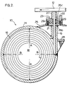
- Fig 2 is a sectional view of the conveyor scraper shown in Figure 1, taken along line A-A;
- Fig 3 is a top plan view of the sealing means of the presently preferred embodiment of the subject invention;
- Fig 4 is a sectional view taken along line A-A of Fig 3; and
- Fig 5 is a sectional view taken along line B-B of Fig 3.
- Referring to Figs 1 and 2,
conveyor scraper 10 compriseshousing 14 and wearelement 16.Housing 14 includes astorage chamber 18 and dispensing means 22.Wear element 16 is adapted to be stored instorage chamber 18 and dispensed throughdispensing means 22.Housing 14 has a closedend 15 and anopen end 17 which is adapted to be sealed in a pressure-tight fashion byaccess flange 24, which may take the form of a Victaulic (trademark) coupling.Storage chamber 18 is preferably made from a section of large diameter metal pipe of sufficient strength to withstand suitable operating pressures, which may range up to 100 psi (690 kN/sm) or more. - Dispensing means 22 of
housing 14 comprises alower section 19 welded tostorage portion 18,seal flange 21 welded onto the top oflower section 19, removableseal retainer plate 23, andtop section 27.Lower section 19 has a slot therein for receivingwear element 16.Seal flange 21 includes a cavity for receiving pressure sealing means in the form of alip seal 26 which seals offstorage chamber 18 ofhousing 14 from the outside when wear element is within the slot of dispensing means 22.Seal retainer plate 23 includes a cavity for receivinglip seal 26, and is designed to be coupled toseal flange 21 by a plurality ofcap screws 29.Top section 27 is welded onto the top ofseal retainer 23, and is provided with a dispensing slot which is in alignment with the slot oflower section 19 whenseal retainer 23 is screwed in place.Lip seal 26 is a continous seal which extends around the entire periphery of the dispensing slot.Lip seal 26 comprises abody portion 26a which is clamped securely betweenseal flange 21 andseal retainer 23, insidepressure sealing lip 26b and outside dust andwater sealing lip 26c.Reinforcement members housing 14 is pressurized.Lip seal 26 is preferably made from polyurethane, but other materials, such as rubber, could be used. -
Wear element 16 is a sheet of flexible material capable of being stored in thestorage chamber 18 ofhousing 14, preferably in a coiled fashion.Wear element 16 is preferably made from a polyurethane, such Thompson Gordon Thor-Flex 109H - A, which has been found to provide good scraping action without damage to the conveyor belt surface, and long wear life. As shown in Fig 1, theedges 32 ofwear element 16 have rounded corners which mate with the corners oflip seal 26 in a pressure-tight fashion. The dimensions ofwear element 16 will vary, depending upon the applications, but just to give one example, a 1/4 inch (6mm) thick polyurethane wear element having a width of 32 inches (81cm) and a length of approximately 118 inches (3m) may be stored in a storage chamber having a diameter of 8 inches (20cm), and has been found to be suitable for a number of conveyor applications. - Closed
end 15 ofhousing 14 is provided with anair inlet valve 34, to allowhousing 14 to be filled with compressed air.Housing 14 is pressure-tight up to a suitable internal operating pressure, whenopen end 17 is sealed byaccess flange 24 and wearelement 16 is withinlip seal 26, andhousing 14 is filled with a compressed fluid, such as air, and here it should be understood that the term "fluid" refers to both gases and liquids. An internal operating air pressures of 20-100 psi (138-690 kN/sm) has been found to be suitable, but higher or lower pressures may be appropriate, depending upon the desired scraping pressure. - The transverse dimensions A and B of
storage chamber 18 are selected to be less than the length ofwear element 16, so as to result in a relatively compact scraper capable of storing a relatively long wear element in a coiled fashion. In the preferred embodiment the inside surface ofstorage chamber 18 is cylindrical, in which case the aforesaid transverse dimensions A and B would of course represent the inside diameter of the cylinder, but housings having inside surfaces of non-cylindrical geometry could also be used. - In operation,
conveyor scraper 10 is mounted in its working position adjacent conveyor belt 12, as shown in Fig 2 (the arrow represents the direction of conveyor belt travel) such that wearelement 16 extends across the width of the conveyor belt.Housing 14 is then pressurized by compressed air from an outside source, through a pressure regulating valve up to a suitable internal operating pressure (which as discussed above may be 100 psi (690 kN/sm) or more). A 100 psi pressure produces a force of up to 800 pounds (3560 N) on a 1/4 inch (6mm) by 32 inch (81cm) wear element. The compressed air insidestorage chamber 18 acts directly on the wear element so as to uncoil the wear element and to force it out ofhousing 14 and against the surface of conveyor belt 12. The pressure seal provided bylip seal 26 inside dispensing means 22 maintains the inside air pressure while at the same time allowing for movement of the wear element relative to the dispensing means 22 of thehousing 14. As the wear element wears, the compressed air forces the coiled wear element to uncoil and its outside end to be urged against the conveyor belt, at an acceptably high relatively constant scraping pressure (the actual pressure being exerted by the wear element on the conveyor belt) throughout the lifetime of the wear element. For example, a suitable scraping pressure might be 60 psi (414 kN/sm), depending upon the material being conveyed, the speed of the belt, the angle of scraper contact, desired wear element lifetime and other factors. - Wear
element 16 can be loaded intohousing 14 in a number of ways. For example, wearelement 16 could be annually loaded by removingaccess flange 24 and placingwear element 16 insidestorage chamber 18 in a pre-coiled state, and then by feeding the outside end ofwear element 16 into dispensing means 22past seal 26. Alternatively, wearelement 16 could be fed backwards through the slot in dispensing means 22 whilehousing 14 is unpressurized, and then coiled up upon itself, preferably by a mechanical loading device. A suitable loading device is an elongated bar, having a longitudinal slot for holding the inside end ofwear element 16, and being provided at one end with a hand crank and at the other end with means for mating with a centering nipple or the like extending from the inside surface ofclosed end 15 ofhousing 14. - Figs 3, 4 and 5 illustrate the presently preferred embodiment of the pressure sealing means of the present invention. Such pressure sealing means takes the form of floating double lip pressure sealing means 40, comprising
seal body 41 andpressure lips Body 41 is a continuous ring of a suitably rigid sealing material such as urethane, in the shape of an elongate oval conforming to the the circumference ofwear element 16. The cross-section ofbody 41 is dimensioned to be slidingly received withincavity 44 which is formed whenseal retainer 45 is coupled to sealflange 46. In the embodiment illustrated,seal body 41 takes the form of a block of urethane, havinglips Lip 42 extends from the inside corner ofbody 41 proximate wear element 16 (i.e. the corner nearest storage chamber 18) and is formed to bear against the surface ofwear element 16 when air or other fluid pressure is applied thereto. Similarly,lip 43 extends from the diagonally opposed corner ofbody 41 and is formed to bear against the portion ofseal retainer 45 which forms the ceiling ofcavity 44. Also shown in figs 4 and 5 isdust seal 47, in the form of a resilient boot, which inhibits dust from coming in contact with pressure sealing means 40. - In operation, when
storage chamber 18 is pressurized, pressurized air fillscavity 44, and air pressure forceslip 42 againstwear element 16 andlip 43 againstseal retainer 45, because the air pressure on the facing surfaces oflips wear element 16 expands and contracts in response to ambient temperature variations, double lip sealing means 40 "floats" withwear element 16, i.e. it moves in and out ofcavity 44, all the while providing the requisite sealing action. Accordingly, the use of a floating seal such as sealing means 40 enables the conveyor scraper of the present invention to be used in conjunction with conveyors situated in environments which incur significant shifts in ambient temperature (e.g. +/- 30 deg C). A floating seal such as sealing means 40 is necessary in such environments, since the coefficient of thermal expansion of urethane is much higher than that for steel, brass and other common metals, and the width ofwear element 16, which is preferably made of urethane, will vary considerably, as temperature changes occur. However, since the thickness ofwear element 16 is much less than its width, e.g. 1/4 inch (6mm) compared to 32 inches (81cm), it is not necessary to adapt sealing means 40 to "float" any appreciable distance along the side ofwear element 16. Therefore, as best shown in Fig 5,cavity 44 need not be as deep along the sides ofwear element 16 as it is at the corners ofwear element 16, and sealbody 41 will be correspondingly reduced in depth. - Wear
element 16 is preferably coated with a high viscosity lubricant as the wear element is being stored withinhousing 14, to reduce the internal drag pressure. Alternatively, the interior surface ofstorage chamber 18 could be provided with grooves or lands or other means for offsetting the wear element from the inside surface of the housing. - It should be appreciated that the use of a relatively long, coiled scraper blade drastically reduces wastage, compared to most prior art designs, which is a significant advantage of the present invention since polyurethanes are very expensive by volume. In the subject design, it is expected that less than two inches (5cm) of a 118 inch (3m) scraper blade would be wasted, representing less than a two per cent wastage. Furthermore the compact design of the present invention enables the scraper to be mounted in conveyor chutes of limited dimensions, and at the same time, the high capacity of the conveyor scraper drastically reduces the labour cost involved in replacing the scraper blade, compared with prior art designs.
- In an alternative embodiment, the wear element is made up of two layers of polyurethane having different wear characteristics. Since the scraping action occurs at the leading edge of the wear element, the leading edge is preferably made from a layer of polyurethane which is relatively hard, for resisting abrasion. The trailing edge of the wear element is preferably made from a relatively soft polyurethane, to remove the dirt and other particulate matter that gets past the hard leading edge, while at the same time providing support of a rigidity sufficient to prevent excessive deflection of the thinner hard wearing element.
- It will be apparent that while the preferred embodiment of the invention utilizes the pneumatic force created by compressed air, other gases could be used. Similarly,
housing 14 could be filled with compressed water or other fluid, in which case the forces acting directly on the portion of the wear element coiled inside the housing would be hydraulic rather than pneumatic. It will also be appreciated that other pressure sealing arrangements could be used in place oflip seal 26, or floatingseal 40, such as one or more O-rings. It should be clear as well that while the housing of the preferred embodiment has a storage chamber which is cylindrical in shape, storage chambers having other geometrical configurations could conceivably be used. - It will therefore be appreciated by those skilled in the art that while the subject invention has been described and illustrated with respect to various preferred and alternative embodiments, various modifications of these embodiments may be made without departing from the subject invention, the scope of which is defined in the appended claims.
Claims (17)
- Apparatus for scraping a conveyor belt, wherein:
the apparatus includes a wear element (16), having an end portion which is arranged for direct scraping engagement against the working surface of a moving conveyor belt (12);
the apparatus includes walls defining a fluid-tight storage chamber (14), having a hollow interior (18);
the apparatus includes a means (34) for admitting a fluid under pressure into the hollow interior of the chamber (14);
characterised:
in that the walls defining the chamber (14) define an opening to the chamber, the opening being so shaped and dimensioned as to allow the wear element (16) to pass therethrough;
in that the apparatus is arranged with the end portion of the wear element (16) protruding from the opening, the rest of the wear element (16) being contained within the hollow interior (18) of the storage chamber (14);
in that the apparatus includes a sealing means (26), which is so arranged as to provide a fluid-tight seal between the wear element (16) and the walls of the opening, and to maintain that seal while allowing the wear element (16) to pass through the opening;
in that the arrangement of the apparatus is such that when fluid pressure is applied to the hollow interior (18) of the chamber (14), that same pressure acts upon the wear element to urge the element (16) out of the chamber (14), through the opening;
in that the arrangement of the apparatus is such that when fluid pressure is applied to the hollow interior (10) of the chamber (14), that same pressure acts directly upon the seal (26), and the arrangement is such that the seal (26) serves to prevent leakage of the pressurised fluid out through the opening, from the hollow interior (18) of the chamber (14);
and in that the arrangement of the apparatus is such that the wear element (16) operates in the manner of a fluid pressure operated piston that is sealingly slidable with respect to the opening. - Apparatus of claim 1, further characterised:
in that the wear element is of sheet material (16);
in that the wear element (16) has a working length, being that dimension of the sheet material (16) that reduces as the wear element (16) wears;
in that the cross-sectional shape and size of the sheet material, as measured in the plane lying normal to the working length, is complementary to the cross-sectional shape and size of the opening;
and in that the cross-sectional shape and size of the sheet material is the same at all points along the working length. - Apparatus of claim 1, further characterised in that the wear element comprises a single piece of sheet material (16), and that single piece is of sufficient width as to extend across substantially the whole width of the belt (12).
- Apparatus of claim 1, further characterised in that the walls of the opening are provided with reinforcement means (25,28), which are of sufficient strength and rigidity to substantially prevent the walls of the opening from being dimensionally distorted under the action of the applied pressure.
- Apparatus of claim 1, further characterised in that the fluid tight storage chamber (14) includes an access opening, which is normally closed by a detachable flange (24), and through which the element (16) is insertable into the chamber (14).
- Apparatus of claim 1, further characterised:
in that the sealing means comprises a seal element (40) of elastomeric material, which is mounted within the walls of the opening;
in that the seal element includes a seal lip (42) is so arranged and configured as to lie in contact with the wear element (16) around the full periphery of the cross-section of the wear element (16);
and in that the shape and size of the seal element is such as to provide inherently a gentle contact force between the seal lip (42) and the wear element (16), and the configuration of the apparatus is such that the contact force is increased as the fluid pressure is increased. - Apparatus of claim 6, further characterised in that the apparatus includes a supplementary dust lip (47), which is located between the seal lip (42) and the belt (12), the supplementary lip (47) being so configured and arranged as to resist the ingress of dust and dirt to the seal lip (42).
- Apparatus of claim 1, further characterised in that the material of the wear element (16) is flexible.
- Apparatus of claim 1, further characterised in that the compressed fluid forces the wear element(16) against the conveyor belt (12) at a substantially constant belt pressure above a pre-selected minimum scraping pressure value above 15 psi (100 kN/m²).
- Apparatus of claim 1, further characterised in that the sealing means comprises a lip seal having a body shaped to be secured to the said walls defining the opening and a first lip (42) shaped to bear against the periphery of the wear element (16) in a pressure-sealing fashion while providing for movement of the wear element (16) relative to the said walls as the wear element (16) wears.
- Apparatus of claim 1, further characterised in that the sealing means comprises floating sealing means (41) adapted to move in conjunction with the wear element (16) and to provide sealing action as the wear element (16) expands and contracts with temperature variations.
- Apparatus of claim 1, further characterised in that the sealing means comprises floating sealing means, which includes a double lip pressure seal having a body adapted to move freely within a seal cavity formed in a seal retaining portion of the walls defining the opening, a first pressure lip extending from the body and shaped to bear against the wear element in a pressure sealing fashion, and a second pressure lip extending from the body and shaped to bear against a ceiling of the seal cavity in a pressure sealing fashion.
- Apparatus of claim 12, further characterised in that the first pressure lip extends from a corner of the body nearest the storage chamber and the second pressure lip extends from a diagonally opposed corner of the body.
- Apparatus of claim 1, further characterised in that the wear element comprises a leading edge layer made from a relatively hard material and a trailing edge layer made from a softer material.
- Apparatus of claim 1, further characterised in that the storage chamber includes means for offsetting the wear element from the inside surface of the housing.
- Apparatus of claim 1, further characterised in that the transverse dimensions of the interior of the housing are less than the length of the wear element.
- Apparatus of claim 16, further characterised in that the storage chamber is configured to store the wear element in a coiled fashion.
Priority Applications (1)
| Application Number | Priority Date | Filing Date | Title |
|---|---|---|---|
| AT89904106T ATE90066T1 (en) | 1988-03-03 | 1989-03-02 | SCRATCHES FOR CONVEYOR BELTS. |
Applications Claiming Priority (2)
| Application Number | Priority Date | Filing Date | Title |
|---|---|---|---|
| CA000560512A CA1284307C (en) | 1988-03-03 | 1988-03-03 | Conveyer belt scraper |
| CA560512 | 1988-03-03 |
Publications (2)
| Publication Number | Publication Date |
|---|---|
| EP0402413A1 EP0402413A1 (en) | 1990-12-19 |
| EP0402413B1 true EP0402413B1 (en) | 1993-06-02 |
Family
ID=4137560
Family Applications (1)
| Application Number | Title | Priority Date | Filing Date |
|---|---|---|---|
| EP89904106A Expired - Lifetime EP0402413B1 (en) | 1988-03-03 | 1989-03-02 | Conveyor belt scraper |
Country Status (8)
| Country | Link |
|---|---|
| US (2) | US4877122A (en) |
| EP (1) | EP0402413B1 (en) |
| AU (1) | AU615289B2 (en) |
| BR (1) | BR8907307A (en) |
| CA (1) | CA1284307C (en) |
| DE (1) | DE68906887T2 (en) |
| WO (1) | WO1989008065A1 (en) |
| ZA (1) | ZA891611B (en) |
Families Citing this family (12)
| Publication number | Priority date | Publication date | Assignee | Title |
|---|---|---|---|---|
| US4944386A (en) * | 1990-01-08 | 1990-07-31 | Martin Engineering Company | Scraper for conveyor belts |
| DE4022097A1 (en) * | 1990-07-11 | 1992-01-16 | Voith Gmbh J M | Squeegee holder for a coating device |
| CA2055538A1 (en) * | 1990-11-15 | 1992-05-16 | Toyoshige Mohri | Belt cleaner for conveyor |
| GR1001463B (en) * | 1992-05-27 | 1994-01-31 | Christoforos Mayromatidis | Recycled laced belt plastic scraper originating from a process involving the autogenous welding of the elastomeric polyurethane plastic scraping residues. |
| GB9221426D0 (en) * | 1992-10-13 | 1992-11-25 | Morin Normand J | Conveyor belt scraper |
| GB9221902D0 (en) * | 1992-10-19 | 1992-12-02 | Morin Normand J | Coiled blade assembly for belt scraper |
| GB9221901D0 (en) * | 1992-10-19 | 1992-12-02 | Morin Normand J | Conveyor belt scraper |
| US5782976A (en) * | 1997-06-27 | 1998-07-21 | Westvaco Corporation | Continuous coater blade |
| EP0947452B1 (en) * | 1998-03-31 | 2003-05-21 | Maschinenbau Krumscheid GmbH | Cleaning device for conveyor belts |
| WO2007075880A2 (en) * | 2005-12-21 | 2007-07-05 | Martin Engineering Company | Conveyor belt cleaner including a scraper blade mounting apparatus having a biasing member |
| US9530527B2 (en) * | 2009-07-23 | 2016-12-27 | Areva Inc. | Advanced fuel CRUD sampling tool method |
| CN114875227A (en) * | 2022-04-11 | 2022-08-09 | 安徽澳新工具有限公司 | Heat treatment tool for hammer head machining |
Family Cites Families (26)
| Publication number | Priority date | Publication date | Assignee | Title |
|---|---|---|---|---|
| US2545882A (en) * | 1946-10-25 | 1951-03-20 | Hall Harry | Apparatus for scraping and cleaning conveyer belts |
| DE1051725B (en) * | 1955-03-02 | 1959-02-26 | Esch Werke K G Maschinenfabrik | Cleaning device for belt conveyor |
| FR1378871A (en) * | 1963-07-18 | 1964-11-20 | Michelin & Cie | Further training in conveyor belt installations |
| DE2012598A1 (en) * | 1970-03-17 | 1971-10-21 | Voith Gmbh J M | Smoothing doctor coating device |
| US3688336A (en) * | 1970-07-16 | 1972-09-05 | Lodding Engineering Corp | Extended-life doctoring apparatus |
| GB1416161A (en) * | 1972-01-01 | 1975-12-03 | Winterburn Ltd Joseph | Roll doctor apparatus |
| DE7238495U (en) * | 1972-10-20 | 1973-01-18 | Pott R | SCRAPER FOR CONVEYOR SYSTEMS |
| US3949866A (en) * | 1973-09-03 | 1976-04-13 | Contico Industries Ltd. | Conveyer scraper with continuously applied constant surface pressure |
| US4036351A (en) * | 1976-02-12 | 1977-07-19 | Material Control, Inc. | Conveyor belt cleaner |
| US4257517A (en) * | 1976-12-06 | 1981-03-24 | Uniroyal Ltd. | Scraper bars for use with conveyor belting and the like |
| SE423703B (en) * | 1976-12-17 | 1982-05-24 | Trelleborg Ab | ENDLESS TRANSPORT BELT REMOVAL |
| US4105109A (en) * | 1977-03-04 | 1978-08-08 | Schultz John J | Scraper cleaning apparatus for endless conveyor belt |
| US4202437A (en) * | 1977-10-06 | 1980-05-13 | Gordon James R | Scraper assembly for a conveyor belt |
| GB1549608A (en) * | 1978-02-24 | 1979-08-08 | Gilpin J | Scrapers for conveyor belts |
| ZA783442B (en) * | 1978-06-15 | 1979-07-25 | W Veenhof | Improved conveyor belt cleaner |
| US4328888A (en) * | 1978-06-20 | 1982-05-11 | Luke Richard F | Conveyor belt scraper blades |
| FR2439148A1 (en) * | 1978-10-20 | 1980-05-16 | Salgar Supplies | ADJUSTABLE SCRAPER FOR CLEANING CONVEYOR BELTS |
| US4349098A (en) * | 1979-09-07 | 1982-09-14 | Veenhof Willem D | Conveyor belt cleaning or scraping devices |
| US4269301A (en) * | 1979-10-22 | 1981-05-26 | Gibbs Alfred S | Conveyor belt scraper system |
| US4367120A (en) * | 1980-03-13 | 1983-01-04 | Vickerys Limited | Doctor blade mounting assembly |
| DE3022955C2 (en) * | 1980-06-19 | 1982-12-16 | Jagenberg-Werke AG, 4000 Düsseldorf | Device for regulating the application thickness when coating moving material webs |
| US4520917A (en) * | 1982-03-03 | 1985-06-04 | Thomas J. Wright | Conveyor belt cleaning methods and apparatuses therefor |
| US4489823A (en) * | 1982-08-09 | 1984-12-25 | Gordon James R | Scraper blade for a belt conveyor |
| US4541523A (en) * | 1983-08-04 | 1985-09-17 | Stockton Neville R T | Conveyor belt scraper |
| US4598823A (en) * | 1984-02-13 | 1986-07-08 | Martin Engineering Company | Conveyor belt cleaner |
| SU1239051A2 (en) * | 1984-12-24 | 1986-06-23 | Белгородский филиал Всесоюзного проектно-конструкторского технологического института атомного машиностроения и котлостроения | Device for cleaning conveyer belt |
-
1988
- 1988-03-03 CA CA000560512A patent/CA1284307C/en not_active Expired - Lifetime
- 1988-05-02 US US07/189,239 patent/US4877122A/en not_active Expired - Fee Related
-
1989
- 1989-03-02 DE DE89904106T patent/DE68906887T2/en not_active Expired - Lifetime
- 1989-03-02 ZA ZA891611A patent/ZA891611B/en unknown
- 1989-03-02 AU AU33420/89A patent/AU615289B2/en not_active Ceased
- 1989-03-02 BR BR898907307A patent/BR8907307A/en not_active IP Right Cessation
- 1989-03-02 EP EP89904106A patent/EP0402413B1/en not_active Expired - Lifetime
- 1989-03-02 WO PCT/GB1989/000218 patent/WO1989008065A1/en active IP Right Grant
- 1989-08-31 US US07/367,361 patent/US5048667A/en not_active Expired - Fee Related
Also Published As
| Publication number | Publication date |
|---|---|
| WO1989008065A1 (en) | 1989-09-08 |
| DE68906887T2 (en) | 1994-01-05 |
| AU615289B2 (en) | 1991-09-26 |
| CA1284307C (en) | 1991-05-21 |
| EP0402413A1 (en) | 1990-12-19 |
| US5048667A (en) | 1991-09-17 |
| AU3342089A (en) | 1989-09-22 |
| DE68906887D1 (en) | 1993-07-08 |
| US4877122A (en) | 1989-10-31 |
| BR8907307A (en) | 1991-03-19 |
| ZA891611B (en) | 1990-11-28 |
Similar Documents
| Publication | Publication Date | Title |
|---|---|---|
| EP0402413B1 (en) | Conveyor belt scraper | |
| US5169160A (en) | Lubricating seal for pneumatic cylinder | |
| EP0513480A1 (en) | Ink unit for printing press and method | |
| US4703915A (en) | Knife gate valve with semi-hard, resilient seat | |
| GB2081662A (en) | Conveyor belt cleaning device | |
| JPH06328671A (en) | Wedge type ink containing part device for printing press | |
| US7648019B2 (en) | Conveyor belt scraper | |
| EP0012594B1 (en) | Self purging seal | |
| EP0035854B1 (en) | Flow control valve assembly | |
| CA2216373C (en) | Reversible scraper blade for cleaning conveyor belt | |
| CN115210155A (en) | Conveyor belt cleaning equipment | |
| RU2031064C1 (en) | Conveyor belt cleaning device | |
| US20010021284A1 (en) | Hydrostatic bearing device | |
| US6821097B2 (en) | Concrete pump with S-tube valve assembly with wear ring-spring-retainer ring construction | |
| US7000899B2 (en) | Shutoff device | |
| AU6857781A (en) | Slurry pump | |
| US5372244A (en) | Conveyor belt scraper | |
| EP0776435B1 (en) | Adaptation for tightening a lead-through member | |
| EP0881417B1 (en) | Aerator valve assembly | |
| EP0502810A1 (en) | Linear drive with cylinder without piston rod | |
| JPH03505567A (en) | conveyor belt scraper | |
| JP6993103B2 (en) | Ring dust strip and sealing device | |
| SU870826A1 (en) | Locking control valve | |
| KR950006387Y1 (en) | Valve switching over device for viscous matenal | |
| EP0498627A2 (en) | Improvements in or relating to seals |
Legal Events
| Date | Code | Title | Description |
|---|---|---|---|
| PUAI | Public reference made under article 153(3) epc to a published international application that has entered the european phase |
Free format text: ORIGINAL CODE: 0009012 |
|
| 17P | Request for examination filed |
Effective date: 19900831 |
|
| AK | Designated contracting states |
Kind code of ref document: A1 Designated state(s): AT BE DE FR GB IT SE |
|
| 17Q | First examination report despatched |
Effective date: 19911028 |
|
| RAP1 | Party data changed (applicant data changed or rights of an application transferred) |
Owner name: MORIN, NORMAND JOSEPH Owner name: ASQUITH, ANTHONY |
|
| RAP3 | Party data changed (applicant data changed or rights of an application transferred) |
Owner name: MORIN, NORMAND JOSEPH Owner name: ASQUITH, ANTHONY |
|
| GRAA | (expected) grant |
Free format text: ORIGINAL CODE: 0009210 |
|
| AK | Designated contracting states |
Kind code of ref document: B1 Designated state(s): AT BE DE FR GB IT SE |
|
| REF | Corresponds to: |
Ref document number: 90066 Country of ref document: AT Date of ref document: 19930615 Kind code of ref document: T |
|
| REF | Corresponds to: |
Ref document number: 68906887 Country of ref document: DE Date of ref document: 19930708 |
|
| ITF | It: translation for a ep patent filed |
Owner name: JACOBACCI CASETTA & PERANI S.P.A. |
|
| ET | Fr: translation filed | ||
| PGFP | Annual fee paid to national office [announced via postgrant information from national office to epo] |
Ref country code: BE Payment date: 19940314 Year of fee payment: 6 |
|
| PLBE | No opposition filed within time limit |
Free format text: ORIGINAL CODE: 0009261 |
|
| STAA | Information on the status of an ep patent application or granted ep patent |
Free format text: STATUS: NO OPPOSITION FILED WITHIN TIME LIMIT |
|
| 26N | No opposition filed | ||
| EAL | Se: european patent in force in sweden |
Ref document number: 89904106.5 |
|
| PG25 | Lapsed in a contracting state [announced via postgrant information from national office to epo] |
Ref country code: BE Effective date: 19950331 |
|
| BERE | Be: lapsed |
Owner name: MORIN NORMAND JOSEPH Effective date: 19950331 Owner name: ASQUITH ANTHONY Effective date: 19950331 |
|
| PGFP | Annual fee paid to national office [announced via postgrant information from national office to epo] |
Ref country code: GB Payment date: 19960229 Year of fee payment: 8 |
|
| PGFP | Annual fee paid to national office [announced via postgrant information from national office to epo] |
Ref country code: AT Payment date: 19960327 Year of fee payment: 8 |
|
| PG25 | Lapsed in a contracting state [announced via postgrant information from national office to epo] |
Ref country code: GB Effective date: 19970302 Ref country code: AT Effective date: 19970302 |
|
| PGFP | Annual fee paid to national office [announced via postgrant information from national office to epo] |
Ref country code: SE Payment date: 19970306 Year of fee payment: 9 |
|
| GBPC | Gb: european patent ceased through non-payment of renewal fee |
Effective date: 19970302 |
|
| PGFP | Annual fee paid to national office [announced via postgrant information from national office to epo] |
Ref country code: FR Payment date: 19980206 Year of fee payment: 10 |
|
| PG25 | Lapsed in a contracting state [announced via postgrant information from national office to epo] |
Ref country code: SE Free format text: LAPSE BECAUSE OF NON-PAYMENT OF DUE FEES Effective date: 19980303 |
|
| EUG | Se: european patent has lapsed |
Ref document number: 89904106.5 |
|
| PGFP | Annual fee paid to national office [announced via postgrant information from national office to epo] |
Ref country code: DE Payment date: 19990305 Year of fee payment: 11 |
|
| PG25 | Lapsed in a contracting state [announced via postgrant information from national office to epo] |
Ref country code: FR Free format text: LAPSE BECAUSE OF NON-PAYMENT OF DUE FEES Effective date: 19991130 |
|
| REG | Reference to a national code |
Ref country code: FR Ref legal event code: ST |
|
| PG25 | Lapsed in a contracting state [announced via postgrant information from national office to epo] |
Ref country code: DE Free format text: LAPSE BECAUSE OF NON-PAYMENT OF DUE FEES Effective date: 20010103 |
|
| PG25 | Lapsed in a contracting state [announced via postgrant information from national office to epo] |
Ref country code: IT Free format text: LAPSE BECAUSE OF NON-PAYMENT OF DUE FEES;WARNING: LAPSES OF ITALIAN PATENTS WITH EFFECTIVE DATE BEFORE 2007 MAY HAVE OCCURRED AT ANY TIME BEFORE 2007. THE CORRECT EFFECTIVE DATE MAY BE DIFFERENT FROM THE ONE RECORDED. Effective date: 20050302 |