EP0402409B1 - Inertialwaage mit gefesselter linearbewegung - Google Patents
Inertialwaage mit gefesselter linearbewegung Download PDFInfo
- Publication number
- EP0402409B1 EP0402409B1 EP89903615A EP89903615A EP0402409B1 EP 0402409 B1 EP0402409 B1 EP 0402409B1 EP 89903615 A EP89903615 A EP 89903615A EP 89903615 A EP89903615 A EP 89903615A EP 0402409 B1 EP0402409 B1 EP 0402409B1
- Authority
- EP
- European Patent Office
- Prior art keywords
- suspension system
- weighing platform
- support members
- platform
- framework
- Prior art date
- Legal status (The legal status is an assumption and is not a legal conclusion. Google has not performed a legal analysis and makes no representation as to the accuracy of the status listed.)
- Expired - Lifetime
Links
- 238000005303 weighing Methods 0.000 claims abstract description 63
- 239000000725 suspension Substances 0.000 claims abstract description 39
- 230000010355 oscillation Effects 0.000 claims abstract description 12
- 230000001419 dependent effect Effects 0.000 claims abstract description 7
- 239000012530 fluid Substances 0.000 claims description 9
- 238000005452 bending Methods 0.000 claims description 7
- 239000000463 material Substances 0.000 claims description 5
- 238000005259 measurement Methods 0.000 description 16
- 230000035945 sensitivity Effects 0.000 description 10
- 238000013016 damping Methods 0.000 description 4
- 238000006073 displacement reaction Methods 0.000 description 4
- 230000008901 benefit Effects 0.000 description 3
- 239000011521 glass Substances 0.000 description 3
- 230000001133 acceleration Effects 0.000 description 2
- 230000009471 action Effects 0.000 description 2
- 230000007812 deficiency Effects 0.000 description 2
- 230000005484 gravity Effects 0.000 description 2
- 230000003287 optical effect Effects 0.000 description 2
- 239000002245 particle Substances 0.000 description 2
- 230000009467 reduction Effects 0.000 description 2
- 230000006641 stabilisation Effects 0.000 description 2
- 238000011105 stabilization Methods 0.000 description 2
- 238000013459 approach Methods 0.000 description 1
- 230000002238 attenuated effect Effects 0.000 description 1
- 230000008859 change Effects 0.000 description 1
- 238000010276 construction Methods 0.000 description 1
- 230000007423 decrease Effects 0.000 description 1
- 238000013461 design Methods 0.000 description 1
- 230000005284 excitation Effects 0.000 description 1
- 239000007789 gas Substances 0.000 description 1
- 230000006872 improvement Effects 0.000 description 1
- 230000003993 interaction Effects 0.000 description 1
- 238000012423 maintenance Methods 0.000 description 1
- 230000014759 maintenance of location Effects 0.000 description 1
- 239000002184 metal Substances 0.000 description 1
- 230000004048 modification Effects 0.000 description 1
- 238000012986 modification Methods 0.000 description 1
- 238000005457 optimization Methods 0.000 description 1
- 230000003534 oscillatory effect Effects 0.000 description 1
- 238000012545 processing Methods 0.000 description 1
- 239000007787 solid Substances 0.000 description 1
- 239000000758 substrate Substances 0.000 description 1
- 238000012360 testing method Methods 0.000 description 1
Images


Classifications
-
- G—PHYSICS
- G01—MEASURING; TESTING
- G01G—WEIGHING
- G01G3/00—Weighing apparatus characterised by the use of elastically-deformable members, e.g. spring balances
- G01G3/12—Weighing apparatus characterised by the use of elastically-deformable members, e.g. spring balances wherein the weighing element is in the form of a solid body stressed by pressure or tension during weighing
-
- G—PHYSICS
- G01—MEASURING; TESTING
- G01G—WEIGHING
- G01G21/00—Details of weighing apparatus
- G01G21/24—Guides or linkages for ensuring parallel motion of the weigh-pans
-
- G—PHYSICS
- G01—MEASURING; TESTING
- G01G—WEIGHING
- G01G3/00—Weighing apparatus characterised by the use of elastically-deformable members, e.g. spring balances
- G01G3/12—Weighing apparatus characterised by the use of elastically-deformable members, e.g. spring balances wherein the weighing element is in the form of a solid body stressed by pressure or tension during weighing
- G01G3/16—Weighing apparatus characterised by the use of elastically-deformable members, e.g. spring balances wherein the weighing element is in the form of a solid body stressed by pressure or tension during weighing measuring variations of frequency of oscillations of the body
Definitions
- This invention relates generally to inertial balances used to measure mass and more particularly, to a suspension system for an inertial balance which improves the measurement accuracy of such instruments.
- Inertial balances can measure mass in the absence of gravity and are therefore especially well suited for applications in space and also in industrial situations where gravitational balances are not practical.
- An inertial measurement device relates the force on a sample to the acceleration experienced by the sample in order to determine its mass. As a practical matter, most inertial balances induce force and acceleration by vibrational means.
- U.S. Patent 3,926,271 describes one such inertial balance in which a free end of a tapered tubular element, which is clamped at its other end, is oscillated along an arc to determine the mass of a specimen supported on the free end. The specimen's mass is determined by measuring the resonant frequency of the tapered tubular element which changes in accordance with the mass loading.
- This earlier developed inertial balance is characterized by extremely high sensitivity and accordingly has been widely used as a microbalance, i.e. to measure the mass of small particles.
- An adaption of the instrument to measure the mass of matter suspended within a fluid medium is described in U.S. Patent 4,391,2338.
- the tapered element oscillating microbalance described above exhibits high sensitivity, its measurement accuracy is limited. In such an instrument, sensitivity depends upon how much frequency shift is obtained for a certain change in sample mass. Accuracy, on the other hand, relates to the correlation between the results provided by the instrument in comparison to an established standard weight, e.g. one traceable to the National Bureau of Standards. The low mass and particular configuration of the earlier developed instrument results in its high sensitivity. Unfortunately, however, displacement of the center of mass of the object being weighed can introduce an error in the measurement results. In other words, a simple reorientation of a test sample on the weighing platform can produce a different mass reading. This loss of accuracy due to displacement errors, is not especially significant when measuring small particles but becomes a major concern as the size of the sample increases. Moreover, this problem appears to be endemic to presently available inertial balances.
- U.S. Patent 3,595,329 describes an inertial weighing apparatus in which spaced apart bellows or spaced apart pairs of leaf springs form a compliant support for an axially vibrated shaft mounting a conical weighing pan. This suspension arrangement although adequate for certain applications, would exhibit significant measurement errors if the center of gravity of the mass to be weighed was displaced from the center line of the apparatus.
- U.S. Patent 4,158,395 relates to a "Weighing Device Using a Resonant Mass-Spring System" in which attempts are made to limit movement of an oscillating measurement platform to one degree of freedom.
- the measurement platform is suspended by two pairs of flexible struts anchored to a relatively heavy intermediate mass located on one side of the measurement platform.
- the intermediate mass is itself suspended by struts intended to allow it to move substantially in only one degree of freedom.
- the relatively heavy intermediate mass acts as a damping reduction system to minimize energy loss from the oscillating measurement platform.
- the one-sided suspension system for the measurement platform described in this patent, causes the sample to move along an arc and introduces measurement errors and a mass resolution uncertainty.
- the suspension system includes a supporting framework, and a first plurality of at least three elongate support members, attached at their outer ends to said framework for suspending the weighing platform.
- the inner ends of said support members converge toward a first common point and the support members are advantageously disposed symmetrically about said first common point.
- the weighing platform is mounted to move in concert with said first point.
- the support members lie in a first common plane when the weighing platform is at rest and this plane is perpendicular to the direction along which the weighing platform is induced to oscillate.
- the so constructed suspension system serves to constrain the movement of the oscillating platform to uniform linear motion along this direction.
- the support members are elastic and operate primarily in a bending mode.
- the support elements are also preferably hollow and constructed of a glass material having a substantially temperature independent Young's modulus over the operating temperature range of the inertial balance. Additionally, the support members may be tapered and/or have an elliptical, rectangular or other elongated cross-sectional configuration.
- a second plurality of elongate support members disposed in a second common plane when the platform is at rest are provided.
- the second common plane is parallel to and spaced from the first common plane and the support members in this second common plane also each have an outer end secured to said framework and an inner end which converges toward a second common point.
- a stiff center rod preferably connects the first and second common points and also supports the weighing platform and facilitates inducement and maintenance of oscillation of the weighing platform at a resonant frequency dependent upon mass loading. Additional support struts may be provided between the center rod and the weighing platform to further stabilize the latter.
- each support member may be attached near its outer end to the framework by an associated support rod which is orthogonal to said member and coplanar with said member when the platform is at rest.
- An extension is provided on each of the support members extending radially outward beyond the associated support rod and a counterweight is attached to each such extension. The counterweights serve to maintain the center of mass of the weighing platform and suspending means fixed with respect to the supporting framework during platform oscillation.
- the supporting framework may be provided with a fluid port and at least a port ion of the center rod, a support member and a port ion of the framework are hollow and interconnected to provide a continuous fluid flow path from the weighing platform to said port.
- the weighing platform can comprise a fluid permeable filter.
- a principal object of the present invention is to improve the measurement accuracy of inertial balances.
- Another object of this invent ion is to provide an improved suspension system for a frequency dependent mass measuring unit.
- Yet another object of the present invention is to ensure the achievement of uniform linear motion at the weighing platform of an inertial balance.
- a further object is to provide an inertial balance which allows use of filters at the weighing platform or allows samples to be held on the platform by a pressure differential.
- a still further object is to provide a design for an accurate inertial balance which can be tailored to: reduce susceptibility to higher order vibrational modes, to reduce the moving mass of the balance and thereby increase its sensitivity, to minimize damping losses to the outside, and/or to produce a more temperature stable system.
- Still another object is to provide a highly accurate mass measuring instrument which can be constructed readily and cost effectively and which is susceptible to wide application.
- the present invention is based upon the realization that the measurement accuracy deficiencies common to existing inertial balances results from the non-linear motion experienced by the sample on the weighing platform of such balances. To overcome this problem, the present invention constrains the oscillatory movement of the weighing platform, and accordingly the sample, to uniform linear motion. This approach produces a substantial improvement in the accuracy of the inertial balance.
- a first embodiment of a linear motion constraining suspension system for an inertial balance is shown, in simplified form, in Figure 1.
- a sample table or weighing platform 12 is attached at the intersection of four symmetrically disposed, elongate, elastic support elements 14, 16, 18 and 20 arranged in a cross configuration or arrangement 10.
- the outer ends of the support members are, in turn, supported at equal distances from the intersection, in a manner which permits their operation in a bending mode (as indicated by the dashed lines).
- the four support members lie in a common plane when the weighing platform is at rest.
- a vibration of the platform is introduced in a direction perpendicular to the plane containing the support members, as indicated by double headed arrow V.
- the weighing platform 12 is constrained to undergo uniform linear motion.
- the number, form and orientation of the support members in the suspension system may vary from that shown in Figure 1 so long as the weighing platform 12 is constrained to experience uniform linear motion. It is possible, for example, to construct a symmetric suspension system with three or even two elongate support members. However, as the number of such members decreases, the possibility for the excitation of non-linear motion increases. This can be attenuated by using highly elliptical or flat elastic elements as the support members, as more fully discussed hereinafter. In some cases, it may even be possible to use a geometrically non-symmetric arrangement of the support members and still produce operational symmetry, i.e. substantially uniform linear motion of the weighing platform. A geometrically symmetrical arrangement of four identical support members spaced 90° apart is, however, presently preferred.
- the mass measurement accuracy of a vibratory inertial balance is dependent upon the precision with which linear motion is maintained at the weighing platform undergoing oscillation.
- a high mechanical Q aids the mass resolution of the system.
- the moving mass of the measuring system determines its sensitivity because the lower the oscillating system mass the greater the shift in frequency for a given sample mass.
- the primary purpose of this invention is to maximize the mass measurement accuracy of an inertial balance. Further refinements, described in detail hereinafter, permit concurrent optimization of the instrument's resolution and sensitivity.
- the second constraining arrangement of support members may be identical to that of the first arrangement 10 or may assume any of the various alternative forms discussed herein.
- the support members of arrangement 10' are coplanar when the weighing platform 12 is at rest and intersect at a common point P2.
- the common plane of arrangement 10' is parallel to and spaced from the common plane of arrangement 10.
- Stiff center member 22 connects the common intersection point P2 of arrangement 10' to the common intersection point P1 of arrangement 10.
- connecting member 22 extends along an axis which is parallel to the direct ion along which linear motion of the weighing platform occurs. Although this orientation is preferred, P2 could conceivably be offset with respect to P1.
- a supporting framework 24 provides overall structural support for the elongate support members that suspend weighing platform 12.
- the framework 24 may be made of any suitable material, e.g. glass or metal tubing and may take any of various forms, e.g. a rectangular structure as shown in Figure 3.
- weighing platform 12, employed to hold the sample whose mass is to be measured may comprise a table, substrate, filter or the like, having various shapes and constructions depending upon the particular application.
- Elongate elastic support members 14, 16, 18, and 20 are symmetrically disposed in a first cross configuration and lie in a first common plane when the weighing platform is at rest.
- Support members 14', 16', 18' and 20' are similarly arranged in a second cross configuration and lie in a second common plane when the weighing platform is at rest. This second common plane is parallel to but spaced from the first common plane.
- Each support member of the first cross configuration (shown in the top of Figure 3) is attached near its outer end to the framework 24 by an associated support rod 26 which is orthogonal to said member and coplanar with said member when the platform is at rest.
- the support members of the second cross configuration (shown near the bottom of Figure 3) are similarly attached to framework 24 by rods 26'.
- center rod 22 which is orthogonal to the planes of the cross configurations when the weighing platform 12 is at rest.
- Center rod 22 extends above the upper cross configuration to hold weighing platform 12.
- the center rod may also extend below the lower cross configuration to allow for interaction with a position sensor and vibration drive of a feedback system that induces and maintains the oscillation of the measuring platform 12 through the action of center rod 22.
- a detector of the position sensor and a drive coil of the vibrational drive of the feedback system are preferably attached in a fixed position, by conventional means (not shown) to the supporting framework 24.
- a typical feedback system 30 for use with a constrained linear motion inertial balance is shown in Figure 4.
- a drive coil 32 powered through amplifier 34 interacts with a permanent magnet 36 secured to center rod 22 to induce vibration of rod 22 and attached weighing platform 12.
- An optical pickup comprising, for example, a photodiode 38 energized from power supply 40 and a photodetector 42, interact with an opaque vane 41 attached to rod 22, to continually monitor the position of rod 22.
- An output signal from photodetector 42 is fed back to an amplifier 34 containing an automatic gain control for start-up and amplitude stabilization, and serves to ensure that rod 22 is maintained in oscillation at a resonant frequency dependent upon mass loading.
- a data processing unit 44 is connected to amplifier 34 and in known fashion determines changes in the resonant frequency of oscillation and indicates a corresponding mass loading of the weighing platform.
- other motion detector devices e.g. magnetic
- other vibration drive schemes may be employed and variations in the circuitry of the feedback system are contemplated.
- the drive and sensor elements of the feedback system may likewise be positioned to interact with other portions of rod 22.
- the illustrated embodiment demonstrates the most important features for a sensitive and accurate inertial mass balance.
- Of prime importance is the achievement of uniform linear motion at the weighing platform 12. This linear motion is ensured by the constraints imposed by the symmetric arrangement of the elongate support members. As already discussed, the double cross arrangement serves to cancel any torgue produced when the center of mass of the sample does not lie along the longitudinal axis defined by center rod 22.
- the instrument is constructed such that the moving parts, i.e. the elongate support members, center rod and weighing platform, have as minimal mass as practical consistent with the stresses produced by the mass of the samples that are to be weighed.
- the oscillation of the weighing platform is accommodated and constrained to uniform linear motion by the bending of the elongate support members.
- bending is preferred because of the high stability, in regard to sideways displacement, afforded thereby.
- a further refinement of the constrained linear motion inertial balance of the present invention can be achieved by utilizing hollow elongate support members. This has the advantage of reducing the moving mass of the balance, thereby increasing its sensitivity. It also has the advantage of allowing the transport of gases or other fluids through the support members.
- a suction action can be provided at the weighing platform by attaching a pump (not shown) to a fluid port or outlet 44. This permits the use of filters at the weighing platform or the retention of samples on the platform by a pressure differential.
- the elongate support members have a Young's modulus which is temperature dependent, frequency changes will result with temperature changes even with constant mass. Accordingly, in accordance with the principles of the present invention, the elongate support members are preferably constructed from a material, for example, a glass, with a temperature independent Young's modulus over the operating temperature range of the inertial balance, thereby resulting in a more temperature stable system.
- Figure 5 presents a top plan view of an embodiment of the constrained linear motion inertial balance of the present invention incorporating several additional refinements. These include utilization of elongate support members having a cross-sectional configuration which is elongated along a direction perpendicular to the longitudinal axis of the member and the direction of linear motion of platform 12.
- Figure 5A depicts a hollow elliptical cross-sectional configuration
- Figure 5B depicts a solid rectangular cross-sectional configuration.
- Such configurations provide a high mechanical constraint for the weighing platform with low restoring force for the vibration in comparison to circular cross section elements. This is particularly advantageous when lower resonant frequencies of linear motion inertial balances are desired such as when samples having low modulus of elasticity need to be measured.
- an extension 46 can be provided on each support member extending radially outward beyond the associate support rod 26, 26' and a counterweight 48 attached to each such extension.
- These counterweights are selected and employed to compensate for displacement of the center of mass of the moving portion of the inertial balance.
- Figure 6 schematically illustrates how counterweights 48 on extensions 46 of one set of opposed elongated support members 14, 18 mounted by support rods 26 to ridigly interconnected framework sections 24a, 24b, 24c and 24d, operate to provide cancellation of torque and fixation of the center of mass of the moving portion of the balance.
- Figure 7 illustrates a further refinement of the present invention in which a set of struts 50 can be connected between center rod 22 and the periphery or base of weighing platform 12 in order to provide additional support and stabilization to the platform.
- Figure 8 depicts in plan view another refinement of the present invent ion in which the elongate support members 14'', 16'', 18'' and 20'' are tapered from their outer ends (which can be directly connected to framework 24) towards their inner ends. This tapering reduces susceptibility to higher order vibrational modes and further reduces the moving mass of the balance.
Landscapes
- Physics & Mathematics (AREA)
- General Physics & Mathematics (AREA)
- Vibration Prevention Devices (AREA)
- Testing Of Balance (AREA)
Claims (20)
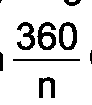
- Ein Aufhängungssystem zum Aufhängen einer Wiegeplattform in einer Inertialwaage, bei der diese Wiegeplattform (12) zum Oszillieren bei einer Resonanzfrequenz gebracht wird und Änderungen in der Resonanzfrequenz der Oszillation aufgrund von Massenbeladung der Wiegeplattform (12) erfaßt werden, wobei das Aufhängungssystem ein tragendes Stabwerk (24) und Aufhängevorrichtungen zum Aufhängen der Wiegeplattform (12) an dem tragenden Stabwerk (24) umfaßt, dadurch gekennzeichnet, daß die Aufhängevorrichtung die Plattform (12), wenn diese oszilliert, in der Bewegung bindet, damit sie gleichmäßige lineare Bewegung entlang einer gewünschten Richtung bezüglich des Stabwerks (24) ausübt, unabhängig von Massenorientierung und Stellung auf der Plattform (12), daß die Aufhängevorrichtung rückstellende Kräfte in Richtungen orthogonal zu der gewünschten Richtung ausübt, wobei die rückstellenden Kräfte um Größenordnungen größer als rückstellende Kräfte sind, die durch die Aufhängevorrichtung in der gewünschten Richtung ausgeübt werden, daß die Aufhängevorrichtung eine erste Vielzahl (10) von n langgestreckten stabartigen Traggliedern (14, 16, 18) umfaßt, wobei n gleich oder größer als drei ist, wobei jedes dieser Tragglieder ein äußeres Ende aufweist, das an dem Stabwerk (24) befestigt ist, und ein inneres Ende hat, das in Richtung auf einen ersten gemeinsamen Punkft (P1) konvergiert, und die Tragglieder der ersten Vielzahl (10) symmetrisch um diesen ersten gemeinsamen Punkt (P1) angeordnet sind, wobei benachbarte Glieder um
- Das Aufhängungssystem nach Anspruch 1, bei dem n gleich vier ist.
- Das Aufhängungssystem nach Anspruch 1, bei dem die Tragglieder der ersten Vielzahl in einer ersten gemeinsamen Ebene angeordnet sind, wenn die Wiegeplattform (12) in ruhe ist, die gleichmäßige lineare Bewegung entlang einer vorherbestimmten Richtung erfolgt und die erste gemeinsame Ebene senkrecht zu der vorherbestimmten Richtung ist.
- Das Aufhängungssystem nach Anspruch 3, bei dem die Tragglieder (14, 16, 18, 20) elastisch sind und primär in einem Biege-Modus arbeiten.
- Das Aufhängungssystem nach Anspruch 4, bei dem wenigstens eines dieser Tragglieder sich von seinem äußeren Ende in Richtung auf sein inneres Ende verjüngt.
- Das Aufhängungssystem nach Anspruch 4, bei dem eines dieser Tragglieder sich entlang einer Längsachse erstreckt und eine Querschnittskonfiguration aufweist, die langgestreckt ist entlang einer Richtung, die senkrecht zu der Längsachse und der vorherbestimmten Richtung ist.
- Das Aufhängungsystem nach Anspruch 6, bei dem das besagte eine Tragglied eine rechteckige Querschnittskonfiguration aufweist.
- Das Aufhängungssystem nach Anspruch 6, bei dem das besagte eine Tragglied eine elliptische Querschnittskonfiguration aufweist.
- Das Aufhängungssystem nach Anspruch 4, bei dem wenigstens eines dieser Tragglieder hohl ist.
- Das Aufhängungssystem nach Anspruch 4, bei dem die Tragglieder aus einem Material mit einem im wesentlichen temperaturunabhängigen Young-Modul über den Arbeitstemperaturbereich der Inertialwaage zusammengesetzt sind.
- Das Aufhängungssystem nach Anspruch 4, bei dem jedes Tragglied nahe seines äußeren Endes an dem Stabwerk durch einen zugeordneten Halterungsstab (26) angebracht ist, der rechtwinklig zu diesem Glied und koplanar mit diesem Glied ist, wenn sich die Plattform (12) in Ruhe befindet.
- Das Aufhängungssystem nach Anspruch 11, das weiterhin: eine Verlängerung (46) an jedem Tragglied, die sich radial nach außen bis über den zugeordneten Halterungsstab (26) hinaus erstreckt, und
ein Gegengewicht (48), das an jeder derartigen Verlängerung (46) angebracht ist, umfaßt, wobei die Gegengewichte dazu dienen, den Massenmittelpunkt der Wiegeplattform (12) aufrecht zu halten und die Aufhängevorrichtung bezüglich des tragenden Stabwerks (24) während der Plattformoszillation fixiert zu halten. - Das Aufhängungssystem nach Anspruch 3, das weiterhin eine zweite Vielzahl (10') von länglichen Traggliedern (14', 16', 18') umfaßt, die in einer zweiten gemeinsamen Ebene angeordnet sind, wenn sich die Plattform (12) in Ruhe befindet, wobei diese zweite gemeinsame Ebene parallel zu und beabstandet von der ersten gemeinsamen Ebene ist, die Tragglieder der besagten zweiten Vielzahl (10') jeweils ein äußeres Ende aufweisen, das an dem Stabwerk (24) befestigt ist, und ein inneres Ende besitzen, das in Richtung auf einen zweiten gemeinsamen Punkt (P2) konvergiert; und steife Verbindungseinrichtungen zum Verbinden des ersten gemeinsamen Punktes (P1) mit dem zweiten gemeinsamen Punkt (P2) umfaßt.
- Das Aufhängungssystem nach Anspruch 13, bei dem die steife Verbindungseinrichtung einen steifen Mittelstab (22) umfaßt, der starr zwischen dem ersten und dem zweiten Punkt befestigt ist, wobei der Mittelstab (22) parallel zu der besagten vorherbestimmten Richtung ist und die Wiegeplattform (12) trägt.
- Das Aufhängungssystem nach Anspruch 14, das weiterhin Schwingungsantriebseinrichtungen (32) und Lagesensoreinrichtungen (42) umfaßt, die in einem Feedback-System (30) verbunden sind, wobei das Feedback-System (30) in Wirkverbindung mit dem Mittelstab (22) steht, um die Wiegeplattform (12) in Oszillation bei einer Resonanzfrequenz, die von der Massenbeladung abhängt, zu bringen und zu halten.
- Das Aufhängungssystem nach Anspruch 15, das weiterhin eine Einrichtung (44) umfaßt, die mit dem Feedback-System (30) verbunden ist, zum Messen von Änderungen der Resonanzfrequenz der Oszillation und zum Anzeigen einer entsprechenden Massenbeladung der Wiegeplattform (12).
- Das Aufhängungssystem nach Anspruch 14, bei dem das Stabwerk (24) mit Fluid-Öffnungseinrichtungen (44) ausgestattet ist und wenigstens ein Abschnitt des Mittelstabes (22), ein Tragglied und ein Abschnitt des Stabwerks (24) hohl sind und so verbunden sind, daß ein kontinuierlicher Fluid-Strömungsweg von der Wiegeplattform (12) zu der Öffnungseinrichtung (44) geschaffen wird.
- Das Aufhängungssystem nach Anspruch 17, bei dem die Wiegeplattform (12) fluiddurchlässige Filtereinrichtungen umfaßt.
- Das Aufhängungssystem nach Anspruch 14, bei dem die erste und die zweite Vielzahl (10, 10') jeweils vier Tragglieder umfassen, die in radialer Symmetrie um den Mittelstab (22) angeordnet sind, und bei dem alle diese Tragglieder hohl und elastisch sind und primär in einem Biege-Modus arbeiten und aus einem Material aufgebaut sind, das im wesentlichen temperaturunempfindlich über den Arbeitstemperaturbereich der Inertialwaage ist.
- Das Aufhängungssystem nach Anspruch 19, das weiterhin wenigstens eine Halterungsstrebe (50) umfaßt, die zwischen dem Mittelstab (22) und der Wiegeplattform (12) liegt und damit verbunden ist.
Applications Claiming Priority (2)
| Application Number | Priority Date | Filing Date | Title |
|---|---|---|---|
| US07/147,252 US4838371A (en) | 1988-01-22 | 1988-01-22 | Constrained linear motion inertial balance |
| US147252 | 2002-05-16 |
Publications (3)
| Publication Number | Publication Date |
|---|---|
| EP0402409A1 EP0402409A1 (de) | 1990-12-19 |
| EP0402409A4 EP0402409A4 (en) | 1991-07-03 |
| EP0402409B1 true EP0402409B1 (de) | 1993-04-21 |
Family
ID=22520851
Family Applications (1)
| Application Number | Title | Priority Date | Filing Date |
|---|---|---|---|
| EP89903615A Expired - Lifetime EP0402409B1 (de) | 1988-01-22 | 1989-01-06 | Inertialwaage mit gefesselter linearbewegung |
Country Status (5)
| Country | Link |
|---|---|
| US (1) | US4838371A (de) |
| EP (1) | EP0402409B1 (de) |
| JP (1) | JPH03502369A (de) |
| DE (1) | DE68906149T2 (de) |
| WO (1) | WO1989006784A1 (de) |
Families Citing this family (11)
| Publication number | Priority date | Publication date | Assignee | Title |
|---|---|---|---|---|
| US4836314A (en) * | 1988-07-08 | 1989-06-06 | Rupprecht & Patashnick Co., Inc. | Novel glass elements for use in balances |
| JPH08506901A (ja) * | 1993-06-10 | 1996-07-23 | ラプレット アンド パタシュニック カンパニー,インコーポレーテッド | 空中浮遊微粒子標本抽出監視装置 |
| US5442960A (en) * | 1993-07-28 | 1995-08-22 | Southwest Research Institute | Measurement of mass using angular simple harmonic motion |
| US5488203A (en) * | 1993-11-05 | 1996-01-30 | Rupprecht & Patashnick Company, Inc. | Force compensator for inertial mass measurement instrument |
| US5902964A (en) * | 1996-08-22 | 1999-05-11 | Southwest Research Institute | Measurement of mass using simple harmonic motion with active spring and active damping |
| US5900590A (en) * | 1996-08-22 | 1999-05-04 | Southwest Research Institute | Centrifugal measurement of mass |
| US6080939A (en) * | 1998-06-12 | 2000-06-27 | Rupprecht & Pataschnick Company, Inc. | Mass determination device having counterbalanced normalized temperature coefficients |
| US6465749B1 (en) | 2000-07-07 | 2002-10-15 | Los Robles Advertising, Inc. | Magnetostrictive mass sensing apparatus and method |
| US6756548B2 (en) * | 2001-12-06 | 2004-06-29 | Honeywell International Inc. | Apparatus and method for measuring mass in a microgravity environment |
| EP1726926B1 (de) * | 2005-05-26 | 2017-03-22 | Mettler-Toledo GmbH | Parallelführung für kompakte Wägesysteme |
| US7381909B2 (en) * | 2006-04-04 | 2008-06-03 | Inventrol Llc | Shelving system for use with load cell |
Family Cites Families (11)
| Publication number | Priority date | Publication date | Assignee | Title |
|---|---|---|---|---|
| US2694310A (en) * | 1948-03-03 | 1954-11-16 | American Mach & Foundry | Weight determining device |
| US3595329A (en) * | 1968-09-30 | 1971-07-27 | Ronald Withnell | Weighing apparatus with oscillation-comparison electrical transducer |
| US3744582A (en) * | 1968-09-30 | 1973-07-10 | Ciba Geigy Corp | Weighing apparatus |
| US3938603A (en) * | 1974-12-30 | 1976-02-17 | Gse Inc. | Constant moment weigh scale with floating flexure beam |
| US3926271A (en) * | 1975-02-03 | 1975-12-16 | Rupprecht Georg | Microbalance |
| US4158395A (en) * | 1977-08-04 | 1979-06-19 | Christopher Scientific Company | Weighing device using a resonant mass-spring system |
| DE2966612D1 (en) * | 1979-09-19 | 1984-03-08 | Wirth Gallo Patent Ag | Device for measuring masses and forces |
| HU180975B (en) * | 1979-11-06 | 1983-05-30 | Vasipari Kutato Intezet | Device for measuring small forces of weight |
| US4405024A (en) * | 1979-12-08 | 1983-09-20 | National Research Development Corporation | Weighing devices |
| US4391338A (en) * | 1980-04-04 | 1983-07-05 | Harvey Patashnick | Microbalance and method for measuring the mass of matter suspended within a fluid medium |
| US4429574A (en) * | 1981-10-29 | 1984-02-07 | Barry Robert C | Mass measuring system |
-
1988
- 1988-01-22 US US07/147,252 patent/US4838371A/en not_active Expired - Lifetime
-
1989
- 1989-01-06 EP EP89903615A patent/EP0402409B1/de not_active Expired - Lifetime
- 1989-01-06 JP JP1503275A patent/JPH03502369A/ja active Pending
- 1989-01-06 DE DE89903615T patent/DE68906149T2/de not_active Expired - Fee Related
- 1989-01-06 WO PCT/US1989/000055 patent/WO1989006784A1/en not_active Ceased
Also Published As
| Publication number | Publication date |
|---|---|
| DE68906149D1 (de) | 1993-05-27 |
| DE68906149T2 (de) | 1993-11-25 |
| EP0402409A1 (de) | 1990-12-19 |
| EP0402409A4 (en) | 1991-07-03 |
| WO1989006784A1 (en) | 1989-07-27 |
| US4838371A (en) | 1989-06-13 |
| JPH03502369A (ja) | 1991-05-30 |
Similar Documents
| Publication | Publication Date | Title |
|---|---|---|
| US7077014B2 (en) | Vibration-type measuring transducer | |
| US8616054B2 (en) | High-resolution digital seismic and gravity sensor and method | |
| US4838371A (en) | Constrained linear motion inertial balance | |
| US5193391A (en) | Controlled vibration angular rate sensor | |
| EP0185709A1 (de) | Vorrichtung zum messen der massenflussrate und -dichte | |
| US4696181A (en) | Decoupling suspension system for an oscillating element microbalance | |
| JP2000206141A (ja) | 運動量センサ | |
| US5036715A (en) | Cantilevered force sensing assembly utilizing one or two resonating force sensing devices | |
| JP2002022445A (ja) | 運動センサ | |
| US5488203A (en) | Force compensator for inertial mass measurement instrument | |
| US3492858A (en) | Microbalance | |
| EP0253888A4 (en) | Mounting and isolation system for tuning fork temperature sensor | |
| US6338274B1 (en) | Tuned flexure accelerometer | |
| US5189913A (en) | Apparatus and method for determining the rate of rotation of a moving body | |
| Gast | Vacuum microbalances, their construction and characteristics | |
| JP3037774B2 (ja) | 角速度センサおよびその防振装置 | |
| RU2234679C2 (ru) | Микромеханический датчик угловой скорости | |
| RU2094772C1 (ru) | Датчик вязкости | |
| SU940072A1 (ru) | Датчик вибрации | |
| RU2301969C1 (ru) | Чувствительный элемент микромеханического гироскопа | |
| SU1265579A1 (ru) | Устройство дл автоматического измерени магнитной восприимчивости | |
| RU2011960C1 (ru) | Устройство для определения вязкоупругих свойств материалов | |
| CA1257783A (en) | Apparatus for mass flow rate and density measurement | |
| JPH0334806B2 (de) | ||
| SU1500844A1 (ru) | Весоизмерительное устройство |
Legal Events
| Date | Code | Title | Description |
|---|---|---|---|
| PUAI | Public reference made under article 153(3) epc to a published international application that has entered the european phase |
Free format text: ORIGINAL CODE: 0009012 |
|
| 17P | Request for examination filed |
Effective date: 19900528 |
|
| AK | Designated contracting states |
Kind code of ref document: A1 Designated state(s): DE GB |
|
| A4 | Supplementary search report drawn up and despatched |
Effective date: 19910515 |
|
| AK | Designated contracting states |
Kind code of ref document: A4 Designated state(s): DE GB |
|
| 17Q | First examination report despatched |
Effective date: 19920305 |
|
| GRAA | (expected) grant |
Free format text: ORIGINAL CODE: 0009210 |
|
| AK | Designated contracting states |
Kind code of ref document: B1 Designated state(s): DE GB |
|
| REF | Corresponds to: |
Ref document number: 68906149 Country of ref document: DE Date of ref document: 19930527 |
|
| PLBE | No opposition filed within time limit |
Free format text: ORIGINAL CODE: 0009261 |
|
| STAA | Information on the status of an ep patent application or granted ep patent |
Free format text: STATUS: NO OPPOSITION FILED WITHIN TIME LIMIT |
|
| 26N | No opposition filed | ||
| REG | Reference to a national code |
Ref country code: GB Ref legal event code: IF02 |
|
| PGFP | Annual fee paid to national office [announced via postgrant information from national office to epo] |
Ref country code: GB Payment date: 20031229 Year of fee payment: 16 |
|
| PGFP | Annual fee paid to national office [announced via postgrant information from national office to epo] |
Ref country code: DE Payment date: 20040325 Year of fee payment: 16 |
|
| PG25 | Lapsed in a contracting state [announced via postgrant information from national office to epo] |
Ref country code: GB Free format text: LAPSE BECAUSE OF NON-PAYMENT OF DUE FEES Effective date: 20050106 |
|
| PG25 | Lapsed in a contracting state [announced via postgrant information from national office to epo] |
Ref country code: DE Free format text: LAPSE BECAUSE OF NON-PAYMENT OF DUE FEES Effective date: 20050802 |
|
| GBPC | Gb: european patent ceased through non-payment of renewal fee |
Effective date: 20050106 |