EP0401987A2 - Dental handpiece - Google Patents
Dental handpiece Download PDFInfo
- Publication number
- EP0401987A2 EP0401987A2 EP90305284A EP90305284A EP0401987A2 EP 0401987 A2 EP0401987 A2 EP 0401987A2 EP 90305284 A EP90305284 A EP 90305284A EP 90305284 A EP90305284 A EP 90305284A EP 0401987 A2 EP0401987 A2 EP 0401987A2
- Authority
- EP
- European Patent Office
- Prior art keywords
- chuck
- bur
- handpiece
- jaws
- control lever
- Prior art date
- Legal status (The legal status is an assumption and is not a legal conclusion. Google has not performed a legal analysis and makes no representation as to the accuracy of the status listed.)
- Ceased
Links
Images

Classifications
-
- A—HUMAN NECESSITIES
- A61—MEDICAL OR VETERINARY SCIENCE; HYGIENE
- A61C—DENTISTRY; APPARATUS OR METHODS FOR ORAL OR DENTAL HYGIENE
- A61C1/00—Dental machines for boring or cutting ; General features of dental machines or apparatus, e.g. hand-piece design
- A61C1/08—Machine parts specially adapted for dentistry
- A61C1/14—Tool-holders, i.e. operating tool holders, e.g. burr holders
- A61C1/141—Tool-holders, i.e. operating tool holders, e.g. burr holders in an angled handpiece
Definitions
- the chucks commonly used in high speed dental handpieces for releasably holding dental burs in place have chucking actions that can be generally categorized as falling within one of two groups.
- the first group includes wrench-operated chucks in which wrenches are utilized either to exert pushing or pulling forces to tighten such chucks.
- the second group includes spring grip chucks in which the bur-retaining force is generated by the spring action of the chuck and in which a wrench or some other means is utilized to open the jaws when bur removal or insertion is desired.
- West German patent DE 34 02 635 discloses a dental handpiece having a chuck with spring jaws that exert a gripping force on a dental bur.
- the jaws may be shifted into bur-releasing positions by depression of a push button at the upper end of the handpiece head. When the button is depressed, a wedge element is urged between the jaws to spread them apart and release the bur.
- field experiences with such a construction reveal operational problems that, until the present invention, have defied effective solution.
- Bur slippage during handpiece operation is one such problem. Should such slippage occur, that is, should there be differences in the rotational speeds of a chuck and bur, the gripping jaws of such a chuck tend to wear rapidly, particularly in view of the high rotational speeds attained by modern high-speed handpieces (300,000 rpm or more). If such wear of the jaws, the bur, or both, is severe -- and such a stage of wear may develop quickly -- then there may be a significant risk of the bur releasing from the chuck while the turbine rotor continues to rotate at high speed.
- the gripping force exerted by a chuck has often been determined by measuring the pull-out force needed to axially extract a bur from the jaws of a handpiece while the turbine is at rest. If the static pull-out forces are relatively high, it has been assumed that under dynamic conditions the releasing or slipping forces will also be relatively high.
- One aspect of this invention now lies in the discovery that such a correlation may not exist.
- the handpiece of this invention has a spring grip chuck that is notably effective in resisting rotational bur slippage during cutting and yet requires relatively little effort to operate when the jaws of the chuck must be opened for bur removal or insertion. Ease and convenience of chuck operation are thus attained without sacrificing gripping effectiveness and without special hardening or similar treatment of the tips of the jaws in an effort to prevent bur slippage.
- the handpiece of this invention includes a tubular spring metal chuck having its lower end portion secured within the bur tube or rotor tube of the handpiece and having at least a pair of bur-gripping jaws at its upper end.
- the spring jaws may be easily flexed outwardly into releasing positions by means of a pivotal control lever located at the upper end of the handpiece's head.
- a pivotal control lever located at the upper end of the handpiece's head.
- the lever When fully raised or extended, the lever is pivoted beyond center so that the forces exerted by the spring jaws are transmitted by the wedging element back to the lever and serve to hold the lever in extended position until such time as the lever is again lowered or retracted by the operator. In its lowered position, the lever extends radially, but the direction of such radial extension may be adjusted over a full sweep of 360° to suit the needs and preferences of the operator.
- the wedge element may be formed in two separate coaxial sections, the lower section with the wedging surfaces having an inside diameter sufficiently larger than the diameter of the upper section, and the diameter of a bur shank, to permit limited floating action of the lower section within the bur tube.
- the lower section is free to tip slightly, or become laterally displaced, upon forceful engagement with the chuck (when the jaws of the chuck are to be wedged into open positions) without affecting the axial alignment and piloting function of the upper section and the chuck's lower portion.
- the chuck may effectively be formed in two coaxial sections with the lower section performing the piloting and chuck-presetting functions and the upper section performing the clamping function.
- the cam portion of the control lever may have an arcuate surface engageable with the bearing surface of the chuck releasing means.
- the jaws in their untensioned conditions may have their bur gripping edges spaced apart a distance in the range of about 0.052 to 0.056 inches.
- the handpiece may include a disc-shaped cover rotatably mounted on the head in which case spring means may be provided connected to the cover for rotation therewith, the spring means being located in the head and bearing inwardly adjacent the cam portion of the control lever for urging the control lever into a retracted position.
- the handle portion of the control lever in some embodiments has a length at least three times that of the cam portion.
- the numeral 10 generally designates a handpiece having a handle 11 and head 12.
- a rotor 14 adapted to be driven by air under pressure supplied through handle 11.
- the rotor is supported for rotation by upper and lower bearing assemblies 15 and 16.
- resilient rings 17 and 18 support the bearing assemblies within chamber 13 for purposes of reducing noise levels and attenuating vibrations during handpiece operation.
- Rotor 14 includes a bur tube or rotor tube 19, the bur tube having an axial bore 19a and open upper and lower ends 19b and 19c, respectively.
- the lower end 19c projects into an opening 12a at the lower end of handpiece head 12.
- a tubular spring metal chuck 20 Within the lower portion of the bore 19a of the bur tube is a tubular spring metal chuck 20.
- the chuck has an open-ended axial bore 21 for receiving the cylindrical shank of a dental bur 22.
- the bur is conventional, having a standard Type III shank as specified in ISO (International Organization for Standardization) standard 1797-1985(E). In accordance with that standard, such a shank should have a diameter within the range of .0626 to .0630 inches.
- the spring grip chuck has a cylindrical lower end portion 20a and a tapered upper end portion 20b.
- the upper end portion is longitudinally slotted at 23 to provide at least two upwardly-extending bur-gripping jaws 24.
- the optimum number of such jaws is believed to be two; however, a greater number may be provided if desired.
- Such jaws are in any case provided at their upper ends with interior shoulder portions 25 having arcuate inner surfaces constituting segments of a bore of reduced diameter.
- the opening defined by such surfaces at the time of chuck manufacture should have a diameter within the range of about .050 to .058 inches if the chuck is designed to receive standard burs of the .0626 to .0630 size race.
- the preferred diameter of the opening defined by interior shoulder portions 25 is believed to be about .052 to .056 inches with particularly effective results being obtained with a diameter of .053 to .055 inches.
- the specified diameter for the opening defined by the opposing surfaces of shoulder portions 25 is determined at the time of manufacture when the spring chuck is in an untensioned state.
- the jaws are flexed outwardly as depicted most clearly in Figure 2.
- only the lower edges 25a of shoulder portions 25 engage the cylindrical surface of the bur shank and, more specifically, only the corners or ends of such edged contact the bur shank because of the greater radius of curvature of the shank in relation to the radius of curvature of each of the lower edges 25a.
- edges 25a engage the shank at four circumferentially-spaced points of contact.
- Chuck releasing means in the form of a generally cylindrical wedge-providing element 30 is slidably received in the upper end 19b of bur tube 19. Annular shoulders 30a and 19d are provided by element 30 and bur tube 19, respectively, for limiting the extent of upward sliding movement of that element or member. At its lower end, the chuck releasing element or member is provided with wedge portions 31 that project into slots 23 of the chuck 20.
- the parts are preset during assembly so that the spring jaws 24 of the chuck are held in partially outwardly-flexed condition by wedge portions 31 even when the jaws are in their "closed" positions without a bur retained thereby.
- An important additional effect is that such jaws are already in a tensioned state prior to being opened for bur insertion or, stated differently, are preset to exert substantial clamping force on a bur having only slightly greater diameter than the diameter of the opening between the jaws when such jaws are closed without a bur clamped therebetween. Because the jaws of the chuck are pretensioned to exert substantial gripping force, and because further outward flexure increases both their tension and gripping force, such a chuck is highly effective in holding burs against rotational slippage during handpiece operation.
- the construction of this invention is particularly resistant to bur slippage (relative rotation between bur and chuck) during cutting operations. Such results are attained without hardening or special treatment of the tips of jaws 24.
- the preset condition is achieved by first inserting the wedge element or member 30 into its fully raised position within the bore 19a of bur tube 19, then inserting chuck 20 until its jaws engage wedge portions 31 and flex outwardly to a limited extent, and finally permanently securing the chuck in position by weld 32 at the lower ends of the chuck and bur tube ( Figure 2).
- the pretensioning of the jaws should be substantial enough so that the difference in jaw spacing when in untensioned condition (before presetting) and when engaging a bur of minimum diameter (.0626 inches) is about .005 to .013 inches, preferably about .007 to .011 inches. It should be understood that the optimum differential depends in part on the physical charteristics of the spring material selected for the chuck. While any of a variety of spring metals may be used, particularly effective results have been achieved using a high-strength stainless spring steel having the following mechanical properties at room temperature when tested as a one-inch bar section: a 0.2% yield strength of 225,000 psi; an elongation of 12% (in 4D); and a hardness of 48 on the Rockwell C scale. Such a steel is commercially available under the designation "custom 455" from Carpenter Technology corporation, Redding, Pennsylvania, and other steels having similar properties may be available elsewhere.
- the wedge-providing element or member 30 has an axial bore 33 aligned with the bore 21 of chuck 20. Like bore 21, bore 33 is only slightly larger in diameter than the outside diameter of bur 22. A differential of about .0002 to .0013 inches has been found suitable; therefore, where a handpiece designed for use with standard burs of a diameter within the range of .0626 to .0630 inches, the diameter of bores 33 and 21 should preferably fall within the range of about .0632 to .0639 inches.
- the upper end of the wedge-providing member 30 projects upwardly from the open upper end 19b of bur tube 19 and provides an upwardly-facing bearing surface 35 disposed directly below a control lever 36 pivotally carried by disk-shaped cap or cover member 37.
- the lever includes a handle portion 36a, a cam portion 36b, and a transverse pivot shaft 38.
- the pivot shaft 38 has its horizontal axis substantially perpendicular to the vertical longitudinal axis of the bur tube and the chucking mechanism retained by it.
- lever portion 36a is considerably longer than cam portion 36b -- preferably at least three times greater in length -- so that a substantial mechanical advantage is produced when the lever is pivoted upwardly from its horizontal retracted position (Figure 2) into its raised or extended position ( Figure 4).
- the control lever 36 When lowered, the control lever 36 is received and substantially concealed within a recess or slot 39 formed in the disk-shaped cover 37.
- the end of the handle portions of the retracted lever protrudes a slight distance radially outwardly beyond the outer surface of the handpiece's head although its radial extent does not exceed the full radius of that head ( Figure 2).
- the protrusion of the handle portion provides an undercut for catching the lever with a fingernail and commencing upward pivotal movement of the lever into the fully raised or extended position of Figure 4.
- the lever is mounted so that its undersurface is spaced above bearing surface 35 of wedge member 30 when the lever is in its lowered or retracted position ( Figure 2).
- Figure 2 Such a relationship facilitates commencement of upward pivotal movement of the lever when chuck actuation is desired (because the first few degrees of pivotal movement do not involve contact with wedge member 30 and application of the substantial forces necessary to drive the wedge member downwardly to open the jaws of chuck 20) and also performs a protective function (since there is no risk that limited upward pivotal movement of the lever will cause bur release).
- a leaf spring 40 of developed shape is disposed beneath cover 37 and exerts an upward force against cam portion 36b of the lever to hold the lever in its lowered or retracted position.
- the spring includes an arcuate upper portion 40a that bears against the cam surface of the lever, an annular portion 40b that extends about the protruding upper end of wedge member 30, and a hook portion 40c that extends upwardly and is received within the slot 39 in which the control lever is mounted.
- Spring 40 therefore exerts a force sufficient to hold the control lever in its lowered or retracted position until such time as the operator wishes to insert or remove a bur 22.
- the disk-shaped cover 37 is mounted for rotation within upwardly-facing cavity 42 provided by head 12.
- a retaining ring 43 is received within opposing grooves 44 and 45 of the cover and head to hold the cover within the cavity without restraining cover rotation. Because the upstanding tongue 40c of the spring 40 is received within cover slot 39, the spring rotates along with the cover into whatever position is selected by the operator.
- a dentist's operating technique may make it desirable for the cover 37 and control lever 36 to be oriented in the positions depicted in Figure 1; if another angular position of the lever would be more suitable, the dentist may rotate the cover one way or the other, as represented by arrows 46, into any desired position over a sweep of 360°.
- the jaws 24 exert a reactive camming force against wedge member 30 causing its surface 35 to bear upwardly against the arcuate surface of cam portion 36b of the lever and, since the lever has been pivoted more than 90° (i.e., beyond vertical), the control lever will tend to remain in the raised position of Figure 4 unless it is intentionally pivoted downwardly into its lowered position of Figure 2. Furthermore, during such downward pivotal movement, the spring force exerted by the jaws 24, and also the upward force exerted by leaf spring 40, urge the lever into its lowered position after it has passed a vertical mid point in its path of pivotal movement.
- the handpiece 10′ illustrated in Figure 7 is basically similar to the one already described; however, it incorporates a stator 50 with orifices 51 for directing drive air downwardly in a general axial direction against the vanes of rotor 14′. Such a construction results in a handpiece having a relatively long bur or rotor tube 19′.
- the proportions of spring grip chuck 20′ are similar to those of the previously-described chuck but a comparison of the drawings will reveal that wedge-providing member 30′ is considerably longer for its diameter than wedge-providing member 30.
- wedge member 30′ is composed of upper and lower sections 52 and 53, respectively. While the upper section has a bur-receiving bore 54 with a diameter only slightly greater than the diameter of a bur to be received therein, the bore 55 of the lower section 53 is shown to be substantially larger than either bore 54 of the upper section or bore 21′ of chuck 20′. This permits slight displacement or tipping action of the lower section 53, without affecting the concentricity of bores 54 and 21′ and without interfering with or obstructing insertion of the end of a bur into bore 54, when the jaws 24′ of the chuck have been forced into their opened positions by upward pivotal movement of cam lever 36′ and resulting downward movement of wedge member 30′.
- the spacing between the inner surface of bore 54 and the outer surface of a bur may be kept to a minimum without risk that the wedge portions 31′ of the two-section member 30′ might be forced out of alignment with bore 21′ when the jaws of the chuck 20′ are forced open. Should slight tipping action of lower section 53 occur under such circumstances, the relatively large inside diameter of bore 55 will still accommodate the bur, and the upper section 52 with its bur-piloting bore 54 will remain unaffected.
- chuck 20′ has lower and upper sections 20a′ and 20b′ that consist of separate pieces locked together against independent relative rotation by means of interfitting tongue 60 and recess 61.
- the bore 21a′ of the lower section 20a′ has a diameter only slightly greater than the outside diameter of a bur and therefore performs the piloting function indicated above.
- the lower section 21a′ is secured by weld 32′ to bur tube 19′ and presets the tension of the jaws 24′ in the same manner already described.
- the piloting and gripping functions are divided with the piloting function being performed by the lower section 20a′ and the gripping function being performed by the upper section 20b′.
- bore 21b′ of the upper section may be substantially larger than the bore 21a′ of the lower section (as shown).
Landscapes
- Health & Medical Sciences (AREA)
- Oral & Maxillofacial Surgery (AREA)
- Dentistry (AREA)
- Epidemiology (AREA)
- Life Sciences & Earth Sciences (AREA)
- Animal Behavior & Ethology (AREA)
- General Health & Medical Sciences (AREA)
- Public Health (AREA)
- Veterinary Medicine (AREA)
- Dental Tools And Instruments Or Auxiliary Dental Instruments (AREA)
Abstract
Description
- The chucks commonly used in high speed dental handpieces for releasably holding dental burs in place have chucking actions that can be generally categorized as falling within one of two groups. The first group includes wrench-operated chucks in which wrenches are utilized either to exert pushing or pulling forces to tighten such chucks. The second group includes spring grip chucks in which the bur-retaining force is generated by the spring action of the chuck and in which a wrench or some other means is utilized to open the jaws when bur removal or insertion is desired.
- West German patent DE 34 02 635 discloses a dental handpiece having a chuck with spring jaws that exert a gripping force on a dental bur. The jaws may be shifted into bur-releasing positions by depression of a push button at the upper end of the handpiece head. When the button is depressed, a wedge element is urged between the jaws to spread them apart and release the bur. However, field experiences with such a construction reveal operational problems that, until the present invention, have defied effective solution.
- Bur slippage during handpiece operation is one such problem. Should such slippage occur, that is, should there be differences in the rotational speeds of a chuck and bur, the gripping jaws of such a chuck tend to wear rapidly, particularly in view of the high rotational speeds attained by modern high-speed handpieces (300,000 rpm or more). If such wear of the jaws, the bur, or both, is severe -- and such a stage of wear may develop quickly -- then there may be a significant risk of the bur releasing from the chuck while the turbine rotor continues to rotate at high speed. Recent efforts to reduce such slippage problems and their attendant risks have included providing the jaws of such a chuck with hardened metal tips; however, tempering or otherwise hardening the tips of such jaws is believed to be relatively expensive and of only limited effectiveness in reducing the slippage problem.
- Another problem characterizing the type of chucking mechanism disclosed in the aforementioned German patent is the difficulty of opening the jaws of the chuck when bur release or insertion is desired. The spring jaws should grip a bur with sufficient force to avoid slippage, but efforts to generate such gripping forces have resulted in handpiece constructions which make it difficult if not impossible for an operator to apply sufficient force to the push button to cause bur release. In actual practice, dentists utilizing a handpiece of the type depicted in the patent commonly invert such a handpiece to press its release button forceably against a table surface or some other relatively immovable surface when bur removal or replacement is required.
- In the past, the gripping force exerted by a chuck, whether of the wrench type or spring type, has often been determined by measuring the pull-out force needed to axially extract a bur from the jaws of a handpiece while the turbine is at rest. If the static pull-out forces are relatively high, it has been assumed that under dynamic conditions the releasing or slipping forces will also be relatively high. One aspect of this invention now lies in the discovery that such a correlation may not exist.
- Other patents illustrating the state of the art are 4,536,157, 4,575,338, and 4,089,115.
- The handpiece of this invention has a spring grip chuck that is notably effective in resisting rotational bur slippage during cutting and yet requires relatively little effort to operate when the jaws of the chuck must be opened for bur removal or insertion. Ease and convenience of chuck operation are thus attained without sacrificing gripping effectiveness and without special hardening or similar treatment of the tips of the jaws in an effort to prevent bur slippage.
- Briefly, the handpiece of this invention includes a tubular spring metal chuck having its lower end portion secured within the bur tube or rotor tube of the handpiece and having at least a pair of bur-gripping jaws at its upper end. Even though the inwardly-directed forces exerted by the jaws against the shank of a bur are substantial, the spring jaws may be easily flexed outwardly into releasing positions by means of a pivotal control lever located at the upper end of the handpiece's head. When the handle portion of the lever is pivoted upwardly, an arcuate camming portion of the lever swings downwardly to drive a wedging element between the jaws of the chuck, thereby forcing the jaws into their opened positions. When fully raised or extended, the lever is pivoted beyond center so that the forces exerted by the spring jaws are transmitted by the wedging element back to the lever and serve to hold the lever in extended position until such time as the lever is again lowered or retracted by the operator. In its lowered position, the lever extends radially, but the direction of such radial extension may be adjusted over a full sweep of 360° to suit the needs and preferences of the operator.
- When the jaws of the chuck are fully relaxed or untensioned, their arcuate inner surfaces or edges define arcuate segments of an opening substantially smaller in diameter than the shank of a bur intended to be clamped by such jaws. However, during manufacturing assembly, the jaws are flexed outwardly and "preset" in a tensioned, partially-opened condition with their edges spaced apart only slightly less than the minimum diameter of a standard bur shank. The result is that even when a bur of relatively small diameter (but within the standard range of .0626 to .0630 inches) is clamped by the jaws, the total jaw flexure (measured from fully relaxed or untensioned positions), and hence the gripping forces exerted by those jaws, are relatively great. Such radially-directed gripping forces, when applied through point contact by the jaws against the shank of a standard bur, have been found highly effective in preventing or resisting rotational slippage during cutting. Surprisingly, the high slip resisting action of the jaws does not appear to correlate with unusually high pull-out forces, it being discovered that pull-out resistance under static conditions is not a reliable gauge of slip resistance during a cutting operation.
- The lower end portion of the chuck and the chuck-releasing wedge element, or at least the upper portion of that element, both have bores only slightly greater in diameter than the diameter of a standard bur shank, the differential being just great enough to facilitate insertion and extraction of a bur without producing looseness, vibration, or non-concentricity when a bur is clamped in place. In an alternative embodiment of the invention, the wedge element may be formed in two separate coaxial sections, the lower section with the wedging surfaces having an inside diameter sufficiently larger than the diameter of the upper section, and the diameter of a bur shank, to permit limited floating action of the lower section within the bur tube. Because of such limited floating action, the lower section is free to tip slightly, or become laterally displaced, upon forceful engagement with the chuck (when the jaws of the chuck are to be wedged into open positions) without affecting the axial alignment and piloting function of the upper section and the chuck's lower portion. Similarly, the chuck may effectively be formed in two coaxial sections with the lower section performing the piloting and chuck-presetting functions and the upper section performing the clamping function.
- The cam portion of the control lever may have an arcuate surface engageable with the bearing surface of the chuck releasing means.
- The jaws in their untensioned conditions may have their bur gripping edges spaced apart a distance in the range of about 0.052 to 0.056 inches.
- The handpiece may include a disc-shaped cover rotatably mounted on the head in which case spring means may be provided connected to the cover for rotation therewith, the spring means being located in the head and bearing inwardly adjacent the cam portion of the control lever for urging the control lever into a retracted position.
- The handle portion of the control lever in some embodiments has a length at least three times that of the cam portion.
- The invention will now be further described by way of example, with reference to the accompanying drawings, in which:
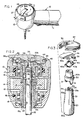
- Figure 1 is a perspective view of the head end portion of a dental handpiece embodying the chucking system of the present invention.
- Figure 2 is an enlarged vertical sectional view taken along line 2-2 of Figure 1.
- Figure 3 is an exploded perspective view of the major components of the chucking system.
- Figure 4 is a vertical sectional view similar to Figure 2 but showing the control lever in raised or extended position.
- Figure 5 is a greatly enlarged and somewhat exaggerated cross-sectional view taken along line 5-5 of Figure 2.
- Figure 6 is a longitudinal sectional view of the spring grip chuck in an untensioned state.
- Figure 7 is a vertical sectional view depicting another embodiment of the invention.
- Referring to the embodiment depicted in Figures 1 to 6, the
numeral 10 generally designates a handpiece having a handle 11 andhead 12. Within thechamber 13 of the head is arotor 14 adapted to be driven by air under pressure supplied through handle 11. The rotor is supported for rotation by upper andlower bearing assemblies resilient rings chamber 13 for purposes of reducing noise levels and attenuating vibrations during handpiece operation. -
Rotor 14 includes a bur tube orrotor tube 19, the bur tube having anaxial bore 19a and open upper andlower ends lower end 19c projects into an opening 12a at the lower end ofhandpiece head 12. - Within the lower portion of the
bore 19a of the bur tube is a tubularspring metal chuck 20. The chuck has an open-endedaxial bore 21 for receiving the cylindrical shank of adental bur 22. The bur is conventional, having a standard Type III shank as specified in ISO (International Organization for Standardization) standard 1797-1985(E). In accordance with that standard, such a shank should have a diameter within the range of .0626 to .0630 inches. - As shown most clearly in Figures 3 and 6, the spring grip chuck has a cylindrical
lower end portion 20a and a taperedupper end portion 20b. The upper end portion is longitudinally slotted at 23 to provide at least two upwardly-extending bur-grippingjaws 24. The optimum number of such jaws is believed to be two; however, a greater number may be provided if desired. Such jaws are in any case provided at their upper ends withinterior shoulder portions 25 having arcuate inner surfaces constituting segments of a bore of reduced diameter. Specifically, the opening defined by such surfaces at the time of chuck manufacture should have a diameter within the range of about .050 to .058 inches if the chuck is designed to receive standard burs of the .0626 to .0630 size race. The preferred diameter of the opening defined byinterior shoulder portions 25 is believed to be about .052 to .056 inches with particularly effective results being obtained with a diameter of .053 to .055 inches. - It is to be emphasized that the specified diameter for the opening defined by the opposing surfaces of
shoulder portions 25 is determined at the time of manufacture when the spring chuck is in an untensioned state. When the chuck is in use, with abur 22 gripped by thejaws 24, the jaws are flexed outwardly as depicted most clearly in Figure 2. Under such conditions, only thelower edges 25a ofshoulder portions 25 engage the cylindrical surface of the bur shank and, more specifically, only the corners or ends of such edged contact the bur shank because of the greater radius of curvature of the shank in relation to the radius of curvature of each of thelower edges 25a. Thus, as shown in Figure 5, edges 25a engage the shank at four circumferentially-spaced points of contact. Such a relationship assumes perfect concentricity between the bur shank and the chuck; if perfect concentricity is not attained, then such contact may occur at only three points (with an end or corner of one of theedges 25a being out of contact with the shank). It is also to be understood that if a greater number of jaws are provided, a correspondingly greater number of contact points will be made. - Chuck releasing means in the form of a generally cylindrical wedge-providing
element 30 is slidably received in theupper end 19b ofbur tube 19.Annular shoulders element 30 andbur tube 19, respectively, for limiting the extent of upward sliding movement of that element or member. At its lower end, the chuck releasing element or member is provided withwedge portions 31 that project intoslots 23 of thechuck 20. - To prevent free sliding movement of
element 30, the parts are preset during assembly so that thespring jaws 24 of the chuck are held in partially outwardly-flexed condition bywedge portions 31 even when the jaws are in their "closed" positions without a bur retained thereby. An important additional effect is that such jaws are already in a tensioned state prior to being opened for bur insertion or, stated differently, are preset to exert substantial clamping force on a bur having only slightly greater diameter than the diameter of the opening between the jaws when such jaws are closed without a bur clamped therebetween. Because the jaws of the chuck are pretensioned to exert substantial gripping force, and because further outward flexure increases both their tension and gripping force, such a chuck is highly effective in holding burs against rotational slippage during handpiece operation. - While such a construction does not appear to result in a relationship in which the bur pull-out forces are notably greater than, or even exceed, the pull-out forces for other spring grip chucks that are commercially available, the construction of this invention is particularly resistant to bur slippage (relative rotation between bur and chuck) during cutting operations. Such results are attained without hardening or special treatment of the tips of
jaws 24. The preset condition is achieved by first inserting the wedge element ormember 30 into its fully raised position within thebore 19a ofbur tube 19, then insertingchuck 20 until its jaws engagewedge portions 31 and flex outwardly to a limited extent, and finally permanently securing the chuck in position byweld 32 at the lower ends of the chuck and bur tube (Figure 2). - The pretensioning of the jaws should be substantial enough so that the difference in jaw spacing when in untensioned condition (before presetting) and when engaging a bur of minimum diameter (.0626 inches) is about .005 to .013 inches, preferably about .007 to .011 inches. It should be understood that the optimum differential depends in part on the physical charteristics of the spring material selected for the chuck. While any of a variety of spring metals may be used, particularly effective results have been achieved using a high-strength stainless spring steel having the following mechanical properties at room temperature when tested as a one-inch bar section: a 0.2% yield strength of 225,000 psi; an elongation of 12% (in 4D); and a hardness of 48 on the Rockwell C scale. Such a steel is commercially available under the designation "custom 455" from Carpenter Technology corporation, Redding, Pennsylvania, and other steels having similar properties may be available elsewhere.
- The wedge-providing element or
member 30 has anaxial bore 33 aligned with thebore 21 ofchuck 20. Likebore 21, bore 33 is only slightly larger in diameter than the outside diameter ofbur 22. A differential of about .0002 to .0013 inches has been found suitable; therefore, where a handpiece designed for use with standard burs of a diameter within the range of .0626 to .0630 inches, the diameter ofbores - As shown in Figure 2, the upper end of the wedge-providing
member 30 projects upwardly from the openupper end 19b ofbur tube 19 and provides an upwardly-facingbearing surface 35 disposed directly below acontrol lever 36 pivotally carried by disk-shaped cap or covermember 37. The lever includes ahandle portion 36a, acam portion 36b, and atransverse pivot shaft 38. In the preferred embodiment shown, thepivot shaft 38 has its horizontal axis substantially perpendicular to the vertical longitudinal axis of the bur tube and the chucking mechanism retained by it. It will be observed thatlever portion 36a is considerably longer thancam portion 36b -- preferably at least three times greater in length -- so that a substantial mechanical advantage is produced when the lever is pivoted upwardly from its horizontal retracted position (Figure 2) into its raised or extended position (Figure 4). - When lowered, the
control lever 36 is received and substantially concealed within a recess orslot 39 formed in the disk-shapedcover 37. The end of the handle portions of the retracted lever protrudes a slight distance radially outwardly beyond the outer surface of the handpiece's head although its radial extent does not exceed the full radius of that head (Figure 2). The protrusion of the handle portion provides an undercut for catching the lever with a fingernail and commencing upward pivotal movement of the lever into the fully raised or extended position of Figure 4. - Ideally, the lever is mounted so that its undersurface is spaced above bearing
surface 35 ofwedge member 30 when the lever is in its lowered or retracted position (Figure 2). Such a relationship facilitates commencement of upward pivotal movement of the lever when chuck actuation is desired (because the first few degrees of pivotal movement do not involve contact withwedge member 30 and application of the substantial forces necessary to drive the wedge member downwardly to open the jaws of chuck 20) and also performs a protective function (since there is no risk that limited upward pivotal movement of the lever will cause bur release). A leaf spring 40 of developed shape is disposed beneathcover 37 and exerts an upward force againstcam portion 36b of the lever to hold the lever in its lowered or retracted position. As shown most clearly in Figure 3, the spring includes an arcuateupper portion 40a that bears against the cam surface of the lever, anannular portion 40b that extends about the protruding upper end ofwedge member 30, and a hook portion 40c that extends upwardly and is received within theslot 39 in which the control lever is mounted. Spring 40 therefore exerts a force sufficient to hold the control lever in its lowered or retracted position until such time as the operator wishes to insert or remove abur 22. - The disk-shaped
cover 37 is mounted for rotation within upwardly-facingcavity 42 provided byhead 12. A retainingring 43 is received within opposinggrooves cover slot 39, the spring rotates along with the cover into whatever position is selected by the operator. A dentist's operating technique may make it desirable for thecover 37 andcontrol lever 36 to be oriented in the positions depicted in Figure 1; if another angular position of the lever would be more suitable, the dentist may rotate the cover one way or the other, as represented byarrows 46, into any desired position over a sweep of 360°. - To release the
chuck 20, an operator simply pivotslever 36 into the raised position depicted in Figure 4. As thehandle portion 36a is raised, thecam portion 36b drives thewedge member 30 downwardly so thatwedge portions 31 are expanded outwardly to permit insertion or removal of abur 22. It is to be noted that when the control lever is fully raised, the substantial inwardly-directed forces exerted by thejaws 24 of the chuck generate a reactive force that tends to hold the lever in its raised position. More specifically, thejaws 24 exert a reactive camming force againstwedge member 30 causing itssurface 35 to bear upwardly against the arcuate surface ofcam portion 36b of the lever and, since the lever has been pivoted more than 90° (i.e., beyond vertical), the control lever will tend to remain in the raised position of Figure 4 unless it is intentionally pivoted downwardly into its lowered position of Figure 2. Furthermore, during such downward pivotal movement, the spring force exerted by thejaws 24, and also the upward force exerted by leaf spring 40, urge the lever into its lowered position after it has passed a vertical mid point in its path of pivotal movement. - The
handpiece 10′ illustrated in Figure 7 is basically similar to the one already described; however, it incorporates astator 50 withorifices 51 for directing drive air downwardly in a general axial direction against the vanes ofrotor 14′. Such a construction results in a handpiece having a relatively long bur orrotor tube 19′. The proportions ofspring grip chuck 20′ are similar to those of the previously-described chuck but a comparison of the drawings will reveal that wedge-providingmember 30′ is considerably longer for its diameter than wedge-providingmember 30. - Unlike
wedge member 30,wedge member 30′ is composed of upper andlower sections bore 54 with a diameter only slightly greater than the diameter of a bur to be received therein, thebore 55 of thelower section 53 is shown to be substantially larger than either bore 54 of the upper section or bore 21′ ofchuck 20′. This permits slight displacement or tipping action of thelower section 53, without affecting the concentricity ofbores bore 54, when thejaws 24′ of the chuck have been forced into their opened positions by upward pivotal movement ofcam lever 36′ and resulting downward movement ofwedge member 30′. Stated differently, the spacing between the inner surface ofbore 54 and the outer surface of a bur may be kept to a minimum without risk that thewedge portions 31′ of the two-section member 30′ might be forced out of alignment withbore 21′ when the jaws of thechuck 20′ are forced open. Should slight tipping action oflower section 53 occur under such circumstances, the relatively large inside diameter ofbore 55 will still accommodate the bur, and theupper section 52 with its bur-pilotingbore 54 will remain unaffected. - Also, unlike
spring grip chuck 20, chuck 20′ has lower andupper sections 20a′ and 20b′ that consist of separate pieces locked together against independent relative rotation by means of interfitting tongue 60 and recess 61. The bore 21a′ of thelower section 20a′ has a diameter only slightly greater than the outside diameter of a bur and therefore performs the piloting function indicated above. The lower section 21a′ is secured byweld 32′ tobur tube 19′ and presets the tension of thejaws 24′ in the same manner already described. However, because the chuck is formed in two sections, the piloting and gripping functions are divided with the piloting function being performed by thelower section 20a′ and the gripping function being performed by theupper section 20b′. For that reason, bore 21b′ of the upper section may be substantially larger than the bore 21a′ of the lower section (as shown). Such a construction assures that the outward flexing of the pretensioned jaws into their fully open positions will not be accompanied by cross-sectional deformations of thelower section 20a′ that might tend to reduce its piloting effectivness. - While a two-piece chuck has been shown only in connection with the second embodiment of Figure 7, it is believed apparent that such a construction may also be utilized with the embodiment of Figures 1-6. Conversely, the construction of Figure 7 might, if desired, be provided with a one-piece chuck of the type shown and described in connection with the first embodiment.
- While in the foregoing, embodiments of the invention have been disclosed in considerable detail for purposes of of illustration, it will be understood by those skilled in the art that many of such details may be varied without departing from the spirit and scope of the invention.
Claims (15)
Applications Claiming Priority (2)
| Application Number | Priority Date | Filing Date | Title |
|---|---|---|---|
| US36156989A | 1989-06-05 | 1989-06-05 | |
| US361569 | 1989-06-05 |
Publications (2)
| Publication Number | Publication Date |
|---|---|
| EP0401987A2 true EP0401987A2 (en) | 1990-12-12 |
| EP0401987A3 EP0401987A3 (en) | 1991-03-20 |
Family
ID=23422563
Family Applications (1)
| Application Number | Title | Priority Date | Filing Date |
|---|---|---|---|
| EP19900305284 Ceased EP0401987A3 (en) | 1989-06-05 | 1990-05-16 | Dental handpiece |
Country Status (4)
| Country | Link |
|---|---|
| EP (1) | EP0401987A3 (en) |
| JP (1) | JP3228734B2 (en) |
| CA (1) | CA2016023C (en) |
| NO (1) | NO902456L (en) |
Cited By (3)
| Publication number | Priority date | Publication date | Assignee | Title |
|---|---|---|---|---|
| DE19945322A1 (en) * | 1999-09-22 | 2001-05-03 | Aesculap Ag & Co Kg | Chuck for surgical drill has jaw which can slide longitudinally in chuck, is locked in position by sleeve to hold drill bit and is biased towards locking position by leaf spring |
| CN107041787A (en) * | 2016-12-30 | 2017-08-15 | 宁波和平鸽口腔医疗器材有限公司 | Air impeller mobile phone clamps axle |
| WO2024052004A1 (en) * | 2022-09-08 | 2024-03-14 | Neolix | Tool-holder device for an endodontic instrument |
Families Citing this family (2)
| Publication number | Priority date | Publication date | Assignee | Title |
|---|---|---|---|---|
| EP1733696B1 (en) * | 2005-06-15 | 2008-04-16 | Bien-Air Holding SA | Handpiece for dental or surgical use with an elastic collet |
| US20130029288A1 (en) * | 2011-07-29 | 2013-01-31 | Dentsply International, Inc. | Positive drive chuck and bur arrangement for a dental handpiece |
Citations (5)
| Publication number | Priority date | Publication date | Assignee | Title |
|---|---|---|---|---|
| US4089115A (en) * | 1976-11-17 | 1978-05-16 | American Hospital Supply Corporation | Spring grip chuck assembly for dental handpieces |
| EP0037021A1 (en) * | 1980-03-28 | 1981-10-07 | Siemens Aktiengesellschaft | Holding device for a rotatable dental tool |
| FR2555042A1 (en) * | 1983-11-23 | 1985-05-24 | Micro Mega Sa | Thruster with cam |
| DE3402635A1 (en) * | 1984-01-26 | 1985-08-08 | Kaltenbach & Voigt Gmbh & Co, 7950 Biberach | Clamping device for the clamping of tools |
| US4874314A (en) * | 1986-12-22 | 1989-10-17 | Siemens Aktiengesellschaft | Socket to clampingly hold dental tools |
-
1990
- 1990-05-03 CA CA002016023A patent/CA2016023C/en not_active Expired - Lifetime
- 1990-05-16 EP EP19900305284 patent/EP0401987A3/en not_active Ceased
- 1990-06-01 NO NO90902456A patent/NO902456L/en unknown
- 1990-06-05 JP JP14556490A patent/JP3228734B2/en not_active Expired - Lifetime
Patent Citations (5)
| Publication number | Priority date | Publication date | Assignee | Title |
|---|---|---|---|---|
| US4089115A (en) * | 1976-11-17 | 1978-05-16 | American Hospital Supply Corporation | Spring grip chuck assembly for dental handpieces |
| EP0037021A1 (en) * | 1980-03-28 | 1981-10-07 | Siemens Aktiengesellschaft | Holding device for a rotatable dental tool |
| FR2555042A1 (en) * | 1983-11-23 | 1985-05-24 | Micro Mega Sa | Thruster with cam |
| DE3402635A1 (en) * | 1984-01-26 | 1985-08-08 | Kaltenbach & Voigt Gmbh & Co, 7950 Biberach | Clamping device for the clamping of tools |
| US4874314A (en) * | 1986-12-22 | 1989-10-17 | Siemens Aktiengesellschaft | Socket to clampingly hold dental tools |
Cited By (7)
| Publication number | Priority date | Publication date | Assignee | Title |
|---|---|---|---|---|
| DE19945322A1 (en) * | 1999-09-22 | 2001-05-03 | Aesculap Ag & Co Kg | Chuck for surgical drill has jaw which can slide longitudinally in chuck, is locked in position by sleeve to hold drill bit and is biased towards locking position by leaf spring |
| DE19945322B4 (en) * | 1999-09-22 | 2004-02-12 | Aesculap Ag & Co. Kg | chuck |
| DE19945322B8 (en) * | 1999-09-22 | 2004-07-08 | Aesculap Ag & Co. Kg | chuck |
| CN107041787A (en) * | 2016-12-30 | 2017-08-15 | 宁波和平鸽口腔医疗器材有限公司 | Air impeller mobile phone clamps axle |
| CN107041787B (en) * | 2016-12-30 | 2022-09-13 | 宁波和平鸽口腔医疗器材有限公司 | Pneumatic turbine cell-phone centre gripping axle |
| WO2024052004A1 (en) * | 2022-09-08 | 2024-03-14 | Neolix | Tool-holder device for an endodontic instrument |
| FR3139459A1 (en) * | 2022-09-08 | 2024-03-15 | Neolix | Instrument holder equipment for endodontic instrument |
Also Published As
| Publication number | Publication date |
|---|---|
| NO902456D0 (en) | 1990-06-01 |
| NO902456L (en) | 1990-12-06 |
| CA2016023C (en) | 2002-12-24 |
| CA2016023A1 (en) | 1990-12-05 |
| JP3228734B2 (en) | 2001-11-12 |
| JPH0323855A (en) | 1991-01-31 |
| EP0401987A3 (en) | 1991-03-20 |
Similar Documents
| Publication | Publication Date | Title |
|---|---|---|
| US5040980A (en) | Dental handpiece with spring grip chuck and lever release mechanism | |
| JP4969921B2 (en) | Dental or medical handpiece with flexible clamp | |
| US7448870B2 (en) | Handpiece for dental or surgical use with locking mechanism | |
| US4140161A (en) | Screw holding and driving device | |
| USRE37358E1 (en) | Tool holding mechanism for a motor driven surgical instrument | |
| JP4928574B2 (en) | Surgical handpiece | |
| CA1149648A (en) | Chuck assembly for dental handpieces | |
| US5591028A (en) | Dental cutting tool holder | |
| US4536157A (en) | Lever actuated chuck mechanism for dental handpiece | |
| US20060281048A1 (en) | Adjustable tool drive arrangement | |
| US6135462A (en) | Snap-in chuck | |
| US4199160A (en) | Surgical drill chuck | |
| US7563061B2 (en) | Self-centering drill bit chuck | |
| US6190168B1 (en) | Dental handpiece having improved bur release means | |
| US4811736A (en) | Surgical drill and bur for use therewith | |
| US20020105149A1 (en) | Centrifugal dental drill bit chuck | |
| US5354075A (en) | Keyless drill chuck | |
| US6179615B1 (en) | Dental drill with integral guide | |
| EP0401987A2 (en) | Dental handpiece | |
| CN109788998B (en) | Dental treatment instrument for operating a rotary cutter | |
| EP1519690B1 (en) | Coated dental handpiece | |
| US20070031786A1 (en) | Dental handpiece | |
| WO2001052764A1 (en) | Retention quill for a chucking system in a dental handpiece | |
| EP1232731B1 (en) | Dental handpiece having improved bur release means | |
| JP3126887B2 (en) | Chuck mechanism |
Legal Events
| Date | Code | Title | Description |
|---|---|---|---|
| PUAI | Public reference made under article 153(3) epc to a published international application that has entered the european phase |
Free format text: ORIGINAL CODE: 0009012 |
|
| AK | Designated contracting states |
Kind code of ref document: A2 Designated state(s): AT DE DK ES FR GB IT SE |
|
| PUAL | Search report despatched |
Free format text: ORIGINAL CODE: 0009013 |
|
| AK | Designated contracting states |
Kind code of ref document: A3 Designated state(s): AT DE DK ES FR GB IT SE |
|
| 17P | Request for examination filed |
Effective date: 19910409 |
|
| 17Q | First examination report despatched |
Effective date: 19920707 |
|
| STAA | Information on the status of an ep patent application or granted ep patent |
Free format text: STATUS: THE APPLICATION HAS BEEN REFUSED |
|
| 18R | Application refused |
Effective date: 19960427 |