EP0401943A2 - Heat dilatation compensation device - Google Patents
Heat dilatation compensation device Download PDFInfo
- Publication number
- EP0401943A2 EP0401943A2 EP90250115A EP90250115A EP0401943A2 EP 0401943 A2 EP0401943 A2 EP 0401943A2 EP 90250115 A EP90250115 A EP 90250115A EP 90250115 A EP90250115 A EP 90250115A EP 0401943 A2 EP0401943 A2 EP 0401943A2
- Authority
- EP
- European Patent Office
- Prior art keywords
- sleeve
- thermal expansion
- fastening
- motion picture
- intermediate sleeve
- Prior art date
- Legal status (The legal status is an assumption and is not a legal conclusion. Google has not performed a legal analysis and makes no representation as to the accuracy of the status listed.)
- Granted
Links
Images


Classifications
-
- G—PHYSICS
- G03—PHOTOGRAPHY; CINEMATOGRAPHY; ANALOGOUS TECHNIQUES USING WAVES OTHER THAN OPTICAL WAVES; ELECTROGRAPHY; HOLOGRAPHY
- G03B—APPARATUS OR ARRANGEMENTS FOR TAKING PHOTOGRAPHS OR FOR PROJECTING OR VIEWING THEM; APPARATUS OR ARRANGEMENTS EMPLOYING ANALOGOUS TECHNIQUES USING WAVES OTHER THAN OPTICAL WAVES; ACCESSORIES THEREFOR
- G03B17/00—Details of cameras or camera bodies; Accessories therefor
- G03B17/02—Bodies
- G03B17/10—Soundproof bodies
-
- G—PHYSICS
- G03—PHOTOGRAPHY; CINEMATOGRAPHY; ANALOGOUS TECHNIQUES USING WAVES OTHER THAN OPTICAL WAVES; ELECTROGRAPHY; HOLOGRAPHY
- G03B—APPARATUS OR ARRANGEMENTS FOR TAKING PHOTOGRAPHS OR FOR PROJECTING OR VIEWING THEM; APPARATUS OR ARRANGEMENTS EMPLOYING ANALOGOUS TECHNIQUES USING WAVES OTHER THAN OPTICAL WAVES; ACCESSORIES THEREFOR
- G03B17/00—Details of cameras or camera bodies; Accessories therefor
- G03B17/55—Details of cameras or camera bodies; Accessories therefor with provision for heating or cooling, e.g. in aircraft
Definitions
- the invention relates to a device for connecting two components of a motion picture camera, in particular for connecting a lens carrier to the camera body or a film guide to the film transport device.
- a film recording camera with a housing in which a camera work is included, which moves the film through a film guide past a picture window and intermittently interrupts and releases the light thrown into the picture window by a lens.
- a structure-borne sound-absorbing, but dimensionally stable connection is interposed between the camera work and a lens receiving part and a structure-borne sound-insulating housing closure is inserted between the lens receiving part and the housing.
- the housing closure Due to the special design of the housing closure in such a way that it carries the lens receiving part and thus also the parts connected to it, namely the lens and the camera work on the housing under its own power, a minimal noise level is achieved without the required exact location assignment between the lens and Film level is affected.
- motion picture cameras require the highest precision in the manufacture and assembly of the film guide elements, for example with regard to the surface and position of the gripper tips in relation to the film guide. Since there is a gap between the film guide and the gripper tips in which the motion picture film is moved, it is also necessary that this gap is absolutely constant for exact maintenance of the image plane and an optimal assignment between the film perforation and the gripper tips, which is also the case when using the Motion picture camera leads to problems with extreme temperature differences.
- the object of the present invention is therefore to create a device for connecting two components of a motion picture camera, which ensures a high dimensional stability of the connection even in the case of extreme temperature differences.
- the solution according to the invention ensures that various components of a motion picture camera even at extreme temperatures Differences in temperature have a high dimensional accuracy of their connection, whereby extreme differences in the thermal expansion coefficients of the different component materials can be compensated. This ensures that sound-absorbing materials can be used to avoid or reduce noise and at the same time ensure a constant connection dimension of the various components.
- the first element consists of a fastening pin which is connected to the one component in a non-positive and / or form-fitting manner
- the second element consists of a fastening sleeve which is connected to the second component in a non-positive and / or positive manner
- the intermediate element there is an intermediate sleeve connected radially to the fastening pin and the fastening sleeve, an axial gap being provided between the end faces of the intermediate sleeve and the components to be connected to one another.
- This configuration of the thermal expansion compensating pendulum ensures a minimum size with maximum compensating properties, so that the shape of the thermal expansion compensating pendulum is particularly suitable for use in precision mechanical devices such as a motion picture camera, without requiring a larger space.
- a further advantageous development of the solution according to the invention is characterized in that a radial gap between the inner surface of the fastening sleeve and the outer surface of the intermediate sleeve is provided over a wide range of the two contact surfaces.
- the intermediate sleeve may have on one end face a shoulder which projects radially beyond the outer surface of the intermediate sleeve, the surface of which facing away from the end face of the intermediate sleeve bears against one end face of the fastening sleeve, and that a small part of the outer surface of the intermediate sleeve corresponds to a corresponding part of the inner surface of the Fastening sleeve is non-positively and / or positively connected.
- a further advantageous development of the solution according to the invention is characterized in that the components of the motion picture camera to be connected to one another are connected to extension elements, between whose ends arranged in a free position in the motion picture camera a heat expansion compensation pendulum is arranged.
- fastening pin and the fastening sleeve made of PERNIFER with a thermal expansion coefficient of 1.2 x 10 ⁇ 6 mm / ° C and the intermediate sleeve made of an aluminum-tin-magnesium-copper alloy with a thermal expansion coefficient of 23 x 10 ⁇ 6 mm / ° C exist.
- the longitudinal section shown in Figure 1 through the front part of a motion picture camera 1 shows a profile piece 17 arranged in a housing 13 of the motion picture camera 1 and made of a plastic or rubber-like material, which is provided for reducing noise when connecting the lens-internal camera and the transmission of structure-borne noise from the inner camera on the lens is reduced to a minimum by appropriate noise insulation measures.
- the profile piece 17 is fastened by means of screws which pull a metal plate vulcanized or glued to the profile piece against a front surface of the housing 13 of the motion picture camera 1.
- a metal plate is also vulcanized or glued, which in turn is connected to the lens carrier 11.
- An exchangeable lens 2 is accommodated in the lens carrier 11 in a known manner.
- the film guide plane 15 is formed by a film gap S, in which the motion picture film is guided and is intermittently transported through a film switching mechanism 16 by means of gripper tips which engage in the film perforation.
- the film becomes a film box via pre and post winding rolls sette transported, which can be attached to the housing 13 of the motion picture camera 1.
- a rotating mirror diaphragm 14 serves to expose the film or to cover the film during the film transport phase.
- the profile piece 17 is provided , which reduces the transmission of structure-borne noise from the area of the inner camera 10 to the lens carrier 11 and thus to the lens 2 to a minimum.
- a thermal expansion compensation pendulum 3 a so-called Rost pendulum, is used in the motion picture camera 1 shown in FIG. 1, in the connection between the lens carrier 11 and the inner camera or camera body 10 .
- thermal expansion compensating pendulum 3 The arrangement of the thermal expansion compensating pendulum 3 is shown only schematically in FIG. 1.
- a thermal expansion compensation pendulum can be used to connect the film switching mechanism 16 to the film guide level 15, so that the film gap S remains constant in the temperature range of the motion picture camera 1 at any temperature between -20 ° C and + 50 ° C, so that evasive movements of the Films from the film level are avoided and an exact engagement of the gripper tips in the film perforation is ensured to avoid unnecessary noise.
- FIG. 2 shows a front view of the motion picture camera 1 with the lens carrier 11 and the lens bore 12.
- thermal expansion compensation pendulums 3, 3 * are installed in the lens carrier 11 in the region of the lens axis to the right and left of the lens bore 12. The more precise structure of the thermal expansion compensating pendulums 3, 3 * is explained in more detail below with reference to FIGS. 3 to 5.
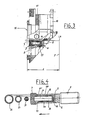
- FIG. 3 shows a longitudinal section through the camera body 10 in the region of the lens carrier 11.
- This longitudinal section shows the connection of the lens carrier 11 to the camera body 10 via one or optionally a plurality of profile pieces 17 made of a rubber-like material to minimize the transmission of structure-borne noise from the film switching mechanism connected to the camera body 10 to the lens 2 to be connected to the lens carrier 11, the axis of which is denoted by LA is.
- a thermal expansion compensation pendulum 3 is provided, which on the one hand has a first plug 7 with the lens carrier 11 and on the other hand has a connecting plate 5, a plexiglass plate 6 and a threaded plug 8 is connected to the camera body 10.
- thermal expansion compensating pendulum 3 connected to the camera body 10 is inserted into a profile piece 17 to minimize noise transmission, so that no or only a minimal sound bridge is created by the thermal expansion compensating pendulum 3.
- the detailed structure of the thermal expansion compensating pendulum 3 will be explained in more detail below with reference to FIGS. 4 and 5.
- FIG. 4 shows a detailed representation of the thermal expansion compensating pendulum in longitudinal section and schematically in cross section and the connection of the thermal expansion compensating pendulum 3 with a plug 7 connected to the lens carrier 11 on the one hand and with a mounting plate 5, a plexiglass connecting element 6 and a threaded plug 8 on the other which are connected to the camera body 10 according to FIG. 3.
- the thermal expansion compensating pendulum consists of a fastening pin 31, which in this exemplary embodiment is non-positively connected to the plug 7, the end face of the fastening pin 31 resting firmly on the bottom of the plug 7.
- the intermediate sleeve 33 is U-shaped in longitudinal section with a radial shoulder 331 formed on one end face, the outer diameter of the U-shaped part 330 of the intermediate sleeve 33 being dimensioned in relation to a large part of the inner diameter of the fastening sleeve 32 such that a radial gap 44 is formed. Only in the area of the shoulder 331 is there a non-positive connection between the outer surface of the intermediate sleeve 33 and the inner surface of the fastening sleeve 33.
- intermediate sleeve 33 is axially spaced from the stopper 7 on the one hand and the fastening plate 5 on the other hand such that a small axial gap 41, 42 is formed in each case.
- the end face of the fastening pin 31 opposite the stopper 7 also lies firmly against the bottom of the U-shaped body 330 of the intermediate sleeve 33 and forms a fixed contact surface with the latter.
- the material of the fastening pin 31 and the fastening sleeve 32 consists of PERNIFER 36 with a heat exchanger expansion coefficient of 1.2 x 10 ⁇ 6 mm / ° C, while the material of the intermediate sleeve 33 made of an aluminum-tin-magnesium-copper alloy (AlZnMgCu 1.5 F52) with a coefficient of thermal expansion of 23 x 10 ⁇ 6 mm / ° C.
- FIG. 5 illustrates in an enlargement of section X according to FIG. 4 the connection of the individual elements 31, 32, 33 of the thermal expansion compensation pendulum 3 to form an axial gap 42, which is required for the thermal expansion compensation.
- the non-positive connection shown in Figures 4 and 5 of the individual elements 31, 32, 33 of the thermal expansion compensating pendulum 3 and their connection to the mounting parts 5, 7 of the components 10, 11 of the motion picture camera can also by a positive connection and a combined positive and non-positive connection to be replaced.
Abstract
Description
Die Erfindung betrifft eine Vorrichtung zum Verbinden von zwei Bauteilen einer Laufbildkamera, insbesondere zum Verbinden eines Objektivträgers mit dem Kamerakörper bzw. einer Filmführung mit der Filmtransporteinrichtung.The invention relates to a device for connecting two components of a motion picture camera, in particular for connecting a lens carrier to the camera body or a film guide to the film transport device.
Bei optischen Geräten allgemein und bei Laufbildkameras im besonderen ist äußerste Maßhaltigkeit der einzelnen Bauteile des optischen Geräts von größter Bedeutung. Eine exakte Maßhaltigkeit sorgt bei Laufbildkameras für eine genaue Abbildung des aufzunehmenden Objekts auf die Bildebene sowie für eine exakte Filmführung, wodurch seitliche Ausweichbewegungen des Films sowie Ausweichbewegungen senkrecht zur Filmfläche und damit unscharfe Bilder sowie unnötige Geräuschentwicklungen vermieden werden.With optical devices in general and with motion picture cameras in particular, extreme dimensional accuracy of the individual components of the optical device is of the utmost importance. With motion picture cameras, exact dimensional accuracy ensures that the object to be photographed is precisely depicted on the image plane and that film is guided exactly, avoiding lateral evasive movements of the film and evasive movements perpendicular to the film surface, thus avoiding blurred images and unnecessary noise.
Aus der DE-PS 35 38 827 ist eine Filmaufnahmekamera mit einem Gehäuse bekannt, in dem ein Kamerawerk eingeschlossen ist, das den Film über eine Filmführung an einem Bildfenster absatzweise vorbeibewegt und das durch ein Objektiv ins Bildfenster geworfene Licht abwechselnd unterbricht und freigibt. Zur Reduzierung der Geräuscherzeugung ist zwischen dem Kamerawerk und einem Objektivaufnahmeteil eine körperschallabsorbierende, jedoch maßhaltige Verbindung zwischengeschaltet und zwischen dem Objektivaufnahmeteil und dem Gehäuse ein körperschallisolierender Gehäuseabschluß eingefügt.From DE-PS 35 38 827 a film recording camera with a housing is known, in which a camera work is included, which moves the film through a film guide past a picture window and intermittently interrupts and releases the light thrown into the picture window by a lens. To reduce the generation of noise, a structure-borne sound-absorbing, but dimensionally stable connection is interposed between the camera work and a lens receiving part and a structure-borne sound-insulating housing closure is inserted between the lens receiving part and the housing.
Durch spezielle Ausgestaltung des Gehäuseabschlusses in der Weise, daß er das Objektivaufnahmeteil und damit auch die an dieses angeschlossene Teile, nämlich das Objektiv und das Kamerawerk aus eigener Kraft am Gehäuse trägt, wird ein minimaler Geräuschpegel erzielt, ohne daß die geforderte exakte Lagezuordnung zwischen Objektiv und Filmebene beeinträchtigt wird.Due to the special design of the housing closure in such a way that it carries the lens receiving part and thus also the parts connected to it, namely the lens and the camera work on the housing under its own power, a minimal noise level is achieved without the required exact location assignment between the lens and Film level is affected.
Bei den Maßnahmen zur Minimierung bei der Übertragung des Körperschalls von der Innenkamera auf das Objektiv werden notwendigerweise jedoch Materialien unterschiedlichster Art verwendet, was die Gefahr einschließt, daß bei einem Einsatz der Laufbildkamera in extremen Temperaturbereichen von bsp. +50 °C bis -20 °C das Auflagemaß, d.h. die Distanz zwischen dem Objektivträger und der Filmebene sich verändert, so daß die Gefahr der Aufnahme unscharfer Bilder besteht.When taking measures to minimize the transmission of structure-borne noise from the indoor camera to the lens However, materials of all kinds are necessarily used, which includes the risk that when the motion picture camera is used in extreme temperature ranges of e.g. +50 ° C to -20 ° C the back focus, ie the distance between the lens holder and the film plane changes, so that there is a risk of taking blurred images.
Zur Geräuschvermeidung ist bei Laufbildkameras höchste Präzision bei der Fertigung und Montage der Filmführungselemente erforderlich, bspw. bezüglich der Oberfläche und Lage der Greiferspitzen in Bezug auf die Filmführung. Da zwischen der Filmführung und den Greiferspitzen ein Spalt besteht, in dem der Laufbildfilm bewegt wird, ist es ebenfalls erforderlich, daß dieser Spalt zur exakten Einhaltung der Bildebene und einer optimalen Zuordnung zwischen der Filmperforation und den Greiferspitzen absolut konstant ist, was ebenfalls beim Einsatz der Laufbildkamera bei extremen Temperaturunterschieden zu Problemen führt.In order to avoid noise, motion picture cameras require the highest precision in the manufacture and assembly of the film guide elements, for example with regard to the surface and position of the gripper tips in relation to the film guide. Since there is a gap between the film guide and the gripper tips in which the motion picture film is moved, it is also necessary that this gap is absolutely constant for exact maintenance of the image plane and an optimal assignment between the film perforation and the gripper tips, which is also the case when using the Motion picture camera leads to problems with extreme temperature differences.
Aufgabe der vorliegenden Erfindung ist es daher, eine Vorrichtung zur Verbindung zweier Bauteile einer Laufbildkamera zu schaffen, die eine hohe Maßhaltigkeit der Verbindung auch bei extremen Temperaturunterschieden gewährleistet.The object of the present invention is therefore to create a device for connecting two components of a motion picture camera, which ensures a high dimensional stability of the connection even in the case of extreme temperature differences.
Diese Aufgabe wir durch das kennzeichnende Merkmal des Anspruchs 1 gelöst.This object is achieved by the characterizing feature of claim 1.
Die erfindungsgemäße Lösung stellt sicher, daß verschiedene Bauteile einer Laufbildkamera auch bei extremen Tempe raturunterschieden eine hohe Maßhaltigkeit ihrer Verbindung aufweisen, wobei extreme Unterschiede der Wärmeausdehnungskoeffizienten der verschiedenen Bauteilmaterialien ausgeglichen werden können. Dadurch wird gewährleistet, daß schallabsorbierende Materialien zur Geräuschvermeidung oder Geräuschreduzierung eingesetzt werden können und gleichzeitig ein konstantes Verbindungsmaß der verschiedenen Bauteile sichergestellt ist.The solution according to the invention ensures that various components of a motion picture camera even at extreme temperatures Differences in temperature have a high dimensional accuracy of their connection, whereby extreme differences in the thermal expansion coefficients of the different component materials can be compensated. This ensures that sound-absorbing materials can be used to avoid or reduce noise and at the same time ensure a constant connection dimension of the various components.
Eine vorteilhafte Weiterbildung der erfindungsgemäßen Lösung ist dadurch gekennzeichnet, daß das erste Element aus einem mit dem einen Bauteil kraft- und/oder formschlüssig verbundenen Befestigungsstift, das zweite Element aus einer mit dem zweiten Bauteil kraft- und/oder formschlüssig verbundenen Befestigungshülse und das Zwischenelement aus einer radial mit dem Befestigungsstift und der Befestigungshülse verbundenen Zwischenhülse besteht, wobei zwischen den Stirnflächen der Zwischenhülse und den miteinander zu verbindenden Bauteilen ein axialer Spalt vorgesehen ist.An advantageous development of the solution according to the invention is characterized in that the first element consists of a fastening pin which is connected to the one component in a non-positive and / or form-fitting manner, the second element consists of a fastening sleeve which is connected to the second component in a non-positive and / or positive manner, and the intermediate element there is an intermediate sleeve connected radially to the fastening pin and the fastening sleeve, an axial gap being provided between the end faces of the intermediate sleeve and the components to be connected to one another.
Diese Ausgestaltung des Wärmedehnungs-Ausgleichspendels gewährleistet eine minimale Baugröße bei maximalen Ausgleichseigenschaften, so daß sich die Form des Wärmedehnungs-Ausgleichspendels insbesondere zum Einsatz in feinmechanischen Geräten wie einer Laufbildkamera eignet, ohne daß ein größerer Platzbedarf besteht.This configuration of the thermal expansion compensating pendulum ensures a minimum size with maximum compensating properties, so that the shape of the thermal expansion compensating pendulum is particularly suitable for use in precision mechanical devices such as a motion picture camera, without requiring a larger space.
Eine weitere vorteilhafte Weiterbildung der erfindungsgemäßen Lösung ist dadurch gekennzeichnet, daß ein radialer Spalt zwischen der Innenfläche der Befestigungshülse und der Außenfläche der Zwischenhülse über einen weiten Bereich der beiden Berührungsflächen vorgesehen ist. Zusätzlich kann die Zwischenhülse an ihrer einen Stirnseite eine radial über die Außenfläche der Zwischenhülse ragende Schulter aufweisen, deren der Stirnseite der Zwischenhülse abgewandte Fläche an der einen Stirnseite der Befestigungshülse anliegt, und daß ein geringer Teil der Außenfläche der Zwischenhülse mit einem entsprechenden Teil der Innenfläche der Befestigungshülse kraft- und/oder formschlüssig verbunden ist.A further advantageous development of the solution according to the invention is characterized in that a radial gap between the inner surface of the fastening sleeve and the outer surface of the intermediate sleeve is provided over a wide range of the two contact surfaces. In addition, the intermediate sleeve may have on one end face a shoulder which projects radially beyond the outer surface of the intermediate sleeve, the surface of which facing away from the end face of the intermediate sleeve bears against one end face of the fastening sleeve, and that a small part of the outer surface of the intermediate sleeve corresponds to a corresponding part of the inner surface of the Fastening sleeve is non-positively and / or positively connected.
Eine weitere vorteilhafte Weiterbildung der erfindungsgemäßen Lösung ist dadurch gekennzeichnet, daß die miteinander zu verbindenden Bauteile der Laufbildkamera mit Verlängerungselementen verbunden sind, zwischen deren an einer freien Stelle in der Laufbildkamera angeordneten Enden ein Wärmedehnungs-Ausgleichspendel angeordnet ist.A further advantageous development of the solution according to the invention is characterized in that the components of the motion picture camera to be connected to one another are connected to extension elements, between whose ends arranged in a free position in the motion picture camera a heat expansion compensation pendulum is arranged.
Diese Weiterbildung der erfindungsgemäßen Lösung ermöglicht es, auch solche Bauteile einer Laufbildkamera miteinander maßhalig über ein Wärmedehnung-Ausgleichspendel miteinander zu verbinden, deren Anordnung und/oder Lage den Einsatz eines solchen Wärmedehnungs-Ausgleichspendels normalerweise verbietet. Erfolgt die Verbindung dieser Bauteile jedoch über Verlängerungselemente an einer Stelle, wo ausreichend Platz zur Anordnung eines Wärmedehnungs-Ausgleichspendels besteht, so kann die exakte Zuordnung dieser Bauteile auch bei extremen Temperaturunterschieden beim Einsatz der Laufbildkamera gewährleistet werden.This development of the solution according to the invention makes it possible to also connect such components of a motion picture camera to one another dimensionally via a thermal expansion compensation pendulum, the arrangement and / or location of which normally prohibits the use of such a thermal expansion compensation pendulum. However, if these components are connected via extension elements at a point where there is sufficient space for the arrangement of a thermal expansion compensation pendulum, the exact assignment of these components can be ensured even when the temperature camera is used with extreme temperature differences.
Zur Gewährleistung eines konstanten Auflagemaßes in einem extremen Temerpaturbereich von bspw. +50° C bis -20° C werden zum Verbinden des Objektivträgers einer Laufbildkamera mit dem Kamerakörper in einer weiteren Ausgestaltung der zwei Wärmedehnungs-Ausgleichspendel symmetrisch zur Mittelängsachse des Kamerakörpers zu beiden Seiten der Objektivbohrung im Objektivträger angeordnet.To ensure a constant support dimension in an extreme temperature range of, for example, + 50 ° C to -20 ° C, in a further embodiment of the two thermal expansion compensation pendulums symmetrical to the central longitudinal axis of the camera body on both sides of the lens bore for connecting the lens carrier of a motion picture camera to the camera body arranged in the lens holder.
Eine weitere vorteilhaften Weiterbildung der erfindungsgemäßen Lösung besteht darin, daß der Befestigungsstift und die Befestigungshülse aus PERNIFER mit einem Wärmeausdehnungskoeffizienten von 1,2 x 10⁻⁶ mm/°C und die Zwischenhülse aus einer Aluminium-Zinn-Magnesium-Kupfer-Legierung mit einem Wärmeausdehnungskoeffizienten von 23 x 10⁻⁶ mm/°C bestehen.Another advantageous development of the solution according to the invention is that the fastening pin and the fastening sleeve made of PERNIFER with a thermal expansion coefficient of 1.2 x 10⁻⁶ mm / ° C and the intermediate sleeve made of an aluminum-tin-magnesium-copper alloy with a thermal expansion coefficient of 23 x 10⁻⁶ mm / ° C exist.
Weitere vorteilhafte Ausgestaltungen und Weiterbildungen der Erfindung sind in den Unteransprüchen 3 und 6 gekennzeichnet.Further advantageous refinements and developments of the invention are characterized in
Die Erfindung wird nachstehend an Hand der in der Zeichnung dargestellten Ausführungsbeispiele näher erläutert. Es zeigen:
- Figur 1 einen schematischen Längsschnitt durch den vorderen Teil einer Laufbildkamera;
Figur 2 eine Vorderansicht des Objektivträgers der Laufbildkamera;Figur 3 einen Längsschnitt durch den Kamerakörper im Bereich des Objektivträgers;- Figur 4 eine detaillierte Darstellung des Wärmedehnungs-Ausgleichspendels und
Figur 5 eine vergrößerte Darstellung des Bereichs X des Wärmedehnungs-Ausgleichspendels gemäß Figur 4.
- 1 shows a schematic longitudinal section through the front part of a motion picture camera;
- Figure 2 is a front view of the lens carrier of the motion picture camera;
- FIG. 3 shows a longitudinal section through the camera body in the region of the lens carrier;
- Figure 4 is a detailed representation of the thermal expansion compensation pendulum and
- FIG. 5 shows an enlarged representation of area X of the thermal expansion compensation pendulum according to FIG. 4.
Der in Figur 1 dargestellte Längsschnitt durch den vorderen Teil einer Laufbildkamera 1 zeigt ein in einem Gehäuse 13 der Laufbildkamera 1 angeordnetes Profilstück 17 aus einem kunststoff- oder gummiartigen Material, das zur Geräuschreduzierung bei der Verbindung Objektiv-Innenkamera vorgesehen ist und die Übertragung des Körperschalls von der Innenkamera auf das Objektiv durch entsprechende Geräuschisolationsmaßnahmen auf ein Minimum reduziert.The longitudinal section shown in Figure 1 through the front part of a motion picture camera 1 shows a
Das Profilstück 17 ist mittels Schrauben befestigt, die eine an das Profilstück anvulkanisierte oder angeklebte Metallplatte gegen eine Vorderfläche des Gehäuses 13 der Laufbildkamera 1 ziehen. Auf der der Metallplatte gegenüberliegenden Seite des Profilstücks 17 ist ebenfalls eine Metallplatte anvulkanisiert oder angeklebt, die wiederum mit dem Objektivträger 11 verbunden ist. Im Objektivträger 11 ist in bekannter Weise ein auswechselbares Objektiv 2 aufgenommen.The
Die Filmführungsebene 15 wird durch einen Filmspalt S gebildet, in dem der Laufbildfilm geführt ist und intermittierend mittels in die Filmperforation eingreifender Greiferspitzen durch ein Filmschaltwerk 16 transportiert wird. Über Vor- und -nachwickelrollen wird der Film zur Filmkas sette transportiert, die an das Gehäuse 13 der Laufbildkamera 1 ansetzbar ist.The
Eine rotierende Spiegelblende 14 dient zur Belichtung des Films bzw. zur Abdeckung des Films während der Filmtransportphase.A rotating
Da das Filmschaltwerk 16 auch bei sorgfältiger Auslegung und höchster Präzision bei der Fertigung und Montage der Filmführungselemente zur Geräuschvermeidung ein Erzeuger von Geräuschen bleibt, deren Abstrahlung an die Umgebung soweit wie möglich verhindert werden muß, damit Störungen von Tonaufnahmen unterbleiben, ist das Prof ilstück 17 vorgesehen, das eine Obertragung des Körperschalls vom Bereich der Innenkamera 10 zum Objektivträger 11 und damit zum Objektiv 2 auf ein Minimum reduziert.Since the
Dabei ist es jedoch erforderlich, daß das Auflagemäß A zwischen dem Objektivträger 11 und der Filmführungsebene 15 konstant bleibt, wozu zu einem Teil die spezielle Ausgestaltung des Profilstücks 17 und dessen Anordnung beiträgt.However, it is necessary that the support A between the
Aufgrund der Verbindung unterschiedlichster Materialien mit stark voneinander abweichenden Wärmeausdehnungskoeffizienten wie beispielsweise Gummi und Aluminium oder Edelstahl, treten jedoch Probleme hinsichtlich der Maßhaltigkeit des Auflagemaßes A beim Einsatz der Laufbildkamera 1 über einen großen Temperaturbereich von bspw. -20° C bis +50° C auf.Due to the combination of different materials with widely differing coefficients of thermal expansion such as rubber and aluminum or stainless steel, problems with the dimensional accuracy of the support dimension A occur when using the motion picture camera 1 over a wide temperature range from, for example, -20 ° C to + 50 ° C.
Zur Kompensation der unterschiedlichen Längenänderungen der einzelnen Bauteile der Laufbildkamera aufgrund von Temperaturdifferenzen wird erfindungsgemäß in der in Figur 1 dargestellten Laufbildkamera 1 ein Wärmedehnungs-Ausgleichspendel 3, ein sog. Rost'sches Pendel, in die Verbindung zwischen Objektivträger 11 und Innenkamera bzw. Kamerakörper 10 eingesetzt.In order to compensate for the different changes in length of the individual components of the motion picture camera due to temperature differences, a thermal
Die Anordnung des Wärmedehnungs-Ausgleichspendels 3 ist in Figur 1 nur schematisch dargestellt.The arrangement of the thermal
In gleicher Weise kann ein Wärmedehnungs-Ausgleichspendel zur Verbindung des Filmschaltwerks 16 mit der Filmführungsebene 15 eingesetzt werden, so daß der Filmspalt S im Temperatureinsatzbereich der Laufbildkamera 1 bei jeder Temperatur zwischen -20° C und +50° C konstant bleibt, so daß Ausweichbewegungen des Films aus der Filmebene vermieden werden und ein exakter Eingriff der Greiferspitzen in die Filmperforation zur Vermeidung unnötiger Geräuschentwicklungen sichergestellt wird.In the same way, a thermal expansion compensation pendulum can be used to connect the
Figur 2 zeigt eine Vorderansicht der Laufbildkamera 1 mit dem Objektivträger 11 und der Objektivbohrung 12.FIG. 2 shows a front view of the motion picture camera 1 with the
Zwei Wärmedehnungs-Ausgleichspendel 3, 3* sind im Bereich der Objektivachse rechts und links von der Objektivbohrung 12 in den Objektivträger 11 eingebaut. Der genauere Aufbau der Wärmedehnungs-Ausgleichspendel 3, 3* wird nachstehend anhand der Figuren 3 bis 5 näher erläutert.Two thermal
Figur 3 zeigt einen Längsschnitt durch den Kamerakörper 10 im Bereich des Objektivträgers 11 Dieser Längsschnitt zeigt die Verbindung des Objektivträgers 11 mit dem Kamerakörper 10 über ein oder wahlweise mehrere Profilstücke 17 aus einem gummiartigen Material zur Minimierung der Übertragung des Körperschalls von dem mit dem Kamerakörper 10 verbundenen Filmschaltwerk zur mit dem Objektivträger 11 zu verbindenden Linse 2, deren Achse mit LA bezeichnet ist.FIG. 3 shows a longitudinal section through the
Zur Einhaltung eines konstanten Auflagemaßes A zwischen der Ebene des Objektivträgers 11 und der Filmebene F ist ein Wärmedehnungs-Ausgleichspendel 3 vorgesehen, das zum einen über einen ersten Stopfen 7 mit dem Objektivträger 11 und zum anderen über eine Verbindungsplatte 5, eine Plexiglasplatte 6 und einen Gewindestopfen 8 mit dem Kamerakörper 10 verbunden ist.In order to maintain a constant contact dimension A between the plane of the
Dabei ist das mit dem Kamerakörper 10 verbundene Ende des Wärmedehnungs-Ausgleichspendels 3 in ein Profilstück 17 zur Minimierung der Geräuschübertragung eingesetzt, so daß durch das Wärmedehnungs-Ausgleichspendel 3 keine oder eine nur minimale Schallbrücke entsteht. Der detaillierte Aufbau des Wärmedehnungs-Ausgleichspendels 3 soll nachstehend anhand der Figuren 4 und 5 näher erläutert werden.The end of the thermal
Figur 4 zeigt eine detaillierte Darstellung des Wärmedehnungs-Ausgleichspendels im Längsschnitt sowie schematisch im Querschnitt und die Verbindung des Wärmedehnungs-Ausgleichspendels 3 mit einem mit dem Objektivträger 11 verbundenen Stopfen 7 einerseits und mit einer Befestigungsplatte 5, einem Plexiglas-Verbindungselement 6 und einem Gewindestopfen 8 andererseits, die mit dem Kamerakörper 10 gemäß Figur 3 verbunden sind.Figure 4 shows a detailed representation of the thermal expansion compensating pendulum in longitudinal section and schematically in cross section and the connection of the thermal
Das Wärmedehnungs-Ausgleichspendel besteht aus einem Befestigungsstift 31, der in diesem Ausführungsbeispiel kraftschlüssig mit dem Stopfen 7 verbunden ist, wobei die Stirnfläche des Befestigungsstiftes 31 fest am Boden des Stopfens 7 anliegt.The thermal expansion compensating pendulum consists of a fastening
Die mit dem anderen Bauteil, nämlich dem Kameragehäuse 10 über die Befestigungsplatte 5 verbundene Befestigungshülse 32 ist mit dem Befestigungsstift 31 über eine Zwischenhülse 33 verbunden. Die Zwischenhülse 33 ist im Längsschnitt U-förmig mit einer an der einen Stirnseite ausgebildeten radialen Schulter 331 geformt, wobei der Außendurchmesser des U-förmigen Teils 330 der Zwischenhülse 33 gegenüber einem weiten Teil des Innendurchmessers der Befestigungshülse 32 so bemessen ist, daß ein radialer Spalt 44 ausgebildet ist. Lediglich im Bereich der Schulter 331 ist eine kraftschlüssige Verbindung zwischen der Außenfläche der Zwischenhülse 33 und der Innenfläche der Befestigungshülse 33 gegeben.The
Darüber hinaus ist die Zwischenhülse 33 axial von dem Stopfen 7 einerseits und der Befestigungsplatte 5 andererseits so beabstandet, daß jeweils ein kleiner axialer Spalt 41, 42 ausgebildet wird.In addition, the
Die dem Stopfen 7 entgegengesetzte Stirnfläche des Befestigungsstiftes 31 liegt ebenfalls fest am Boden des U-förmigen Körpers 330 der Zwischenhülse 33 an und bildet mit diesem eine feste Kontaktfläche aus.The end face of the fastening
Das Material des Befestigungsstiftes 31 sowie der Befestigungshülse 32 besteht aus PERNIFER 36 mit einem Wärmeaus dehnungskoeffizienten von 1,2 x 10⁻⁶ mm/°C, während das Material der Zwischenhülse 33 aus einer Aluminium-Zinn-Magnesium-Kupfer-Legierung (AlZnMgCu 1,5 F52) mit einem Wäremausdehnungskoeffizienten von 23 x 10⁻⁶ mm/°C besteht.The material of the fastening
Infolge der unterschiedlichen Materialeigenschaften der Befestigungshülse sowie des Befestigungsstiftes einerseits und der Zwischenhülse 33 andererseits wird sichergestellt, daß unterschiedliche Wärmeausdehnungen der einzelnen Bauteile der Laufbildkamera sowie der Befestigungselemente kompensiert werden.As a result of the different material properties of the fastening sleeve and the fastening pin on the one hand and the
Dabei erfolgt bei Erhöhung der Umgebungstemperatur eine geringfügige Ausdehnung der Befestigungshülse 32 in Richtung des in Figur 4 eingetragenen Pfeiles, während eine erhebliche Wärmeausdehnung der Zwischenhülse 33 aufgrund des wesentlich größeren Wärmeausdehnungskoeffizienten entgegen der Pfeilrichtung stattfindet. Bei dieser wesentlich größeren Wärmeausdehnung zieht aufgrund der kraftschlüssigen Verbindung zwischen Zwischenhülse 33 und Befestigungsstift 31 die Zwischenhülse 33 den Befestigungsstift 31 in Richtung entgegen der Pfeilrichtung und kompensiert dabei die geringfügige Ausdehnung des Befestigungsstiftes 31 sowie der Befestigungshülse 32 in Richtung des in Figur 4 eingetragenen Pfeiles.When the ambient temperature rises, there is a slight expansion of the
Figur 5 verdeutlicht in einer Vergrößerung des Abschnittes X gemäß Figur 4 die Verbindung der einzelnen Elemente 31, 32, 33 des Wärmedehnungs-Ausgleichspendels 3 zur Bildung eines axialen Spalts 42, der für den Wärmedehnungsausgleich erforderlich ist.FIG. 5 illustrates in an enlargement of section X according to FIG. 4 the connection of the
Die in den Figuren 4 und 5 dargestellte kraftschlüssige Verbindung der einzelnen Elemente 31, 32, 33 des Wärmedehnungs-Ausgleichspendels 3 sowie deren Verbindung mit den Befestigungsteilen 5, 7 der Bauteile 10, 11 der Laufbildkamera kann auch durch eine formschlüssige Verbindung sowie eine kombinierte formschlüssige und kraftschlüssige Verbindung ersetzt werden.The non-positive connection shown in Figures 4 and 5 of the
Claims (9)
dadurch gekennzeichnet ,
daß die Vorrichtung nach Art der Kompensationsvorrichtung eines Rost'schen Pendels (3) aufgebaut ist, das aus einem mit dem einen Bauteil (11) verbundenen ersten Element (31), einem mit dem anderen Bauteil (10) verbundenen zweiten Element (32) und mindestens einem zwischen dem ersten und zweiten Element (31, 32) angeordneten und mit diesen verbundenen Zwischenelement (33) besteht,
und daß der Wärmeausdehnungskoeffizient des Zwischenelements (33) ein Vielfaches des Wärmeausdehnungskoeffizenten des ersten und zweiten Elementes (31, 32) beträgt.1. Device for connecting two components of a motion picture camera
characterized ,
that the device is constructed in the manner of the compensation device of a Rost pendulum (3), which consists of a first element (31) connected to one component (11), a second element (32) connected to the other component (10) and there is at least one intermediate element (33) arranged between the first and second elements (31, 32) and connected to them,
and that the coefficient of thermal expansion of the intermediate element (33) is a multiple of the coefficient of thermal expansion of the first and second elements (31, 32).
dadurch gekennzeichnet ,
daß zwei Wärmedehnungs-Ausgleichspendel (3, 3*) symmetrisch zur Mittelängsachse des Kamerakörpers (10) zu beiden Seiten der Objektivbohrung (12) im Objektivträger (11) angeordnet sind.8. Device according to one of the preceding claims for connecting a lens carrier to the camera body of a motion picture camera,
characterized ,
that two thermal expansion compensation pendulums (3, 3 *) are arranged symmetrically to the central longitudinal axis of the camera body (10) on both sides of the lens bore (12) in the lens carrier (11).
Priority Applications (1)
| Application Number | Priority Date | Filing Date | Title |
|---|---|---|---|
| AT90250115T ATE102369T1 (en) | 1989-06-08 | 1990-05-04 | THERMAL EXPANSION COMPENSATION PENDULUM. |
Applications Claiming Priority (2)
| Application Number | Priority Date | Filing Date | Title |
|---|---|---|---|
| DE3918698 | 1989-06-08 | ||
| DE3918698A DE3918698C1 (en) | 1989-06-08 | 1989-06-08 |
Publications (3)
| Publication Number | Publication Date |
|---|---|
| EP0401943A2 true EP0401943A2 (en) | 1990-12-12 |
| EP0401943A3 EP0401943A3 (en) | 1991-06-05 |
| EP0401943B1 EP0401943B1 (en) | 1994-03-02 |
Family
ID=6382340
Family Applications (1)
| Application Number | Title | Priority Date | Filing Date |
|---|---|---|---|
| EP90250115A Expired - Lifetime EP0401943B1 (en) | 1989-06-08 | 1990-05-04 | Heat dilatation compensation device |
Country Status (4)
| Country | Link |
|---|---|
| US (1) | US5067808A (en) |
| EP (1) | EP0401943B1 (en) |
| AT (1) | ATE102369T1 (en) |
| DE (2) | DE3918698C1 (en) |
Families Citing this family (8)
| Publication number | Priority date | Publication date | Assignee | Title |
|---|---|---|---|---|
| DE4028540C2 (en) * | 1990-09-06 | 1999-07-29 | Arnold & Richter Kg | Device for isolating noise from motion picture cameras |
| US5621568A (en) * | 1991-05-17 | 1997-04-15 | Asahi Kogaku Kogyo Kabushiki Kaisha | Device for adjusting the diopter setting of a finder assembly |
| US5978086A (en) * | 1997-03-11 | 1999-11-02 | Wyko Corporation | Method and apparatus for correcting shifts between a reference focal point and a reference surface as a result of thermal effects in an interferometric optical objective |
| US6104554A (en) * | 1999-05-06 | 2000-08-15 | U.S. Precision Lens | Projection television lens assembly |
| JP4167564B2 (en) * | 2003-07-29 | 2008-10-15 | Hoya株式会社 | camera |
| DE102006017750A1 (en) * | 2006-04-11 | 2007-10-18 | Arnold & Richter Cine Technik Gmbh & Co. Betriebs Kg | Device for noise isolation of motion picture cameras |
| JP2012093166A (en) | 2010-10-26 | 2012-05-17 | Mitsutoyo Corp | Interference objective lens unit, and optical interference measuring apparatus including the same |
| US9116250B2 (en) | 2013-03-12 | 2015-08-25 | Schlumberger Technology Corporation | Radiation detector for well-logging tool |
Citations (3)
| Publication number | Priority date | Publication date | Assignee | Title |
|---|---|---|---|---|
| SU651290A1 (en) * | 1976-11-24 | 1979-03-05 | Предприятие П/Я Р-6681 | Optical device holder |
| DE2936454A1 (en) * | 1979-09-10 | 1981-03-19 | Arnold & Richter Cine Technik GmbH & Co Betriebs KG, 8000 München | Sound proofed cine camera - includes demountable objective and has damped locating flange for objective housing |
| DE3538827A1 (en) * | 1985-10-31 | 1986-06-26 | Arnold & Richter Cine Technik GmbH & Co Betriebs KG, 8000 München | Movie camera |
Family Cites Families (5)
| Publication number | Priority date | Publication date | Assignee | Title |
|---|---|---|---|---|
| US1325936A (en) * | 1919-04-16 | 1919-12-23 | Soc Optique Mec Haute Prec | Apparatus for rendering the true or apparent focal length of objectives independent of changes of temperature. |
| US2533478A (en) * | 1947-08-13 | 1950-12-12 | Eastman Kodak Co | Temperature compensating means for lens mounts |
| US2755370A (en) * | 1952-11-17 | 1956-07-17 | Loew S Inc | Camera heater |
| US3205774A (en) * | 1961-07-24 | 1965-09-14 | Eastman Kodak Co | Thermally compensated plastic triplet lens |
| DE3041161A1 (en) * | 1980-10-31 | 1982-06-09 | Arnold & Richter Cine Technik GmbH & Co Betriebs KG, 8000 München | FILM RECORDING CAMERA WITH INTERCHANGEABLE LENS |
-
1989
- 1989-06-08 DE DE3918698A patent/DE3918698C1/de not_active Expired - Lifetime
-
1990
- 1990-05-04 DE DE90250115T patent/DE59004729D1/en not_active Expired - Fee Related
- 1990-05-04 AT AT90250115T patent/ATE102369T1/en not_active IP Right Cessation
- 1990-05-04 EP EP90250115A patent/EP0401943B1/en not_active Expired - Lifetime
- 1990-06-07 US US07/534,734 patent/US5067808A/en not_active Expired - Lifetime
Patent Citations (3)
| Publication number | Priority date | Publication date | Assignee | Title |
|---|---|---|---|---|
| SU651290A1 (en) * | 1976-11-24 | 1979-03-05 | Предприятие П/Я Р-6681 | Optical device holder |
| DE2936454A1 (en) * | 1979-09-10 | 1981-03-19 | Arnold & Richter Cine Technik GmbH & Co Betriebs KG, 8000 München | Sound proofed cine camera - includes demountable objective and has damped locating flange for objective housing |
| DE3538827A1 (en) * | 1985-10-31 | 1986-06-26 | Arnold & Richter Cine Technik GmbH & Co Betriebs KG, 8000 München | Movie camera |
Non-Patent Citations (1)
| Title |
|---|
| M. NELKON et al.: "Advanced level physics", Auflage 3, Kapitel 11: "Thermal expansion", 1970, Seiten 269-291, Heinemann Educational Books Ltd, London, GB * |
Also Published As
| Publication number | Publication date |
|---|---|
| DE3918698C1 (en) | 1990-11-22 |
| EP0401943B1 (en) | 1994-03-02 |
| US5067808A (en) | 1991-11-26 |
| DE59004729D1 (en) | 1994-04-07 |
| ATE102369T1 (en) | 1994-03-15 |
| EP0401943A3 (en) | 1991-06-05 |
Similar Documents
| Publication | Publication Date | Title |
|---|---|---|
| DE112007003242B4 (en) | Interferometer with retention of an optical relationship between elements | |
| DE3807753C2 (en) | ||
| DE2914504C2 (en) | Focusing device for a zoom lens | |
| DE3634355C2 (en) | ||
| DE19815620B4 (en) | Light source device | |
| DE2347914B2 (en) | Endoscope with image transmission fiber optics and a first and rotatable second reflective element | |
| DE2830341A1 (en) | Lens barrel mounting for telescopic lens - uses mounting rings fastened in barrel of different coefft. of expansion to keep image plane constant | |
| DE3004703C2 (en) | Device for determining the focus of an object on an image plane | |
| DE2647934C3 (en) | Gas laser tube | |
| DE4320883A1 (en) | Fixing device for flexible circuit plate in compact camera - uses deformable fixing element around which circuit board is folded inserted in mounting aperture in holding element | |
| DE2933829A1 (en) | LENS HOLDER FOR A LENS SYSTEM WITH VARIABLE Focal Length | |
| EP0401943B1 (en) | Heat dilatation compensation device | |
| EP0223957B1 (en) | Optoelectronic scanning head | |
| DE3139328A1 (en) | "DEVICE FOR HOLDING A PHOTOGRAPHIC TRANSPARENT IMAGE" | |
| DE3436886C2 (en) | ||
| EP0144933A2 (en) | Lens mounting | |
| DE3625267A1 (en) | OPTICAL SYSTEM FOR USE IN A FOCUS DETECTOR | |
| DE3936930C1 (en) | ||
| DE2346398C3 (en) | Adjustable device for lens systems | |
| DE2720790A1 (en) | NON-MECHANICAL PRINTER | |
| DE3724127A1 (en) | IMAGE READER | |
| DE10209661A1 (en) | Objective, in particular projection objective for microlithography | |
| EP0475544A1 (en) | Sound-insulating device for cameras | |
| DE2938295A1 (en) | IMAGE RECORDING DEVICE | |
| DE725147C (en) | Photographic camera with lens setting mount and range finder coupled to it |
Legal Events
| Date | Code | Title | Description |
|---|---|---|---|
| PUAI | Public reference made under article 153(3) epc to a published international application that has entered the european phase |
Free format text: ORIGINAL CODE: 0009012 |
|
| AK | Designated contracting states |
Kind code of ref document: A2 Designated state(s): AT CH DE FR GB IT LI |
|
| PUAL | Search report despatched |
Free format text: ORIGINAL CODE: 0009013 |
|
| AK | Designated contracting states |
Kind code of ref document: A3 Designated state(s): AT CH DE FR GB IT LI |
|
| 17P | Request for examination filed |
Effective date: 19910620 |
|
| 17Q | First examination report despatched |
Effective date: 19930716 |
|
| GRAA | (expected) grant |
Free format text: ORIGINAL CODE: 0009210 |
|
| AK | Designated contracting states |
Kind code of ref document: B1 Designated state(s): AT CH DE FR GB IT LI |
|
| PG25 | Lapsed in a contracting state [announced via postgrant information from national office to epo] |
Ref country code: IT Free format text: LAPSE BECAUSE OF FAILURE TO SUBMIT A TRANSLATION OF THE DESCRIPTION OR TO PAY THE FEE WITHIN THE PRE;WARNING: LAPSES OF ITALIAN PATENTS WITH EFFECTIVE DATE BEFORE 2007 MAY HAVE OCCURRED AT ANY TIME BEFORE 2007. THE CORRECT EFFECTIVE DATE MAY BE DIFFERENT FROM THE ONE RECORDED.SCRIBED TIME-LIMIT Effective date: 19940302 |
|
| REF | Corresponds to: |
Ref document number: 102369 Country of ref document: AT Date of ref document: 19940315 Kind code of ref document: T |
|
| REF | Corresponds to: |
Ref document number: 59004729 Country of ref document: DE Date of ref document: 19940407 |
|
| GBT | Gb: translation of ep patent filed (gb section 77(6)(a)/1977) |
Effective date: 19940323 |
|
| PG25 | Lapsed in a contracting state [announced via postgrant information from national office to epo] |
Ref country code: AT Effective date: 19940504 |
|
| PG25 | Lapsed in a contracting state [announced via postgrant information from national office to epo] |
Ref country code: LI Effective date: 19940531 Ref country code: CH Effective date: 19940531 |
|
| ET | Fr: translation filed | ||
| PLBE | No opposition filed within time limit |
Free format text: ORIGINAL CODE: 0009261 |
|
| STAA | Information on the status of an ep patent application or granted ep patent |
Free format text: STATUS: NO OPPOSITION FILED WITHIN TIME LIMIT |
|
| REG | Reference to a national code |
Ref country code: CH Ref legal event code: PL |
|
| PG25 | Lapsed in a contracting state [announced via postgrant information from national office to epo] |
Ref country code: DE Effective date: 19950201 |
|
| 26N | No opposition filed | ||
| REG | Reference to a national code |
Ref country code: GB Ref legal event code: IF02 |
|
| PGFP | Annual fee paid to national office [announced via postgrant information from national office to epo] |
Ref country code: FR Payment date: 20020517 Year of fee payment: 13 |
|
| PG25 | Lapsed in a contracting state [announced via postgrant information from national office to epo] |
Ref country code: FR Free format text: LAPSE BECAUSE OF NON-PAYMENT OF DUE FEES Effective date: 20040130 |
|
| REG | Reference to a national code |
Ref country code: FR Ref legal event code: ST |
|
| PGFP | Annual fee paid to national office [announced via postgrant information from national office to epo] |
Ref country code: GB Payment date: 20090528 Year of fee payment: 20 |
|
| REG | Reference to a national code |
Ref country code: GB Ref legal event code: PE20 Expiry date: 20100503 |
|
| PG25 | Lapsed in a contracting state [announced via postgrant information from national office to epo] |
Ref country code: GB Free format text: LAPSE BECAUSE OF EXPIRATION OF PROTECTION Effective date: 20100503 |