EP0401224B1 - Control system for an internal combustion engine in a motor vehicle - Google Patents
Control system for an internal combustion engine in a motor vehicle Download PDFInfo
- Publication number
- EP0401224B1 EP0401224B1 EP19890900241 EP89900241A EP0401224B1 EP 0401224 B1 EP0401224 B1 EP 0401224B1 EP 19890900241 EP19890900241 EP 19890900241 EP 89900241 A EP89900241 A EP 89900241A EP 0401224 B1 EP0401224 B1 EP 0401224B1
- Authority
- EP
- European Patent Office
- Prior art keywords
- potentiometer
- regulating member
- responsive
- control system
- signal
- Prior art date
- Legal status (The legal status is an assumption and is not a legal conclusion. Google has not performed a legal analysis and makes no representation as to the accuracy of the status listed.)
- Expired
Links
- 238000002485 combustion reaction Methods 0.000 title claims abstract description 9
- 239000000446 fuel Substances 0.000 claims abstract description 5
- 230000001105 regulatory effect Effects 0.000 claims description 31
- 230000001276 controlling effect Effects 0.000 claims description 2
- 150000001875 compounds Chemical class 0.000 claims 1
- 230000000994 depressogenic effect Effects 0.000 description 4
- 230000015556 catabolic process Effects 0.000 description 2
- 230000000694 effects Effects 0.000 description 1
Images
Classifications
-
- F—MECHANICAL ENGINEERING; LIGHTING; HEATING; WEAPONS; BLASTING
- F02—COMBUSTION ENGINES; HOT-GAS OR COMBUSTION-PRODUCT ENGINE PLANTS
- F02D—CONTROLLING COMBUSTION ENGINES
- F02D11/00—Arrangements for, or adaptations to, non-automatic engine control initiation means, e.g. operator initiated
- F02D11/06—Arrangements for, or adaptations to, non-automatic engine control initiation means, e.g. operator initiated characterised by non-mechanical control linkages, e.g. fluid control linkages or by control linkages with power drive or assistance
- F02D11/10—Arrangements for, or adaptations to, non-automatic engine control initiation means, e.g. operator initiated characterised by non-mechanical control linkages, e.g. fluid control linkages or by control linkages with power drive or assistance of the electric type
- F02D11/107—Safety-related aspects
-
- F—MECHANICAL ENGINEERING; LIGHTING; HEATING; WEAPONS; BLASTING
- F02—COMBUSTION ENGINES; HOT-GAS OR COMBUSTION-PRODUCT ENGINE PLANTS
- F02D—CONTROLLING COMBUSTION ENGINES
- F02D2200/00—Input parameters for engine control
- F02D2200/02—Input parameters for engine control the parameters being related to the engine
- F02D2200/04—Engine intake system parameters
- F02D2200/0404—Throttle position
-
- F—MECHANICAL ENGINEERING; LIGHTING; HEATING; WEAPONS; BLASTING
- F02—COMBUSTION ENGINES; HOT-GAS OR COMBUSTION-PRODUCT ENGINE PLANTS
- F02D—CONTROLLING COMBUSTION ENGINES
- F02D2200/00—Input parameters for engine control
- F02D2200/60—Input parameters for engine control said parameters being related to the driver demands or status
- F02D2200/602—Pedal position
-
- F—MECHANICAL ENGINEERING; LIGHTING; HEATING; WEAPONS; BLASTING
- F02—COMBUSTION ENGINES; HOT-GAS OR COMBUSTION-PRODUCT ENGINE PLANTS
- F02D—CONTROLLING COMBUSTION ENGINES
- F02D2400/00—Control systems adapted for specific engine types; Special features of engine control systems not otherwise provided for; Power supply, connectors or cabling for engine control systems
- F02D2400/08—Redundant elements, e.g. two sensors for measuring the same parameter
Definitions
- the present invention relates to a control system for an internal combustion engine in a motor vehicle in accordance with the precharacterising clause of claim 1 (compare with EP-A-276 003).
- the present invention is more particularly concerned with a sensor system for providing a signal characterising the position of a vehicle driver operated command member and/or of a control member in a control system for an internal combustion engine.
- a regulating member in the form of a butterfly valve in the intake manifold system of the engine in response to driver actuation of the accelerator pedal.
- a mechanical linkage was used for this purpose and later a Bowden cable was preferred.
- Recently advances in electronic control systems have lead to the provision of a servo system for the regulating member and the first sensor responsive to the position of the accelerator pedal is in the form of a potentiometer and provides a control signal indicative of a desired position.
- a second sensor responsive to the actual position of the regulating member is also in the form of a potentiometer and provides a feedback signal indicative of the actual position of the regulating member.
- the switch contacts associated with the accelerator pedal are normally open and are closed after the pedal has been actuated a predetermined extent, whilst the switch contacts associated with the regulating member are normally closed and are opened when the regulating member has been moved a predetermined extent from its engine idling position. Both the switch contacts are connected in parallel to control the engine speed reduction device which is not normally operated and which when released effectively stops the engine, for example by discontinuing the fuel supply or the ignition system.
- One system operating in this manner is disclosed in United States Patent Specification No. 4305359.
- the engine speed reduction device is operated.
- the circuit to the device is through the switch contacts associated with the regulating member whereas when the accelerator pedal is depressed more than a predetermined extent the switch contacts associated with the accelerator pedal close and provide a circuit for the device.
- the switch contacts associated with the regulating member are opened so that the circuit to the device is only through the switch contacts associated with the accelerator pedal.
- one of the switch contacts would close as the other opens but there is no guarantee that the regulating member will move in synchronism with the accelerator pedal and allowance has to be made for some time delay.
- a control system in accordance with the characterising clause of claim 1 overcomes these disadvantages.
- claims 5 and 6 greatly facilitate the sliders of the potentiometers moving in synchronism with each other and thus that the voltage signal provided by the slider of the third or fourth potentiometer respectively will correspond with a fair degree of accuracy with the voltage signals drawn from the sliders of the first and second potentiometers as command signal and feedback signal.
- the features of claim 7 and 8 provide for useful emergency operation in the event of failure of the first and/or second potentiometer since the signals drawn from the sliders of the third and fourth potentiometer respectively substantially correspond with those signals that would have been withdrawn from the sliders of the first and second potentiometers and can be used respectively for the same purposes. Thereby a continuously variable emergency control can be provided in the event of breakdown of the first and/or second potentiometer.
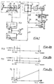
- Fig. 1 is a schematic illustration of part of a control system for an internal combustion engine in a motor vehicle in accordance with one embodiment of the invention
- Figs 2a, 2b and 2c are graphical illustrations of the states of the threshold switches of Fig. 1 and the ratio of potentiometer slider voltage to potentiometer supply voltage against position of accelerator pedal or regulating member.
- a first potentiometer 11 is associated with an accelerator pedal 12 such that its slider 13 is moved along its track in synchronism with movement of the accelerator pedal 12.
- a signal drawn from the slider 13 is passed over line 14 to one input of a comparater 15 which through a power amplifier 16, provides actuating signals to a servo motor 17 for actuation of a butterfly valve 18 in the intake manifold system 19 of an internal combustion engine (not shown).
- a second potentiometer 20 is associated with the butterfly valve 18 and its slider 21 is moved over its track in synchronism with movement of the butterfly valve 18.
- a signal drawn from the slider 21 is passed over line 22 to the comparater 15 as a positional feedback signal.
- depression of the accelerator pedal 12 by the driver indicates a desired position of the butterfly valve 18 and the servo motor 17 is actuated until the positional feedback signal provided by the potentiometer 20 balances the signal provided by the first potentiometer 11.
- an engine speed reduction device is provided and is indicated generally at 24 and operates in a "fail safe” manner in that for normal operation it is energised. When de-energised or unoperated it effects a reduction in the engine speed either by cutting off the supply of fuel to the engine or by discontinuing the ignition system or in any other suitable manner.
- a third potentiometer 25 associated with the accelerator pedal 12 and having a slider 26 which is moved over its track in synchronism with the slider 13 of the first potentiometer 11.
- a signal from the slider26 is passed over line 27 to a first threshold switch TS1 which provides an output signal on line 28 when the incoming voltage signal on line 27 is equal to or exceeds a predetermined voltage V1.
- TS1 a first threshold switch which provides an output signal on line 28 when the incoming voltage signal on line 27 is equal to or exceeds a predetermined voltage V1.
- the horizontal scale represents the position of the accelerator pedal 12 or the butterfly valve 18 with the released or engine idling position at the left and the fully depressed or fully opened positional at the right.
- the vertical axis represents the voltage signal VS at a potentiometer slider whilst in figure 2b the vertical axis represents the condition of the first threshold switch 1, 0 corresponding to the switch open position and 1 to the switch closed position.
- the threshold value switch TS1 changes state to produce an output signal which is present during the remainder of the travel of the accelerator pedal to its fully depressed condition
- a forth potentiometer 29 is associated with the regulating member 18 and its slider 30 is moved along its track in synchronism with the slider 21 of the second potentiometer 20.
- a signal from the slider 30 is passed on line 31 to a second threshold value switch TS2 which provides an output signal on line 32 until the input signal on line 31 is equal to or greater than a predetermined value V2 whereupon the threshold value switch changes state and no longer provides an output signal.
- a second threshold value switch TS2 which provides an output signal on line 32 until the input signal on line 31 is equal to or greater than a predetermined value V2 whereupon the threshold value switch changes state and no longer provides an output signal.
- the output signals on lines 28 and 32 are fed to the engine speed reduction device 24. So long as either of the threshold value switches provides an output signal the device 24 will remain operated but whenever there is a discrepancy between the actual position of the butterfly valve 18 and the desired position as identified by the accelerator pedal 12 such that neither of the threshold value switches provides an output signal, the device 24 will then be released to discontinue the supply of fuel to the engine and/or to discontinue the ignition system. The engine speed is reduced and the danger of "runaway" is avoided.
- the two potentiometers 11 and 25 and likewise the two potentiometers 20 and 29. can be combined in that the two sliders 13 and 26. and likewise 21 and 30. can travel over a common track thereby enabling the two sliders in each case to be moved substantially in synchronism with one another.
- the sliders 13 and 26 in normal operation produce substantially equivalent signals it is possible in an emergency, for example with breakdown of the potentiometer 11. 13. to utilise the signal from the slider 26 of the potentiometer 25 as the command signal to the comparater 15 and an emergency change-over switch 33 may be provided for this purpose.
- an emergency change-over switch 34 may be associated with the potentiometers 20 and 29.
Abstract
Description
- STATE OF THE ART, the present invention relates to a control system for an internal combustion engine in a motor vehicle in accordance with the precharacterising clause of claim 1 (compare with EP-A-276 003).
- The present invention is more particularly concerned with a sensor system for providing a signal characterising the position of a vehicle driver operated command member and/or of a control member in a control system for an internal combustion engine.
- In the control of an internal combustion engine in a motor vehicle it is necessary to actuate a regulating member in the form of a butterfly valve in the intake manifold system of the engine in response to driver actuation of the accelerator pedal. Originally a mechanical linkage was used for this purpose and later a Bowden cable was preferred. Recently advances in electronic control systems have lead to the provision of a servo system for the regulating member and the first sensor responsive to the position of the accelerator pedal is in the form of a potentiometer and provides a control signal indicative of a desired position. A second sensor responsive to the actual position of the regulating member is also in the form of a potentiometer and provides a feedback signal indicative of the actual position of the regulating member. These signals are passed to a comparaterwhich controls actuating signals to a servo motor which actuates the regulating member.
- The absence of a direct mechanical connection between the accelerator pedal and the regulating member has lead to the need of some form of safety device for preventing "runaway" i.e. excessive engine speed such as could be caused by substantial disconformity between the actual position of the regulating member and the desired position as determined by the accelerator pedal; thus disconformity could arise if the regulating member were in a wide open position when the accelerator pedal were in an engine idling position. For this purpose switch contacts have been provided on the accelerator pedal and on the regulating member for controlling an engine speed reduction device. The switch contacts associated with the accelerator pedal are normally open and are closed after the pedal has been actuated a predetermined extent, whilst the switch contacts associated with the regulating member are normally closed and are opened when the regulating member has been moved a predetermined extent from its engine idling position. Both the switch contacts are connected in parallel to control the engine speed reduction device which is not normally operated and which when released effectively stops the engine, for example by discontinuing the fuel supply or the ignition system. One system operating in this manner is disclosed in United States Patent Specification No. 4305359.
- During normal engine running the engine speed reduction device is operated. When the accelerator pedal is released and the regulating member is in the engine idling position, the circuit to the device is through the switch contacts associated with the regulating member whereas when the accelerator pedal is depressed more than a predetermined extent the switch contacts associated with the accelerator pedal close and provide a circuit for the device. As the regulating member is moved way from its engine idling position, at a predetermined point in its travel the switch contacts associated with the regulating member are opened so that the circuit to the device is only through the switch contacts associated with the accelerator pedal. Ideally one of the switch contacts would close as the other opens but there is no guarantee that the regulating member will move in synchronism with the accelerator pedal and allowance has to be made for some time delay. Additionally, setting of the switch contacts to be actuated at precisely corresponding positions of the regulating member and accelerator pedal presents great difficulties and so, as a compromise, an overlap of closure of the switch contacts has to be arranged. A further disadvantage is that in the event of failure of the potentiometer associated with the accelerator pedal only a very restricted form of control based on the switch contacts associated therewith is possible and this control is virtually only two stage.
- Advantages of the Present Invention. A control system in accordance with the characterising clause of
claim 1 overcomes these disadvantages. - By replacing the switch contacts associated with the accelerator pedal by a potentiometer and a threshold switch it is possible to control and adjust the position of the accelerator pedal at which a switching operation takes place and when it is desired to change that position, the change can be effected electrically rather than mechanically by selecting the voltage at which the threshold switch operates. This makes it unnecessary to adjust switch contacts mechanically in relation to the accelerator pedal.
- By using the feature of
claim 2 the advantages achieved in connection with the accelerator pedal can also be obtained in respect of the regulating member thereby making it possible for the voltages at which the respective threshold switch is operated, and thereby the corresponding positions of the accelerator pedal and regulating member, to be adjusted, maintained, or changed as desired. - The features of claims 5 and 6 greatly facilitate the sliders of the potentiometers moving in synchronism with each other and thus that the voltage signal provided by the slider of the third or fourth potentiometer respectively will correspond with a fair degree of accuracy with the voltage signals drawn from the sliders of the first and second potentiometers as command signal and feedback signal.
- The features of claim 7 and 8 provide for useful emergency operation in the event of failure of the first and/or second potentiometer since the signals drawn from the sliders of the third and fourth potentiometer respectively substantially correspond with those signals that would have been withdrawn from the sliders of the first and second potentiometers and can be used respectively for the same purposes. Thereby a continuously variable emergency control can be provided in the event of breakdown of the first and/or second potentiometer.
- DRAWINGS, the invention will be further described by way of example with reference to the accompanying drawings in which Fig. 1 is a schematic illustration of part of a control system for an internal combustion engine in a motor vehicle in accordance with one embodiment of the invention, and Figs 2a, 2b and 2c are graphical illustrations of the states of the threshold switches of Fig. 1 and the ratio of potentiometer slider voltage to potentiometer supply voltage against position of accelerator pedal or regulating member.
- Referring initially to Fig. 1 a
first potentiometer 11 is associated with anaccelerator pedal 12 such that its slider 13 is moved along its track in synchronism with movement of theaccelerator pedal 12. A signal drawn from the slider 13 is passed over line 14 to one input of acomparater 15 which through apower amplifier 16, provides actuating signals to a servo motor 17 for actuation of abutterfly valve 18 in the intake manifold system 19 of an internal combustion engine (not shown). Asecond potentiometer 20 is associated with thebutterfly valve 18 and itsslider 21 is moved over its track in synchronism with movement of thebutterfly valve 18. A signal drawn from theslider 21 is passed overline 22 to thecomparater 15 as a positional feedback signal. In operation, depression of theaccelerator pedal 12 by the driver indicates a desired position of thebutterfly valve 18 and the servo motor 17 is actuated until the positional feedback signal provided by thepotentiometer 20 balances the signal provided by thefirst potentiometer 11. - In the absence of a direct mechanical connection between the accelerator pedal and the
butterfly valve 18 it is necessary to make some provision to avoid the establishment of "runaway" conditions such as might arise for example if thebutterfly valve 18 were in a fully open position whilst theaccelerator pedal 12 was released and in an engine idling condition. For this purpose an engine speed reduction device is provided and is indicated generally at 24 and operates in a "fail safe" manner in that for normal operation it is energised. When de-energised or unoperated it effects a reduction in the engine speed either by cutting off the supply of fuel to the engine or by discontinuing the ignition system or in any other suitable manner. Associated with the device 24 are athird potentiometer 25 associated with theaccelerator pedal 12 and having aslider 26 which is moved over its track in synchronism with the slider 13 of thefirst potentiometer 11. A signal from the slider26 is passed over line 27 to a first threshold switch TS1 which provides an output signal online 28 when the incoming voltage signal on line 27 is equal to or exceeds a predetermined voltage V1. This is illustrated graphically in Figure 2b and Figure 2c. The horizontal scale represents the position of theaccelerator pedal 12 or thebutterfly valve 18 with the released or engine idling position at the left and the fully depressed or fully opened positional at the right. In figure 2c the vertical axis represents the voltage signal VS at a potentiometer slider whilst in figure 2b the vertical axis represents the condition of thefirst threshold switch accelerator pedal 12 is depressed the slider voltage VS increases and that when it reaches the value V1 the threshold value switch TS1 changes state to produce an output signal which is present during the remainder of the travel of the accelerator pedal to its fully depressed condition A forth potentiometer 29 is associated with the regulatingmember 18 and itsslider 30 is moved along its track in synchronism with theslider 21 of thesecond potentiometer 20. A signal from theslider 30 is passed online 31 to a second threshold value switch TS2 which provides an output signal on line 32 until the input signal online 31 is equal to or greater than a predetermined value V2 whereupon the threshold value switch changes state and no longer provides an output signal. This is illustrated graphically in figures 2a and 2c. The output signals onlines 28 and 32 are fed to the engine speed reduction device 24. So long as either of the threshold value switches provides an output signal the device 24 will remain operated but whenever there is a discrepancy between the actual position of thebutterfly valve 18 and the desired position as identified by theaccelerator pedal 12 such that neither of the threshold value switches provides an output signal, the device 24 will then be released to discontinue the supply of fuel to the engine and/or to discontinue the ignition system. The engine speed is reduced and the danger of "runaway" is avoided. - The two
potentiometers potentiometers 20 and 29. can be combined in that the twosliders 13 and 26. and likewise 21 and 30. can travel over a common track thereby enabling the two sliders in each case to be moved substantially in synchronism with one another. Moreover by virtue of the fact that thesliders 13 and 26 in normal operation produce substantially equivalent signals it is possible in an emergency, for example with breakdown of thepotentiometer 11. 13. to utilise the signal from theslider 26 of thepotentiometer 25 as the command signal to thecomparater 15 and an emergency change-overswitch 33 may be provided for this purpose. In a similar manner an emergency change-overswitch 34 may be associated with thepotentiometers 20 and 29.
Claims (10)
Applications Claiming Priority (1)
| Application Number | Priority Date | Filing Date | Title |
|---|---|---|---|
| PCT/EP1988/001162 WO1990007054A1 (en) | 1988-12-15 | 1988-12-15 | Control system for an internal combustion engine in a motor vehicle |
Publications (3)
| Publication Number | Publication Date |
|---|---|
| EP0401224A1 EP0401224A1 (en) | 1990-12-12 |
| EP0401224B1 true EP0401224B1 (en) | 1992-01-02 |
| EP0401224B2 EP0401224B2 (en) | 1994-11-17 |
Family
ID=8165355
Family Applications (1)
| Application Number | Title | Priority Date | Filing Date |
|---|---|---|---|
| EP89900241A Expired - Lifetime EP0401224B2 (en) | 1988-12-15 | 1988-12-15 | Control system for an internal combustion engine in a motor vehicle |
Country Status (5)
| Country | Link |
|---|---|
| US (1) | US5327865A (en) |
| EP (1) | EP0401224B2 (en) |
| JP (1) | JP2693989B2 (en) |
| DE (1) | DE3867488D1 (en) |
| WO (1) | WO1990007054A1 (en) |
Families Citing this family (15)
| Publication number | Priority date | Publication date | Assignee | Title |
|---|---|---|---|---|
| US5133321A (en) * | 1991-05-10 | 1992-07-28 | Hering Charles A | Integrated throttle control and idle validation sensor |
| US5321980A (en) * | 1991-05-10 | 1994-06-21 | Williams Controls, Inc. | Integrated throttle position sensor with independent position validation sensor |
| DE4115647B4 (en) * | 1991-05-14 | 2006-06-01 | Robert Bosch Gmbh | Control system in a vehicle |
| DE69324338T2 (en) * | 1992-12-21 | 1999-08-26 | Honda Motor Co Ltd | Device for controlling the position of an actuator |
| JP2855393B2 (en) * | 1993-02-05 | 1999-02-10 | 本田技研工業株式会社 | Control device for internal combustion engine |
| US5415144A (en) * | 1994-01-14 | 1995-05-16 | Robertshaw Controls Company | Throttle position validation method and apparatus |
| DE4411630C1 (en) * | 1994-04-02 | 1995-06-08 | Audi Ag | Control system for throttle flap in combustion engine |
| AU690404B2 (en) * | 1994-12-27 | 1998-04-23 | Komatsu Limited | Device and method for limiting the vehicle speed of a working vehicle |
| US5555873A (en) * | 1995-02-16 | 1996-09-17 | Nolen; Jay A. | Fuel tank switching apparatus |
| JP3296222B2 (en) * | 1996-12-19 | 2002-06-24 | トヨタ自動車株式会社 | Throttle control device |
| DE19719518B4 (en) * | 1997-05-09 | 2008-04-30 | Robert Bosch Gmbh | Method and device for controlling a drive unit of a motor vehicle |
| DE59813559D1 (en) * | 1998-08-12 | 2006-06-29 | Siemens Ag | METHOD FOR DETERMINING A POSITION DEPENDING ON THE MEASUREMENT SIGNAL OF A POSITION SENSOR |
| JP3694406B2 (en) * | 1998-08-28 | 2005-09-14 | 株式会社日立製作所 | Fail-safe control device for electric throttle type internal combustion engine |
| CN102269060B (en) * | 2011-07-05 | 2013-09-18 | 昆山力久新能源汽车技术有限公司 | Safety handling method of electronic accelerator signals for automobile |
| CN104527648B (en) * | 2014-12-05 | 2018-02-16 | 深圳市汇川技术股份有限公司 | Automobile double accelerator pedal signal processing method and system |
Family Cites Families (12)
| Publication number | Priority date | Publication date | Assignee | Title |
|---|---|---|---|---|
| US4393833A (en) * | 1977-12-02 | 1983-07-19 | Vdo Adolf Schindling Ag | Device for the control of the traveling speed of a motor vehicle |
| DE2839467C2 (en) * | 1978-09-11 | 1985-01-31 | Vdo Adolf Schindling Ag, 6000 Frankfurt | Device for transmitting the position of a control element which controls the driving speed of a motor vehicle and can be actuated by the vehicle driver |
| DE3237535A1 (en) * | 1982-10-09 | 1984-04-12 | Vdo Adolf Schindling Ag, 6000 Frankfurt | DEVICE FOR CONTROLLING THE SPEED OF A MOTOR VEHICLE |
| JPS59190441A (en) * | 1983-04-11 | 1984-10-29 | Nissan Motor Co Ltd | Accelerator controller for vehicle |
| JPS59190445A (en) * | 1983-04-11 | 1984-10-29 | Nissan Motor Co Ltd | Accelerator controller for vehicle |
| JPS60159346A (en) * | 1984-01-31 | 1985-08-20 | Nissan Motor Co Ltd | Traveling controller for vehicle |
| DE3510173C2 (en) * | 1984-08-16 | 1994-02-24 | Bosch Gmbh Robert | Monitoring device for an electronically controlled throttle valve in a motor vehicle |
| DE3612904A1 (en) * | 1986-04-17 | 1987-10-22 | Bosch Gmbh Robert | METHOD FOR TOLERANCE COMPENSATION OF A POSITION SENSOR SIGNAL |
| JP2662949B2 (en) * | 1986-11-29 | 1997-10-15 | 富士重工業株式会社 | Control method for automatic transmission |
| DE3643946A1 (en) * | 1986-12-22 | 1988-06-23 | Vdo Schindling | ELECTRICAL SET POINT |
| JPH0689698B2 (en) * | 1987-01-23 | 1994-11-09 | 株式会社日立製作所 | Internal combustion engine controller |
| US4920939A (en) * | 1989-02-27 | 1990-05-01 | Ford Motor Company | Position sensor monitoring system |
-
1988
- 1988-12-15 EP EP89900241A patent/EP0401224B2/en not_active Expired - Lifetime
- 1988-12-15 US US07/573,200 patent/US5327865A/en not_active Expired - Fee Related
- 1988-12-15 WO PCT/EP1988/001162 patent/WO1990007054A1/en active IP Right Grant
- 1988-12-15 JP JP63508066A patent/JP2693989B2/en not_active Expired - Fee Related
- 1988-12-15 DE DE8989900241T patent/DE3867488D1/en not_active Expired - Lifetime
Also Published As
| Publication number | Publication date |
|---|---|
| JPH03502718A (en) | 1991-06-20 |
| WO1990007054A1 (en) | 1990-06-28 |
| JP2693989B2 (en) | 1997-12-24 |
| EP0401224A1 (en) | 1990-12-12 |
| DE3867488D1 (en) | 1992-02-13 |
| US5327865A (en) | 1994-07-12 |
| EP0401224B2 (en) | 1994-11-17 |
Similar Documents
| Publication | Publication Date | Title |
|---|---|---|
| EP0401224B1 (en) | Control system for an internal combustion engine in a motor vehicle | |
| US4367805A (en) | Governing control apparatus for automobiles | |
| US4848297A (en) | Arrangement for an automotive vehicle particularly a linkage system | |
| CA1164975A (en) | Automatic speed control for heavy vehicles | |
| GB2040503A (en) | Device for controlling the fuel-air mixture of an engine | |
| EP0107265B1 (en) | Throttle system | |
| US4641622A (en) | Apparatus for throttle valve control | |
| US4488527A (en) | Device for controlling the speed of travel of an automotive vehicle | |
| US4434469A (en) | Automatic speed control system for an automotive vehicle | |
| EP0110226A3 (en) | Internal combustion engine control system with means for reshaping of command derived from accelerator control | |
| DE2900461A1 (en) | Speed control system for vehicle - has distance measuring radar automatically braking vehicle but capable of being overridden by accelerator pedal | |
| JP2510716B2 (en) | Load adjuster | |
| US4461254A (en) | Device for controlling the position of an element which controls the fuel-air mixture | |
| JPS60146734A (en) | Device for controlling speed of automobile | |
| JPH074295A (en) | Fuel controller and detecting method of trouble thereof | |
| US4785781A (en) | Device for transmitting the position of a control element which can be actuated by the driver of a vehicle | |
| US5050552A (en) | System for electronically controlling the power of an internal combustion engine of a motor vehicle | |
| US4850320A (en) | Electrical gas pedal | |
| US4993383A (en) | Controller unit | |
| US5036813A (en) | Load-shifting device | |
| US4960091A (en) | Safety circuit for electronic velocity control or regulating systems for motor vehicles | |
| US4505357A (en) | Device for electrically controlling the speed of travel | |
| US4640246A (en) | Road and engine speed governor with power demand control | |
| US5134979A (en) | Load adjustment device | |
| US4756378A (en) | System and method for controlling a vehicle speed through adjustment of a throttle valve of an engine |
Legal Events
| Date | Code | Title | Description |
|---|---|---|---|
| PUAI | Public reference made under article 153(3) epc to a published international application that has entered the european phase |
Free format text: ORIGINAL CODE: 0009012 |
|
| 17P | Request for examination filed |
Effective date: 19900714 |
|
| AK | Designated contracting states |
Kind code of ref document: A1 Designated state(s): DE GB |
|
| 17Q | First examination report despatched |
Effective date: 19910305 |
|
| GRAA | (expected) grant |
Free format text: ORIGINAL CODE: 0009210 |
|
| AK | Designated contracting states |
Kind code of ref document: B1 Designated state(s): DE GB |
|
| REF | Corresponds to: |
Ref document number: 3867488 Country of ref document: DE Date of ref document: 19920213 |
|
| RAP4 | Party data changed (patent owner data changed or rights of a patent transferred) |
Owner name: ROBERT BOSCH GMBH |
|
| PLBI | Opposition filed |
Free format text: ORIGINAL CODE: 0009260 |
|
| 26 | Opposition filed |
Opponent name: VDO ADOLF SCHINDLING AG Effective date: 19920919 Opponent name: SIEMENS AG GR PA 5 Effective date: 19920921 |
|
| PUAH | Patent maintained in amended form |
Free format text: ORIGINAL CODE: 0009272 |
|
| STAA | Information on the status of an ep patent application or granted ep patent |
Free format text: STATUS: PATENT MAINTAINED AS AMENDED |
|
| 27A | Patent maintained in amended form |
Effective date: 19941117 |
|
| AK | Designated contracting states |
Kind code of ref document: B2 Designated state(s): DE GB |
|
| PGFP | Annual fee paid to national office [announced via postgrant information from national office to epo] |
Ref country code: GB Payment date: 19961202 Year of fee payment: 9 |
|
| PG25 | Lapsed in a contracting state [announced via postgrant information from national office to epo] |
Ref country code: GB Free format text: LAPSE BECAUSE OF NON-PAYMENT OF DUE FEES Effective date: 19971215 |
|
| GBPC | Gb: european patent ceased through non-payment of renewal fee |
Effective date: 19971215 |
|
| PGFP | Annual fee paid to national office [announced via postgrant information from national office to epo] |
Ref country code: DE Payment date: 20040210 Year of fee payment: 16 |
|
| PG25 | Lapsed in a contracting state [announced via postgrant information from national office to epo] |
Ref country code: DE Free format text: LAPSE BECAUSE OF NON-PAYMENT OF DUE FEES Effective date: 20050701 |