EP0401188B1 - Control system for a paper or board machine - Google Patents
Control system for a paper or board machine Download PDFInfo
- Publication number
- EP0401188B1 EP0401188B1 EP90850215A EP90850215A EP0401188B1 EP 0401188 B1 EP0401188 B1 EP 0401188B1 EP 90850215 A EP90850215 A EP 90850215A EP 90850215 A EP90850215 A EP 90850215A EP 0401188 B1 EP0401188 B1 EP 0401188B1
- Authority
- EP
- European Patent Office
- Prior art keywords
- control system
- actuator
- control
- profile
- web
- Prior art date
- Legal status (The legal status is an assumption and is not a legal conclusion. Google has not performed a legal analysis and makes no representation as to the accuracy of the status listed.)
- Revoked
Links
- 238000005259 measurement Methods 0.000 claims abstract description 38
- 238000004891 communication Methods 0.000 claims abstract description 15
- 230000001105 regulatory effect Effects 0.000 claims abstract description 14
- 238000000034 method Methods 0.000 claims abstract description 8
- 230000033228 biological regulation Effects 0.000 claims description 21
- 239000011248 coating agent Substances 0.000 claims description 8
- 238000000576 coating method Methods 0.000 claims description 8
- 238000012546 transfer Methods 0.000 claims description 5
- 238000003490 calendering Methods 0.000 claims description 4
- 230000001276 controlling effect Effects 0.000 claims description 3
- 238000012937 correction Methods 0.000 claims description 3
- 238000004364 calculation method Methods 0.000 claims description 2
- 230000001939 inductive effect Effects 0.000 claims description 2
- 238000001035 drying Methods 0.000 description 7
- 239000000725 suspension Substances 0.000 description 4
- 230000005540 biological transmission Effects 0.000 description 3
- 230000007547 defect Effects 0.000 description 3
- 238000010438 heat treatment Methods 0.000 description 3
- 238000004804 winding Methods 0.000 description 3
- 238000006243 chemical reaction Methods 0.000 description 2
- 230000002950 deficient Effects 0.000 description 2
- 230000005611 electricity Effects 0.000 description 2
- 238000012423 maintenance Methods 0.000 description 2
- 238000012544 monitoring process Methods 0.000 description 2
- 101000741965 Homo sapiens Inactive tyrosine-protein kinase PRAG1 Proteins 0.000 description 1
- 102100038659 Inactive tyrosine-protein kinase PRAG1 Human genes 0.000 description 1
- 241001180873 Saposhnikovia divaricata Species 0.000 description 1
- 230000004913 activation Effects 0.000 description 1
- 238000001514 detection method Methods 0.000 description 1
- 238000010586 diagram Methods 0.000 description 1
- 230000000694 effects Effects 0.000 description 1
- 238000005516 engineering process Methods 0.000 description 1
- 230000006698 induction Effects 0.000 description 1
- 238000009434 installation Methods 0.000 description 1
- 238000012806 monitoring device Methods 0.000 description 1
- 230000010355 oscillation Effects 0.000 description 1
- 230000002265 prevention Effects 0.000 description 1
- 238000004886 process control Methods 0.000 description 1
- 230000004044 response Effects 0.000 description 1
- 230000001360 synchronised effect Effects 0.000 description 1
- 238000004260 weight control Methods 0.000 description 1
Images



Classifications
-
- D—TEXTILES; PAPER
- D21—PAPER-MAKING; PRODUCTION OF CELLULOSE
- D21G—CALENDERS; ACCESSORIES FOR PAPER-MAKING MACHINES
- D21G9/00—Other accessories for paper-making machines
- D21G9/0009—Paper-making control systems
- D21G9/0027—Paper-making control systems controlling the forming section
-
- D—TEXTILES; PAPER
- D21—PAPER-MAKING; PRODUCTION OF CELLULOSE
- D21F—PAPER-MAKING MACHINES; METHODS OF PRODUCING PAPER THEREON
- D21F7/00—Other details of machines for making continuous webs of paper
- D21F7/06—Indicating or regulating the thickness of the layer; Signal devices
-
- G—PHYSICS
- G01—MEASURING; TESTING
- G01N—INVESTIGATING OR ANALYSING MATERIALS BY DETERMINING THEIR CHEMICAL OR PHYSICAL PROPERTIES
- G01N33/00—Investigating or analysing materials by specific methods not covered by groups G01N1/00 - G01N31/00
- G01N33/34—Paper
- G01N33/346—Paper sheets
Definitions
- the invention concerns a control system for a paper or board machine, by means of which the transverse profile of properties of the web to be produced, in particular its thickness profile, is regulated, said control system comprising a number of actuators and a corresponding number (N pcs.) of actuator controllers, said actuators being fitted to be effective across the width of the web whose profile is to be regulated, and said control system including a process computer or an equivalent logical component as well as a feedback branch provided with an arrangement for measurement of the web profile to be regulated.
- a pulp suspension jet is fed out of the discharge opening in paper or board machines onto the forming wire or into the gap between the forming wires.
- the transverse profile of the discharge opening of the headbox also determines the profile of the pulp jet.
- the profile of the discharge opening is regulated, and by means of this regulation it is also possible to compensate for any flaws in the pulp jet that have arisen in or before the headbox.
- a control system for the grammage profile lip of the headbox of a paper machine which system comprises an angle-gear/stepping motor control device, wherein the profile bar of the regulator lips is controlled by means of adjusting spindles attached to the profile bar at intervals of about 10...15 cm, said spindles being displaced by stepping motors attached to their opposite ends by the intermediate of angle gears.
- the prior-art control systems for adjusting spindles involve a number of drawbacks, most of which come from the fact that the control of each actuator takes place separately directly from the system placed at a higher level in the hierarchy, which results, e.g., in the following drawbacks:
- the profiling of the profile bar of the discharge opening of the headbox takes place by separate control of each regulation gear by means of handling sequences carried out one after the other.
- electronics that measure the locations of the adjusting spindles are also required.
- the positioning takes place about 5 seconds per actuator, and the reading of measurement alone takes 1.2 seconds.
- running through all of the actuators on a profile bar with 80 adjusting spindles takes from 1.5 to 6.5 minutes. Information is obtained on the state of an actuator momentarily only.
- the systems of cables from the processor cabinet are arranged by means of two system cables and electricity supply cables from the dry spaces to the wiring cabinet placed at the headbox (distance 50 to 250 meters), from where separate cables are passed to the location detector and stepping motor of each actuator (10 to 30 meters).
- the profile of the web that is being produced is regulated by means of devices in which, at least partly, the same problems are present as in the above prior-art systems for the regulation of the profile of the discharge opening of the headbox.
- the present invention is not confined to a control system for the discharge opening of a headbox alone, but it can be applied in various regulation devices for paper and board machines as well as for their finishing equipment by means of which devices the transverse profile of properties of the web is controlled.
- the invention is mainly characterized in that the various actuators in the control system are provided with intelligent actuator controllers and that the data communications in the control hierarchy between a higher control device and the various actuator controllers are arranged along a bus common of the various actuator controllers.
- the controlling apparatus placed at a higher level in the control hierarchy may be a bus server specifically provided for this purpose, said server transferring set values from the automation system to the actuators and status and measurement values from the actuator towards the system.
- the automation system may also control the actuators directly based on a certain line protocol.
- the bus between the automation system and the series of actuators may consist of a simple asynchronous line. Thus, one cable only is required to pass to the entire series of actuators. Moreover, operating electricity is needed for the control card and for the stepping motors.
- the system at the higher level is free from load; the regulation/measurement takes place in the actuators independently and simultaneously.
- the regulation does not load the system, and the speed of operation is substantially higher than in prior art.
- each individual actuator that regulates the transverse profile of the web is arranged as an independent positioning device, which is, when necessary, capable of monitoring its own operation in real time.
- the actuators are connected to the system for the calculation of profiling by means of a serial bus, whereby the amount of operations taking place at the same time is limited by the data transfer speed or by the capacity of the power source only.
- a data transfer speed of, e.g., 19,200 bauds is used for the control of the 80 spindles in the headbox while the message length is 8+6 bytes, for every actuator a new set value is obtained in less than two seconds. If it is desired to carry out the invention so that only ten (10) actuators are operative at one time, the positioning of all of the actuators takes less than half a minute.
- the system of cables between the control system and the series of actuators can be accomplished by means of a comb-like voltage and data distribution chain, to which the actuator controllers themselves are connected in direct proximity of the actuator, which consists, e.g., of a gear, a position detector, and of a motor.
- the electronic systems of the actuators can be accomplished as standard modules, which are identical in the case of each actuator.
- each device can be given its own code by means of rotating switches provided on a card, whereupon the device can operate correctly in the bus when it recognizes its own code.
- the higher controlling system transmits set values for all the actuators through the bus, and it can read the measurement value as well as the status, which contains status and error data.
- the electronics card of each individual actuator has preferably its own processor, memory, serial-communication electronics, integrated control electronics for the stepping motor, and an A/D-converter for carrying out the measurement from a LVDT-detector.
- the software contained in the card handles the serial communications upwards, the control of the stepping motor on the basis of the set values given, and the feedback measurement regarding the completion of the adjustment.
- a quantity that is changed within normal limits is compensated for by, on the basis of an algorithm, calculating a suitable correction for the regulation or measurement.
- control and the diagnostics are based on software makes the device easily adaptable to different purposes of use and to different environments and even to control mechanics of a different type. Later fine tuning and improved algorithms can also be integrated in the device without difficulty.
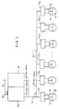
- Figure A illustrates the prior art that constitutes the starting point of the invention, in respect of the regulation of the discharge opening of a headbox.
- Figure 1 is a schematical illustration of a paper machine and of related finishing equipment, in connection with which a control system and a series of actuator controllers in accordance with the invention are applied.
- Figure 2 is a schematical and partly axonometric view of a control system in accordance with the invention as applied to the regulation of the discharge opening of the headbox of a paper machine.
- Figure 3 shows the principle of accomplishing of a control system and an actuator controller in accordance with the invention, in a way corresponding to Fig. A.
- Figure 4 shows a block diagram of an actuator controller.
- Fig. A shows a prior-art profile regulation system for the discharge opening of the headbox of a paper machine.
- the system comprises N pcs. of measurement-stepping-motor units C1...C N placed side by side, by means of which units the adjusting spindles (Fig. 2, parts 311...313), which are connected to the profile bar that profiles the discharge opening, are regulated and measured.
- the control message is passed into each unit C1...C N from the wiring cabinet B2 through 6-pole separate cables f1...f N and, in a corresponding way, the measurement messages of the units C1...C N are transferred to the measurement unit B1 placed in connection with the wiring cabinet B2 from each unit by means of its own 5-pole cable e1...e N .
- the prior-art control system comprises a central unit (CPU) A1, a source A2 of electric power.
- the central unit A1 receives the signals from the operation and maintenance station through the cable a, and the data on the profile of the paper web through the cable b.
- This prior-art control system involves the drawbacks discussed above, which drawbacks are eliminated efficiently by the present invention.
- Fig. 1 illustrates various objects of application of the control system and actuator controller in accordance with the invention in paper or board machines and in related on-line finishing equipment.
- Fig. 1 is a schematical presentation of just one exemplifying embodiment of a paper machine, and the invention is in no way confined to said example, but it may be applied to a number of different paper or board machines wherein it is necessary to regulate the transverse profile of properties of the web that is being produced, in particular its thickness profile but, if necessary, also other profiles of properties, such as smoothness profile.
- the paper machine shown in Fig. 1 includes a wire part 11, which consists of an upper wire 11a and of a lower wire 11b.
- the headbox 10 feeds a pulp suspension jet, whose transverse profile is controlled in accordance with the invention, onto the initial part of the lower wire.
- a twin-wire portion 11c From the lower wire 11b the web is detached at the pick-up point P, being transferred into the press section onto the upper felt 12a, on whose lower face the web W is passed into the first nip N1 in the press section, said nip being a two-felt 12a,12b nip.
- the web W follows the upper felt 12a and is transferred into the second nip N2, from which the web W is transferred on the smooth face of the centre roll in the press into the third nip N3, and from it further onto the fourth felt 14a in the press.
- Fig. 1 shows, of the end portion of the pre-dryer, the upper drying wire 14c and the lower drying wire 14d as well as the last drying cylinders 14d.
- the dryer is followed by an on-line coating device, which is provided with blade coaters 16 and with a coating nip N L , after which the web W is transferred into an after-dryer, which comprises drying cylinders 16b and a drying wire 16a.
- Fig. 1 shows the last drying cylinders 16b and the lower wire 16c of the after-dryer, after which the web W passes through a calendering nip N K and from there further onto the Pope-type reel-up 19.
- control system 100 in accordance with the invention and the related actuator controllers are applied to profiling of the discharge opening in a headbox 10, to control of the adjusting spindles of the steam box 13 placed between the press nips N1 and N2 in connection with the suction roll, to profiling of the coating blade in the blade coater 16, and/or to profiling of the calendering nip N K by means of inductive heating devices 17.
- the control system 100 is provided with a feedback branch, wherein the properties of the web W, e.g.
- Said web profile measurement devices 15 and 18 are connected to the control system 100 by means of the connections m1 and m2.
- the control system 100 controls the series of the various actuators through the connections c1,c2,c3 and c4, said series comprising the actuator controllers in accordance with the present invention, which will be described later.
- the data on the positions and status of the various actuators are also transferred through the connections c1,c2,c3 and c4 to the control system 100.
- Fig. 1 the control system 100 and the paper machine are shown highly schematically, and Fig. 1 is just intended to illustrate various fields of application of the invention wherein a transverse profile of properties of the web W to be produced is regulated.
- Fig. 2 is a more detailed illustration of an application of the invention to the regulation of the transverse profile of the pulp suspension jet J discharged out of the discharge opening A of the headbox 10 of a paper machine onto the forming wire 11b.
- the headbox 10 is primarily known in prior art, and, starting from the discharge opening A and going in the direction opposite to the direction of flow F of the pulp suspension, it comprises first a discharge duct 21, then a turbulence generator 22, an equalizing chamber 25, a set of distribution tubes 23, and a distributor beam 24.
- the profile bar 30 is fixed, which determines the profile of the discharge opening A and thereby the transverse profile of the pulp jet.
- the individual actuator controllers 42 are connected to a common cable 41, which has a part 44 with rake-like division.
- the cable 41 is an, e.g., 7-pole cable, and it has four poles connected to the network server 40 and three poles connected to the source 49 of electric power.
- the controller parts 42 are connected to the measurement part 34 and to the stepping-motor part 33 by means of cables 45.
- the network server 40 receives the control signals through a cable 48 from the operator station 47 and, through cables 46, the control signals from the web W profile measurement and control computer 101.
- Fig. 2 shows a web profile measurement station 15, in which, in connection with a system of measurement beams 26 and with a carriage 28 moving on said system of beams, there is a web profile measurement detector 27, from which the measurement signal m1 is obtained.
- Said measurement signal m1 is passed to the measurement and control computer 101, whose operation and maintenance station is denoted with the reference numeral 102. From the computer 101, the profile control data are fed through the cable 46 to the network server 40.
- the cable 41 and its rake part 44 form a part of the serial bus so that the amount of simultaneous operations is limited by the speed of data transfer or by the capacity of the power source only.
- each operator controller 42 consists of five operational sections, which are: measurement part 58,59,59a; control part 51; current source 52; processor part 54,55,56,57, and switchboard panel.
- LVDT-detectors 59 are used, to whose primary winding a suitable AC-voltage is supplied.
- Operation amplifier rectifiers placed in the secondary windings of the detectors 59 rectify the AC-voltages, which are obtained from the winding halves and which are proportional to the movement of the spindle 31.
- the output voltage is measured by means of an A/D-converter 58, and the processor unit 54 reads the A/D-converter 58 through a synchronous serial bus made of I/O-gates and places the conversion result obtained in the RAM 56.
- the control electronics of the stepping motor 33 consist of power transistors, return diodes being connected in parallel with said transistors.
- the current passing through the stepping motor 33 is stabilized by means of comparators, which cut the control of the power transistors when the current in the stepping motor becomes excessively high.
- the controls proper of the power transistors are obtained, as optoisolated, from the gates of the CPU 54.
- the processor part 54...57 consists, e.g., of an Intel CPU 80 ⁇ C31, which in itself contains 15 I/O-gates, USART, as well as two 8-bit counters.
- the capacity of the program memory 55 is, e.g., 65 kB, and the capacity of data memory 56 is 8 kB as a battery-powered RAM and 128 bytes as an EEPROM 52.
- the EEPROM 57 the scaling coefficient of the measurement as well as the operation point of the measurement are stored.
- the control of the stepping motor 33 is carried out by means of buffered and optically isolated I/O-gates. Upon switching on of the voltages, the effects of said controls are prevented until the reset of the CPU 54 is removed and the carrying out of the program is started.
- a watchdog monitors the operation of the programs and, in the first stage, resets the CPU 58 unless the program resets the watchdog to zero 200 ms.
- the processor part also includes the transmitter-receivers of the connection 53, which adapt the 0 ⁇ -5 V voltage level used by the USART of the CPU to the RS 422 standard.
- the communications between the actuator controllers 42 and the network server 40 take place along the RS422 connection. It is electrically compatible also with a RS485 interface.
- the communications take place with 9 bits, so that, when the starting signal (STX) of a message is transmitted, the last bit to be transmitted is "I" but, when other signals of a message is transmitted, "0". All actuators that have activated the detection of the 9th bit in their USART receive the starting signal. Having received the starting signal, the actuators activate their USART to receive such signals whose last bit is "0", because all the subsequent bytes in a message will be transmitted so that the last bit to be transmitted is "0".
- the communications between the network server 40 and the actuator controllers 42 take place with the question-reply principle, wherein the network server 40 acts as the master of the bus.
- a message consists of a frame composed of a starting signal STX, an address ADDRESS, message type MESSAGE, message length LENGTH, a check sum BCC, as well as of an end signal ETX.
- the length of the address field in the frame is 8 bits, so that, at the maximum, 255 actuators can be connected to the network.
- the formats of the message data and frame are binary. Normally an actuator replies to a question message with a reply message except in situations of error, in which case the actuator transmits a reject message (NACK) to the service unit. Error situations identified by the actuator in the communications include:
- the network server 40 identifies the same error situations in message communications as the actuator does. Moreover, the network server 40 monitors the time taken between a question message and a reply message and, upon elapse of the time-out between messages (5 seconds), repeats the transmission of the message. The transmissions of renewal messages are repeated 5 times and, unless the actuator controller 42 replies, the service unit stops communicating with the actuator controller concerned. In an error situation, the above operation also takes place when the actuator controller 42 acknowledges a message transmitted to it by means of a reject message. In an error situation, the communications with other actuator controllers 42 are interrupted, at the maximum, for 25 seconds. The service unit reports a defective actuator to the process level in a higher-level error message.
- the actuator controllers 421...42 N communicate with the process computer/process station by the intermediate of the RS422-interface 53.
- the set values are transmitted to the actuator, said set values being 16-bit 2-complement numbers.
- the set values are given as »m, so that, within said number range, a control range of 65,536 »m is obtained.
- the zero point of the set values is the centre point of the measurement range of the LVDT-detectors, determined on mechanical resetting to zero of the discharge opening A.
- the actuator controllers 421...42 N measure the locations of the adjusting spindles 311...31 N independently and monitor the rationality of the measurement values. In a situation of measurement error, the actuator judges the nature of the defect and, based on its seriousness, either just reports the defect or prohibits adjustment of the spindle 31 concerned by setting it in prohibition of adjustment.
- the measurement of location is carried out by means of a double-integrating A/D-converter, whose conversion cycle lasts about 200 ms. This is why, by means of the measurement, it is not possible to detect high-frequency oscillation in the location of the spindle 31.
- the spindles 311...31 N coupled with the angle gears 32 are adjusted by means of stepping motors 33, in which one adjustment step displaces the spindle 31 by about 1.2 »m.
- the running of the spindle 31 to a new set value takes place in four steps:
- the spindles 31 do not necessarily reach the new set value with one attempt.
- the operator may determine the maximum number of attempts, after which the actuator 42 notifies of an adjustment error if the set value has not been reached.
- the actuator determines for itself a so-called control index number, by means of whose examination the service operator can judge the tightness of an angle gear.
- the control output stage of the stepping motors is provided with a thermostat activated by an excessively high temperature in the output stage circuits, said thermostat preventing control of the stepping motors 33.
- the activation of the thermostat is reported by the actuator 42 to the process computer, which must take into account the prevention of adjustment in its deflection limit monitoring. If desired, the thermostat can be acknowledged and disregarded from the process station or from any other monitoring device. In a situation of control error, the actuator places itself in running prohibition, which can, however, be disregarded by the operator.
- the actuators monitor their operations and report any errors in operation to the higher level of process control. If the defect is serious, the actuator switches the operating voltages off, in which case the actuator does not reply to the question messages from the network server 40.
Landscapes
- Health & Medical Sciences (AREA)
- Life Sciences & Earth Sciences (AREA)
- Chemical & Material Sciences (AREA)
- Engineering & Computer Science (AREA)
- Food Science & Technology (AREA)
- Medicinal Chemistry (AREA)
- Physics & Mathematics (AREA)
- Analytical Chemistry (AREA)
- Biochemistry (AREA)
- General Health & Medical Sciences (AREA)
- General Physics & Mathematics (AREA)
- Immunology (AREA)
- Pathology (AREA)
- Paper (AREA)
- Preparing Plates And Mask In Photomechanical Process (AREA)
- Auxiliary Devices For And Details Of Packaging Control (AREA)
- Chemical Vapour Deposition (AREA)
Abstract
Description
- The invention concerns a control system for a paper or board machine, by means of which the transverse profile of properties of the web to be produced, in particular its thickness profile, is regulated, said control system comprising a number of actuators and a corresponding number (N pcs.) of actuator controllers, said actuators being fitted to be effective across the width of the web whose profile is to be regulated, and said control system including a process computer or an equivalent logical component as well as a feedback branch provided with an arrangement for measurement of the web profile to be regulated.
- As is known from prior art, a pulp suspension jet is fed out of the discharge opening in paper or board machines onto the forming wire or into the gap between the forming wires. The transverse profile of the discharge opening of the headbox also determines the profile of the pulp jet. The profile of the discharge opening is regulated, and by means of this regulation it is also possible to compensate for any flaws in the pulp jet that have arisen in or before the headbox.
- In prior art, a control system for the grammage profile lip of the headbox of a paper machine is known, which system comprises an angle-gear/stepping motor control device, wherein the profile bar of the regulator lips is controlled by means of adjusting spindles attached to the profile bar at intervals of about 10...15 cm, said spindles being displaced by stepping motors attached to their opposite ends by the intermediate of angle gears. The prior-art control systems for adjusting spindles involve a number of drawbacks, most of which come from the fact that the control of each actuator takes place separately directly from the system placed at a higher level in the hierarchy, which results, e.g., in the following drawbacks:
- the stepping motors are controlled in parallel, so that several wires are required for each individual actuator, because normally the number of actuators is about 50 to 100,
- as the actuators have no local intelligence, the control system placed higher in the hierarchy has to take care of the regulation of all of the actuators at the same time, which, of course, burdens said regulation system particularly heavily,
- owing to said burdening, the speed of the system also remains low and the response times become long,
- since all the actuators are regulated in the same way, local conditions and mechanical differences, e.g., in the angle gears, cannot be taken into account, so that the accuracy of regulation is deficient and detecting of erroneous operations is difficult.
- As has come out above at least partly, by means of the prior-art technology, the profiling of the profile bar of the discharge opening of the headbox takes place by separate control of each regulation gear by means of handling sequences carried out one after the other. In order that the positioning should be successful with the required accuracy of about 10 »m, electronics that measure the locations of the adjusting spindles are also required. Typically, the positioning takes place about 5 seconds per actuator, and the reading of measurement alone takes 1.2 seconds. Thus, running through all of the actuators on a profile bar with 80 adjusting spindles takes from 1.5 to 6.5 minutes. Information is obtained on the state of an actuator momentarily only.
- As is known in prior art, the systems of cables from the processor cabinet are arranged by means of two system cables and electricity supply cables from the dry spaces to the wiring cabinet placed at the headbox (distance 50 to 250 meters), from where separate cables are passed to the location detector and stepping motor of each actuator (10 to 30 meters).
- In paper and board machines and in related size presses, coating devices and calenders, the profile of the web that is being produced is regulated by means of devices in which, at least partly, the same problems are present as in the above prior-art systems for the regulation of the profile of the discharge opening of the headbox. Thus, the present invention is not confined to a control system for the discharge opening of a headbox alone, but it can be applied in various regulation devices for paper and board machines as well as for their finishing equipment by means of which devices the transverse profile of properties of the web is controlled. In addition to the devices mentioned above, further prior-art devices that affect the transverse profile of the web are, for example, steam boxes fitted in the press section of a paper machine, devices for profiling of the coating blades in a coating machine, as well as electric induction heating devices fitted, e.g., in connection with calender rolls, by means of which heating devices the profile of linear loads in a calendering nip is controlled.
- Prior-art control systems suffering from the above-mentioned drawbacks are disclosed in TAPPI JOURNAL, Vol. 67, No. 12, December 1984, Atlanta US, pages 52-55: STEVEN J. SILER; "Cross-machine basis-weight control: machine considerations"; US-A-3 666 621, US-A-4 748 400 and EP-A-0 041 486. All these prior-art systems comprise actuators which are separately controlled directly from a control device placed at a higher level in the hierarchy.
- In view of achieving the objectives stated above and those that will come out later, the invention is mainly characterized in that the various actuators in the control system are provided with intelligent actuator controllers and that the data communications in the control hierarchy between a higher control device and the various actuator controllers are arranged along a bus common of the various actuator controllers.
- In the control system in accordance with the invention, the regulation is based on decentralized intelligence of actuators, which is just parametered by the higher system by giving the set values. Each actuator controller is seen upwards as an independent unit, to which a set value is given in digital form along the serial bus, whereupon the actuator controller handles the mechanical regulation independently in accordance with its own measurement-regulation algorithm.
- The controlling apparatus placed at a higher level in the control hierarchy may be a bus server specifically provided for this purpose, said server transferring set values from the automation system to the actuators and status and measurement values from the actuator towards the system. The automation system may also control the actuators directly based on a certain line protocol.
- The bus between the automation system and the series of actuators may consist of a simple asynchronous line. Thus, one cable only is required to pass to the entire series of actuators. Moreover, operating electricity is needed for the control card and for the stepping motors.
- Having transmitted the set values to the actuators, the system at the higher level is free from load; the regulation/measurement takes place in the actuators independently and simultaneously. Thus, the regulation does not load the system, and the speed of operation is substantially higher than in prior art.
- In the invention, each individual actuator that regulates the transverse profile of the web is arranged as an independent positioning device, which is, when necessary, capable of monitoring its own operation in real time. The actuators are connected to the system for the calculation of profiling by means of a serial bus, whereby the amount of operations taking place at the same time is limited by the data transfer speed or by the capacity of the power source only. In the invention, if a data transfer speed of, e.g., 19,200 bauds is used for the control of the 80 spindles in the headbox while the message length is 8+6 bytes, for every actuator a new set value is obtained in less than two seconds. If it is desired to carry out the invention so that only ten (10) actuators are operative at one time, the positioning of all of the actuators takes less than half a minute.
- In the invention, the system of cables between the control system and the series of actuators can be accomplished by means of a comb-like voltage and data distribution chain, to which the actuator controllers themselves are connected in direct proximity of the actuator, which consists, e.g., of a gear, a position detector, and of a motor.
- The electronic systems of the actuators can be accomplished as standard modules, which are identical in the case of each actuator. In connection with the installation, each device can be given its own code by means of rotating switches provided on a card, whereupon the device can operate correctly in the bus when it recognizes its own code. Thus, the higher controlling system transmits set values for all the actuators through the bus, and it can read the measurement value as well as the status, which contains status and error data.
- The electronics card of each individual actuator has preferably its own processor, memory, serial-communication electronics, integrated control electronics for the stepping motor, and an A/D-converter for carrying out the measurement from a LVDT-detector. The software contained in the card handles the serial communications upwards, the control of the stepping motor on the basis of the set values given, and the feedback measurement regarding the completion of the adjustment. During running, if necessary, it is possible to examine, e.g., the operating temperature, the stiffness of the transmission system, the accuracy of the regulation, etc. quantities in whose values a substantial change causes an error message and discontinuation of the regulation. A quantity that is changed within normal limits is compensated for by, on the basis of an algorithm, calculating a suitable correction for the regulation or measurement.
- The fact that the control and the diagnostics are based on software makes the device easily adaptable to different purposes of use and to different environments and even to control mechanics of a different type. Later fine tuning and improved algorithms can also be integrated in the device without difficulty.
- In the following, the invention and the prior art most closely related to same will be described in detail with reference to the figures in the accompanying drawing and to some advantageous exemplifying embodiments of the invention illustrated in said figures.
- Figure A illustrates the prior art that constitutes the starting point of the invention, in respect of the regulation of the discharge opening of a headbox.
- Figure 1 is a schematical illustration of a paper machine and of related finishing equipment, in connection with which a control system and a series of actuator controllers in accordance with the invention are applied.
- Figure 2 is a schematical and partly axonometric view of a control system in accordance with the invention as applied to the regulation of the discharge opening of the headbox of a paper machine.
- Figure 3 shows the principle of accomplishing of a control system and an actuator controller in accordance with the invention, in a way corresponding to Fig. A.
- Figure 4 shows a block diagram of an actuator controller.
- Fig. A shows a prior-art profile regulation system for the discharge opening of the headbox of a paper machine. The system comprises N pcs. of measurement-stepping-motor units C₁...CN placed side by side, by means of which units the adjusting spindles (Fig. 2,
parts 31₁...31₃), which are connected to the profile bar that profiles the discharge opening, are regulated and measured. The control message is passed into each unit C₁...CN from the wiring cabinet B₂ through 6-pole separate cables f₁...fN and, in a corresponding way, the measurement messages of the units C₁...CN are transferred to the measurement unit B₁ placed in connection with the wiring cabinet B₂ from each unit by means of its own 5-pole cable e₁...eN. The prior-art control system comprises a central unit (CPU) A₁, a source A₂ of electric power. The central unit A₁ receives the signals from the operation and maintenance station through the cable a, and the data on the profile of the paper web through the cable b. Between the central unit A₁ and the wiring cabinet B₁ there are two 32-pole cables c and d. This prior-art control system involves the drawbacks discussed above, which drawbacks are eliminated efficiently by the present invention. - Fig. 1 illustrates various objects of application of the control system and actuator controller in accordance with the invention in paper or board machines and in related on-line finishing equipment. Fig. 1 is a schematical presentation of just one exemplifying embodiment of a paper machine, and the invention is in no way confined to said example, but it may be applied to a number of different paper or board machines wherein it is necessary to regulate the transverse profile of properties of the web that is being produced, in particular its thickness profile but, if necessary, also other profiles of properties, such as smoothness profile.
- The paper machine shown in Fig. 1 includes a
wire part 11, which consists of anupper wire 11a and of alower wire 11b. Theheadbox 10 feeds a pulp suspension jet, whose transverse profile is controlled in accordance with the invention, onto the initial part of the lower wire. Hereupon there follows a twin-wire portion 11c. From thelower wire 11b the web is detached at the pick-up point P, being transferred into the press section onto the upper felt 12a, on whose lower face the web W is passed into the first nip N₁ in the press section, said nip being a two-felt 12a,12b nip. After the first nip N₁ the web W follows the upper felt 12a and is transferred into the second nip N₂, from which the web W is transferred on the smooth face of the centre roll in the press into the third nip N₃, and from it further onto thefourth felt 14a in the press. - Fig. 1 shows, of the end portion of the pre-dryer, the upper drying wire 14c and the
lower drying wire 14d as well as thelast drying cylinders 14d. The dryer is followed by an on-line coating device, which is provided withblade coaters 16 and with a coating nip NL, after which the web W is transferred into an after-dryer, which comprises dryingcylinders 16b and adrying wire 16a. Fig. 1 shows thelast drying cylinders 16b and the lower wire 16c of the after-dryer, after which the web W passes through a calendering nip NK and from there further onto the Pope-type reel-up 19. - As is shown in Fig. 1, the
control system 100 in accordance with the invention and the related actuator controllers are applied to profiling of the discharge opening in aheadbox 10, to control of the adjusting spindles of thesteam box 13 placed between the press nips N₁ and N₂ in connection with the suction roll, to profiling of the coating blade in theblade coater 16, and/or to profiling of the calendering nip NK by means ofinductive heating devices 17. As is shown in Fig. 1, thecontrol system 100 is provided with a feedback branch, wherein the properties of the web W, e.g. its transverse thickness profile, are measured by means of a traversingmeasurement detector 15 or a corresponding series of detectors, placed after the drying section, and by means of a corresponding measurement beam 18 fitted after the calender, in connection with which beam there may also be measurement of the transverse smoothness profile or equivalent of the web W. - Said web
profile measurement devices 15 and 18 are connected to thecontrol system 100 by means of the connections m₁ and m₂. Thecontrol system 100 controls the series of the various actuators through the connections c₁,c₂,c₃ and c₄, said series comprising the actuator controllers in accordance with the present invention, which will be described later. The data on the positions and status of the various actuators are also transferred through the connections c₁,c₂,c₃ and c₄ to thecontrol system 100. - It should be stated that, in Fig. 1, the
control system 100 and the paper machine are shown highly schematically, and Fig. 1 is just intended to illustrate various fields of application of the invention wherein a transverse profile of properties of the web W to be produced is regulated. - Fig. 2 is a more detailed illustration of an application of the invention to the regulation of the transverse profile of the pulp suspension jet J discharged out of the discharge opening A of the
headbox 10 of a paper machine onto the formingwire 11b. Theheadbox 10 is primarily known in prior art, and, starting from the discharge opening A and going in the direction opposite to the direction of flow F of the pulp suspension, it comprises first adischarge duct 21, then aturbulence generator 22, an equalizingchamber 25, a set ofdistribution tubes 23, and adistributor beam 24. To the front wall of the upper lip beam, in a way known in itself, theprofile bar 30 is fixed, which determines the profile of the discharge opening A and thereby the transverse profile of the pulp jet. - The
profile bar 30 is attached to adjustingspindles 31₁...31N. If the spindles 31 are at distances of, e.g., 10 cm from one another, a paper machine of a width of about 8 m comprises 80 pcs. of adjusting spindles (N = 80). Each adjusting spindle 31 is connected with anangle gear 32, by whose intermediate the stepping motors 31 displace the spindles 31 in their longitudinal direction. Each individual angle-gear/stepping-motor unit intelligent actuator controller 42₁...42N of its own by the intermediate of acable 45. Saidcontrollers 42₁...42N are identical with one another, and an advantageous exemplifying embodiment thereof will be described in more detail later, in particular with reference to Figs. 4 and 5. - The
individual actuator controllers 42 are connected to acommon cable 41, which has apart 44 with rake-like division. Thecable 41 is an, e.g., 7-pole cable, and it has four poles connected to thenetwork server 40 and three poles connected to thesource 49 of electric power. Thecontroller parts 42 are connected to themeasurement part 34 and to the stepping-motor part 33 by means ofcables 45. Thenetwork server 40 receives the control signals through acable 48 from theoperator station 47 and, throughcables 46, the control signals from the web W profile measurement andcontrol computer 101. - Fig. 2 shows a web
profile measurement station 15, in which, in connection with a system ofmeasurement beams 26 and with acarriage 28 moving on said system of beams, there is a webprofile measurement detector 27, from which the measurement signal m₁ is obtained. Said measurement signal m₁ is passed to the measurement andcontrol computer 101, whose operation and maintenance station is denoted with thereference numeral 102. From thecomputer 101, the profile control data are fed through thecable 46 to thenetwork server 40. - According to the present invention, the
intelligent actuator controllers 42, which are identical with each other and whose number is N pcs. (as a rule, N = 10...100), operate, each of them, as independent positioning devices, which also monitor their own operations in real time. Thecable 41 and itsrake part 44 form a part of the serial bus so that the amount of simultaneous operations is limited by the speed of data transfer or by the capacity of the power source only. When a data transfer speed of 19,200 bauds is used and when the message length is 8+6 bytes, a new set value is obtained for eachcontroller 42, when the number of spindles 31 is N = 80, in a time shorter than 2 s. - According to Fig. 4, the electronic system of each
operator controller 42 consists of five operational sections, which are:measurement part part 51;current source 52;processor part - For the measurement of the movements of the lower ends of the
spindles 31₁...31N, LVDT-detectors 59 are used, to whose primary winding a suitable AC-voltage is supplied. Operation amplifier rectifiers placed in the secondary windings of thedetectors 59 rectify the AC-voltages, which are obtained from the winding halves and which are proportional to the movement of the spindle 31. The output voltage is measured by means of an A/D-converter 58, and theprocessor unit 54 reads the A/D-converter 58 through a synchronous serial bus made of I/O-gates and places the conversion result obtained in theRAM 56. - The control electronics of the stepping
motor 33 consist of power transistors, return diodes being connected in parallel with said transistors. The current passing through the steppingmotor 33 is stabilized by means of comparators, which cut the control of the power transistors when the current in the stepping motor becomes excessively high. The controls proper of the power transistors are obtained, as optoisolated, from the gates of theCPU 54. - The
processor part 54...57 consists, e.g., of an Intel CPU 80̸C31, which in itself contains 15 I/O-gates, USART, as well as two 8-bit counters. The capacity of theprogram memory 55 is, e.g., 65 kB, and the capacity ofdata memory 56 is 8 kB as a battery-powered RAM and 128 bytes as anEEPROM 52. In theEEPROM 57, the scaling coefficient of the measurement as well as the operation point of the measurement are stored. The control of the steppingmotor 33 is carried out by means of buffered and optically isolated I/O-gates. Upon switching on of the voltages, the effects of said controls are prevented until the reset of theCPU 54 is removed and the carrying out of the program is started. A watchdog monitors the operation of the programs and, in the first stage, resets theCPU 58 unless the program resets the watchdog to zero 200 ms. The processor part also includes the transmitter-receivers of theconnection 53, which adapt the 0̸-5 V voltage level used by the USART of the CPU to theRS 422 standard. - The communications between the
actuator controllers 42 and thenetwork server 40 take place along the RS422 connection. It is electrically compatible also with a RS485 interface. The communications take place with 9 bits, so that, when the starting signal (STX) of a message is transmitted, the last bit to be transmitted is "I" but, when other signals of a message is transmitted, "0". All actuators that have activated the detection of the 9th bit in their USART receive the starting signal. Having received the starting signal, the actuators activate their USART to receive such signals whose last bit is "0", because all the subsequent bytes in a message will be transmitted so that the last bit to be transmitted is "0". - The communications between the
network server 40 and theactuator controllers 42 take place with the question-reply principle, wherein thenetwork server 40 acts as the master of the bus. - A message consists of a frame composed of a starting signal STX, an address ADDRESS, message type MESSAGE, message length LENGTH, a check sum BCC, as well as of an end signal ETX. The length of the address field in the frame is 8 bits, so that, at the maximum, 255 actuators can be connected to the network. The formats of the message data and frame are binary. Normally an actuator replies to a question message with a reply message except in situations of error, in which case the actuator transmits a reject message (NACK) to the service unit. Error situations identified by the actuator in the communications include:
- incorrect message type
- incorrect message length
- incorrect check sum
- time-out between signals has elapsed
- end signal of message missing
- The
network server 40 identifies the same error situations in message communications as the actuator does. Moreover, thenetwork server 40 monitors the time taken between a question message and a reply message and, upon elapse of the time-out between messages (5 seconds), repeats the transmission of the message. The transmissions of renewal messages are repeated 5 times and, unless theactuator controller 42 replies, the service unit stops communicating with the actuator controller concerned. In an error situation, the above operation also takes place when theactuator controller 42 acknowledges a message transmitted to it by means of a reject message. In an error situation, the communications withother actuator controllers 42 are interrupted, at the maximum, for 25 seconds. The service unit reports a defective actuator to the process level in a higher-level error message. - The
actuator controllers 42₁...42N communicate with the process computer/process station by the intermediate of the RS422-interface 53. By means of message communications taking place along theconnection 53, the set values are transmitted to the actuator, said set values being 16-bit 2-complement numbers. The set values are given as »m, so that, within said number range, a control range of 65,536 »m is obtained. The zero point of the set values is the centre point of the measurement range of the LVDT-detectors, determined on mechanical resetting to zero of the discharge opening A. - The
actuator controllers 42₁...42N measure the locations of the adjustingspindles 31₁...31N independently and monitor the rationality of the measurement values. In a situation of measurement error, the actuator judges the nature of the defect and, based on its seriousness, either just reports the defect or prohibits adjustment of the spindle 31 concerned by setting it in prohibition of adjustment. The measurement of location is carried out by means of a double-integrating A/D-converter, whose conversion cycle lasts about 200 ms. This is why, by means of the measurement, it is not possible to detect high-frequency oscillation in the location of the spindle 31. - The
spindles 31₁...31N coupled with the angle gears 32 are adjusted by means of steppingmotors 33, in which one adjustment step displaces the spindle 31 by about 1.2 »m. The running of the spindle 31 to a new set value takes place in four steps: - step 1:
- the play in the angle gear and the location of the spindle in relation to the play are measured,
- step 2:
- the spindle is run to the calculated new set value; the play is taken into account when the running direction is changed,
- step 3:
- checking measurement is carried out,
- step 4:
- a correction run is carried out if necessary.
- Owing to differences in tightness in angle gears 32, the spindles 31 do not necessarily reach the new set value with one attempt. The operator may determine the maximum number of attempts, after which the
actuator 42 notifies of an adjustment error if the set value has not been reached. - On the basis of the number of attempts needed to reach a new set value, the actuator determines for itself a so-called control index number, by means of whose examination the service operator can judge the tightness of an angle gear.
- The control output stage of the stepping motors is provided with a thermostat activated by an excessively high temperature in the output stage circuits, said thermostat preventing control of the stepping
motors 33. The activation of the thermostat is reported by theactuator 42 to the process computer, which must take into account the prevention of adjustment in its deflection limit monitoring. If desired, the thermostat can be acknowledged and disregarded from the process station or from any other monitoring device. In a situation of control error, the actuator places itself in running prohibition, which can, however, be disregarded by the operator. - The actuators monitor their operations and report any errors in operation to the higher level of process control. If the defect is serious, the actuator switches the operating voltages off, in which case the actuator does not reply to the question messages from the
network server 40. - In the following, the patent claims will be given, and the various details of the invention may show variation within the scope of the inventive idea defined in said claims and differ from the details stated above for the sake of example only.
Claims (10)
- Control system for a paper or board machine, by means of which the transverse profile of properties of the web (W) to be produced, in particular its thickness profile, is regulated, said control system comprising a number of actuators (30,31,32) and a corresponding number (N pcs.) of actuator controllers (42), said actuators being fitted to be effective across the width of the web (W) whose profile is to be regulated, and said control system including a process computer (101) or an equivalent logical component as well as a feedback branch provided with an arrangement (15,26,27,28;18) for measurement of the web profile to be regulated, characterized in that the various actuators (30,31,32) in the control system are provided with intelligent actuator controllers (42₁...42N) and that the data communications in the control hierarchy between a higher control device (101,40) and the various actuator controllers (42₁...42N) are arranged along a bus (41) common of the various actuator controllers (42₁...42N).
- Control system as claimed in claim 1, characterized in that the various actuator controllers (42₁...42N) are connected to the system of measurement and calculation (15,101) of the profiling of the web (W) to be profiled by means of a serial bus (41), which is provided with a network server (40).
- Control system as claimed in claim 1 or 2, characterized in that, in the control system, decentralized intelligence is employed, which is just parametered by the higher system in the control hierarchy by giving the set values, that each actuator controller (42₁...42N) is seen upwards in the hierarchy as an independent unit, to which the set values are given in digital form along the serial bus (41), whereupon the actuator controllers (41₁...42N) control the mechanical regulation to take place independently in accordance with their own measurement-regulation algorithms, and that the controlling apparatus placed at a higher level in the control hierarchy is a network server (40), which transfers set values from the automation system to the actuator controllers (42₁...42N) and status and/or measurement values from the actuator controllers (42₁...42N) towards the system.
- Control system as claimed in any of the claims 1 to 3, characterized in that the electronic systems of the actuator controllers (42₁...42N) are accomplished as standard modules, which are substantially identical with one another in each actuator controller.
- Control system as claimed in any of the claims 1 to 4, characterized in that the electronic card of each of the various actuator controllers (42₁...42N) includes a processor (54) of its own, memory and serial-communication electronics (53,55,56,57), actuator-motor (33) control electronics (51), and converter electronics (58) for the measurement detector (59) of the movement of the actuator (31).
- Control system as claimed in claim 5, characterized in that, in said electronic card, programs have been stored that are arranged to take care of communications in the serial bus (41).
- Control system as claimed in claim 5 or 6, characterized in that the electronics of the actuator controller (42₁...42N) are arranged to examine the operating temperature of the actuator, its mechanical properties, precision of adjustment, and/or corresponding quantities, a substantial change in said values causing an error message and discontinuation of regulation, and that a quantity that changes within normal limits is arranged to be compensated for by, on the basis of an algorithm, calculating a suitable correction for the regulation or measurement.
- Control system as claimed in claims 1 to 7, characterized in that the actuator controllers (42₁...42N) are arranged to control the adjusting spindles (31₁...31N) of the profile bar (30) of the head box of a paper machine, preferably by the intermediate of an angle gear (32) and a stepping motor (30) (Fig. 2).
- Control system as claimed in any of the claims 1 to 8, characterized in that the system is fitted to control a series of profiling actuators of the coating blade or equivalent of a paper-web (W) coating device (16,NL).
- Control system as claimed in any of the claims 1 to 9, characterized in that the control system is fitted to control a steam box (13) fitted at the proximity of the web, the profile of linear loads in a press nip of a paper machine, and/or the profile of linear loads in a calendering nip (NK) in an on-line calender of a paper machine, the latter one preferably by making use of an inductive profiling device (17) (Fig. 1).
Applications Claiming Priority (2)
| Application Number | Priority Date | Filing Date | Title |
|---|---|---|---|
| FI892670A FI85731C (en) | 1989-06-01 | 1989-06-01 | Control system in a paper or cardboard machine |
| FI892670 | 1989-06-01 |
Publications (3)
| Publication Number | Publication Date |
|---|---|
| EP0401188A2 EP0401188A2 (en) | 1990-12-05 |
| EP0401188A3 EP0401188A3 (en) | 1991-09-18 |
| EP0401188B1 true EP0401188B1 (en) | 1995-02-22 |
Family
ID=8528550
Family Applications (1)
| Application Number | Title | Priority Date | Filing Date |
|---|---|---|---|
| EP90850215A Revoked EP0401188B1 (en) | 1989-06-01 | 1990-05-25 | Control system for a paper or board machine |
Country Status (6)
| Country | Link |
|---|---|
| US (1) | US5381341A (en) |
| EP (1) | EP0401188B1 (en) |
| AT (1) | ATE118845T1 (en) |
| CA (1) | CA2018114C (en) |
| DE (1) | DE69017083T2 (en) |
| FI (1) | FI85731C (en) |
Families Citing this family (32)
| Publication number | Priority date | Publication date | Assignee | Title |
|---|---|---|---|---|
| WO1991018146A1 (en) * | 1990-05-24 | 1991-11-28 | Vickerys Limited | Improvements relating to the manufacture of sheet material |
| WO1995015492A1 (en) * | 1993-12-02 | 1995-06-08 | Siemens Aktiengesellschaft | Process and device for monitoring the cross-sectional shape of a continuously produced web of material |
| FI94066C (en) * | 1994-05-16 | 1995-07-10 | Valmet Paper Machinery Inc | Comprehensive management system for the various cross-section profiles of a paper web produced on a web material making machine such as a board or paper machine and / or a finishing machine |
| GB9411908D0 (en) * | 1994-06-14 | 1994-08-03 | John Heyer Paper Ltd | Web monitoring for paper machines |
| ATE180026T1 (en) * | 1994-12-19 | 1999-05-15 | Siemens Ag | METHOD FOR DETECTING AND INFLUENCING THE TRANSVERSE PROFILES OF CERTAIN PROPERTIES OF PAPER WEBS AND ASSOCIATED ARRANGEMENT |
| JPH08313223A (en) * | 1995-05-16 | 1996-11-29 | Ls Electro Galvanizing Co | Method and apparatus for monitoring moving strips |
| US5603806A (en) * | 1995-06-01 | 1997-02-18 | Valmet Corporation | Method and apparatus for lateral alignment of the cross-direction quality profile of a web in a paper machine |
| US5771174A (en) * | 1995-12-21 | 1998-06-23 | Measurex Corporation | Distributed intelligence actuator controller with peer-to-peer actuator communication |
| US5812404A (en) * | 1996-04-18 | 1998-09-22 | Valmet Corporation | Method for overall regulation of the headbox of a paper machine or equivalent |
| US5825653A (en) * | 1997-03-14 | 1998-10-20 | Valmet Corporation | Method for overall regulation of a former of a paper machine or equivalent |
| JP3372430B2 (en) * | 1996-09-11 | 2003-02-04 | オークマ株式会社 | Synchronous control device |
| FI100345B (en) * | 1997-01-24 | 1997-11-14 | Valmet Corp | Method and apparatus for paper machine headbox adjustment |
| US6284100B1 (en) | 1997-01-24 | 2001-09-04 | Valmet Corporation | Method and apparatus for controlling a headbox in a paper machine |
| DE59707751D1 (en) * | 1997-02-28 | 2002-08-22 | Stowe Woodward Ag | METHOD FOR DESIGNING AND / OR VISUALIZING AT LEAST ONE ROLL / FELT PAIRING IN THE WET PRESS OF A PAPER OR CARDBOARD MACHINE |
| DE19727460A1 (en) * | 1997-06-27 | 1999-01-07 | Voith Sulzer Papiermasch Gmbh | Control and / or regulating system of a machine for producing a fibrous web |
| US6104987A (en) * | 1997-10-03 | 2000-08-15 | The Nash Engineering Company | System for monitoring dryer drum temperatures |
| FI974327L (en) * | 1997-11-25 | 1999-05-26 | Valmet Automation Inc | Method and apparatus for adjusting paper properties |
| FI108887B (en) | 1998-01-23 | 2002-04-15 | Metso Paper Automation Oy | actuator |
| FI104161B (en) * | 1998-02-17 | 1999-11-30 | Valmet Corp | Method and apparatus for web winding |
| US6094604A (en) * | 1998-03-06 | 2000-07-25 | Honeywell Measurex Devron Inc. | Coordinated control of sheet properties by receiving a measured and broadcasted properties data, determining a control action, and broadcasting a predicted changes to other actuators |
| CA2323244C (en) * | 1999-10-13 | 2008-01-08 | Valmet Corporation | Integrated machine control method and machine control module |
| US20030000669A1 (en) * | 2001-05-11 | 2003-01-02 | Invensys Systems, Inc. | Methods and systems for controlling paper quality by adjusting fiber filter parameters |
| SE521176C2 (en) * | 2001-08-15 | 2003-10-07 | Metso Paper Inc | Distribution device for even distribution and cross-distribution of a streaming medium |
| US7185537B2 (en) * | 2003-06-04 | 2007-03-06 | Metso Paper, Inc. | Nip and loading analysis system |
| US7513975B2 (en) * | 2003-06-25 | 2009-04-07 | Honeywell International Inc. | Cross-direction actuator and control system with adaptive footprint |
| US20060185809A1 (en) * | 2005-02-23 | 2006-08-24 | Abb. | Actuator system for use in control of a sheet or web forming process |
| RU2294997C1 (en) * | 2005-08-19 | 2007-03-10 | Михаил Александрович Великотный | Optical-electronic system for adjustment and diagnostics of technical condition of paper manufacturing machines (variants) |
| US8224476B2 (en) * | 2010-05-31 | 2012-07-17 | Honeywell Asca Inc. | Closed-loop monitoring and identification of CD alignment for papermaking processes |
| KR101300174B1 (en) * | 2011-10-26 | 2013-08-26 | (주)로보티즈 | Method for controling network structure-based actuator module |
| DE202012012642U1 (en) | 2012-07-18 | 2013-07-24 | Voith Patent Gmbh | Actuator and actuator system for a transverse and / or longitudinal profile adjustment |
| CN103616497B (en) * | 2013-11-29 | 2015-10-28 | 绵阳同成智能装备股份有限公司 | High-speed paper machine paper quality on-line measuring device |
| EP3299133B1 (en) * | 2015-05-22 | 2020-09-02 | Nissan Motor Co., Ltd. | Failure diagnosis device and failure diagnosis method |
Family Cites Families (14)
| Publication number | Priority date | Publication date | Assignee | Title |
|---|---|---|---|---|
| US3666621A (en) * | 1968-02-16 | 1972-05-30 | Industrial Nucleonics Corp | Process and apparatus for moisture and fiber content control in a papermaking machine |
| FR2429867A1 (en) * | 1978-06-30 | 1980-01-25 | Centre Tech Ind Papier | CONTROLLING THE OPERATION OF THE HEADBOX OF A PAPER MACHINE |
| SE454365B (en) * | 1980-06-02 | 1988-04-25 | Svenska Traeforskningsinst | SET FOR MANAGING A PAPER PATH FEATURES TWO FEEDING DIRECTION IN A PAPER MACHINE |
| US4500968A (en) * | 1982-06-29 | 1985-02-19 | Domtar Inc. | Paper machine wet line control |
| GB8303614D0 (en) | 1983-02-09 | 1983-03-16 | Wiggins Teape Group Ltd | Controlled elongate nozzle |
| EP0106593A3 (en) * | 1982-10-11 | 1984-11-28 | The Wiggins Teape Group Limited | Nozzle control apparatus |
| US4578764A (en) * | 1983-03-07 | 1986-03-25 | Zymark Corporation | Self-configuring robotic system and method |
| US4626984A (en) * | 1984-08-29 | 1986-12-02 | Valmont Industries, Inc. | Remote computer control for irrigation systems |
| US4707779A (en) * | 1984-11-20 | 1987-11-17 | Measurex Corporation | Process for controlling a parameter based upon filtered data |
| US4680089A (en) * | 1985-01-22 | 1987-07-14 | Measurex Corporation | Process for controlling the formation of sheet material |
| US4745744A (en) * | 1986-04-08 | 1988-05-24 | Vickers, Incorporated | Power transmission |
| US4748400A (en) * | 1987-01-20 | 1988-05-31 | Impact Systems, Inc. | Method for controlling the amount of moisture associated with a web of moving material |
| US4957770A (en) * | 1989-01-27 | 1990-09-18 | Measurex Corporation | Coating weight measuring and control apparatus and method |
| US4947684A (en) * | 1989-01-27 | 1990-08-14 | Measurex Corporation | System and process for detecting properties of travelling sheets in the machine direction |
-
1989
- 1989-06-01 FI FI892670A patent/FI85731C/en active IP Right Grant
-
1990
- 1990-05-25 EP EP90850215A patent/EP0401188B1/en not_active Revoked
- 1990-05-25 AT AT90850215T patent/ATE118845T1/en not_active IP Right Cessation
- 1990-05-25 DE DE69017083T patent/DE69017083T2/en not_active Revoked
- 1990-06-01 CA CA002018114A patent/CA2018114C/en not_active Expired - Lifetime
-
1993
- 1993-02-18 US US08/020,251 patent/US5381341A/en not_active Expired - Lifetime
Also Published As
| Publication number | Publication date |
|---|---|
| CA2018114C (en) | 1998-08-11 |
| US5381341A (en) | 1995-01-10 |
| ATE118845T1 (en) | 1995-03-15 |
| CA2018114A1 (en) | 1990-12-01 |
| DE69017083T2 (en) | 1995-07-20 |
| FI85731B (en) | 1992-02-14 |
| FI892670A0 (en) | 1989-06-01 |
| DE69017083D1 (en) | 1995-03-30 |
| FI85731C (en) | 1997-08-20 |
| EP0401188A3 (en) | 1991-09-18 |
| EP0401188A2 (en) | 1990-12-05 |
| FI892670A7 (en) | 1990-12-02 |
Similar Documents
| Publication | Publication Date | Title |
|---|---|---|
| US5381341A (en) | Control system for a paper or board machine | |
| JP3914573B2 (en) | Distributed intelligence actuator controller using peer-to-peer actuator communication | |
| CA2167292C (en) | System for overall control of the different transverse profiles in a paper web manufactured by means of a machine for the manufacture of a web material, such as a board or paper machine and/or a finishing machine | |
| US6092003A (en) | Paper stock shear and formation control | |
| EP0728984B1 (en) | System for monitoring and control of the circulation lubrication of the bearings of cylinders and rolls in a paper machine | |
| CN101133209A (en) | Actuator system for controlling a sheet or web forming process | |
| US3711688A (en) | Computer control of paper machine in which basis weight is controlled through control of stock flow | |
| EP1073789B1 (en) | System of regulation for a paper machine | |
| US6094604A (en) | Coordinated control of sheet properties by receiving a measured and broadcasted properties data, determining a control action, and broadcasting a predicted changes to other actuators | |
| US6231722B1 (en) | Method and system for monitoring the process of separation of a web | |
| EP0408894B1 (en) | Method for regulation and on-line measurement of the fibre orientation in a web produced by means of a paper machine | |
| US8790495B2 (en) | Web production with increased process efficiency | |
| EP1342843B1 (en) | Method and system for controlling the web formation | |
| FI972576A0 (en) | Method for collecting and influencing information related to cross-sectional profiles of certain properties of paper webs and equipment related to the method | |
| JP3178498B2 (en) | Paper thickness control device of paper machine | |
| US6440270B1 (en) | Method and apparatus for controlling dryer section of paper machine | |
| Bakhtin et al. | Improvement of Paper Quality Management System by Web Width on the Basis of Intellectual Technologies | |
| WO1999058436A1 (en) | Method for measurement of a paper web | |
| JPH0583677B2 (en) |
Legal Events
| Date | Code | Title | Description |
|---|---|---|---|
| PUAI | Public reference made under article 153(3) epc to a published international application that has entered the european phase |
Free format text: ORIGINAL CODE: 0009012 |
|
| AK | Designated contracting states |
Kind code of ref document: A2 Designated state(s): AT DE FR GB IT SE |
|
| 17P | Request for examination filed |
Effective date: 19901228 |
|
| PUAL | Search report despatched |
Free format text: ORIGINAL CODE: 0009013 |
|
| AK | Designated contracting states |
Kind code of ref document: A3 Designated state(s): AT DE FR GB IT SE |
|
| 17Q | First examination report despatched |
Effective date: 19931112 |
|
| GRAA | (expected) grant |
Free format text: ORIGINAL CODE: 0009210 |
|
| AK | Designated contracting states |
Kind code of ref document: B1 Designated state(s): AT DE FR GB IT SE |
|
| REF | Corresponds to: |
Ref document number: 118845 Country of ref document: AT Date of ref document: 19950315 Kind code of ref document: T |
|
| REF | Corresponds to: |
Ref document number: 69017083 Country of ref document: DE Date of ref document: 19950330 |
|
| ITF | It: translation for a ep patent filed | ||
| ET | Fr: translation filed | ||
| PLBI | Opposition filed |
Free format text: ORIGINAL CODE: 0009260 |
|
| PLAV | Examination of admissibility of opposition |
Free format text: ORIGINAL CODE: EPIDOS OPEX |
|
| PLAB | Opposition data, opponent's data or that of the opponent's representative modified |
Free format text: ORIGINAL CODE: 0009299OPPO |
|
| PLBF | Reply of patent proprietor to notice(s) of opposition |
Free format text: ORIGINAL CODE: EPIDOS OBSO |
|
| 26 | Opposition filed |
Opponent name: VOITH SULZER PAPIERMASCHINEN GMBH Effective date: 19951121 |
|
| R26 | Opposition filed (corrected) |
Opponent name: VOITH SULZER PAPIERMASCHINEN GMBH Effective date: 19951121 |
|
| PLBF | Reply of patent proprietor to notice(s) of opposition |
Free format text: ORIGINAL CODE: EPIDOS OBSO |
|
| PLBF | Reply of patent proprietor to notice(s) of opposition |
Free format text: ORIGINAL CODE: EPIDOS OBSO |
|
| PLAW | Interlocutory decision in opposition |
Free format text: ORIGINAL CODE: EPIDOS IDOP |
|
| APAC | Appeal dossier modified |
Free format text: ORIGINAL CODE: EPIDOS NOAPO |
|
| APAE | Appeal reference modified |
Free format text: ORIGINAL CODE: EPIDOS REFNO |
|
| APAC | Appeal dossier modified |
Free format text: ORIGINAL CODE: EPIDOS NOAPO |
|
| RAP2 | Party data changed (patent owner data changed or rights of a patent transferred) |
Owner name: VALMET CORPORATION |
|
| PGFP | Annual fee paid to national office [announced via postgrant information from national office to epo] |
Ref country code: FR Payment date: 20000428 Year of fee payment: 11 |
|
| PGFP | Annual fee paid to national office [announced via postgrant information from national office to epo] |
Ref country code: SE Payment date: 20000516 Year of fee payment: 11 |
|
| PGFP | Annual fee paid to national office [announced via postgrant information from national office to epo] |
Ref country code: AT Payment date: 20000518 Year of fee payment: 11 |
|
| PGFP | Annual fee paid to national office [announced via postgrant information from national office to epo] |
Ref country code: GB Payment date: 20000524 Year of fee payment: 11 |
|
| PGFP | Annual fee paid to national office [announced via postgrant information from national office to epo] |
Ref country code: DE Payment date: 20000629 Year of fee payment: 11 |
|
| APAC | Appeal dossier modified |
Free format text: ORIGINAL CODE: EPIDOS NOAPO |
|
| RDAH | Patent revoked |
Free format text: ORIGINAL CODE: EPIDOS REVO |
|
| RDAG | Patent revoked |
Free format text: ORIGINAL CODE: 0009271 |
|
| STAA | Information on the status of an ep patent application or granted ep patent |
Free format text: STATUS: PATENT REVOKED |
|
| 27W | Patent revoked |
Effective date: 20000704 |
|
| GBPR | Gb: patent revoked under art. 102 of the ep convention designating the uk as contracting state |
Free format text: 20000704 |
|
| APAH | Appeal reference modified |
Free format text: ORIGINAL CODE: EPIDOSCREFNO |
|
| PLAB | Opposition data, opponent's data or that of the opponent's representative modified |
Free format text: ORIGINAL CODE: 0009299OPPO |