EP0400850B1 - Generating coefficients for digital filters - Google Patents
Generating coefficients for digital filters Download PDFInfo
- Publication number
- EP0400850B1 EP0400850B1 EP90305400A EP90305400A EP0400850B1 EP 0400850 B1 EP0400850 B1 EP 0400850B1 EP 90305400 A EP90305400 A EP 90305400A EP 90305400 A EP90305400 A EP 90305400A EP 0400850 B1 EP0400850 B1 EP 0400850B1
- Authority
- EP
- European Patent Office
- Prior art keywords
- coefficient
- coefficients
- generating
- filter
- stochastic
- Prior art date
- Legal status (The legal status is an assumption and is not a legal conclusion. Google has not performed a legal analysis and makes no representation as to the accuracy of the status listed.)
- Expired - Lifetime
Links
- 230000003044 adaptive effect Effects 0.000 claims abstract description 62
- 238000000034 method Methods 0.000 claims abstract description 53
- 230000008569 process Effects 0.000 claims abstract description 33
- 230000004044 response Effects 0.000 claims abstract description 12
- 238000012545 processing Methods 0.000 claims description 30
- 238000012935 Averaging Methods 0.000 claims description 17
- 230000014509 gene expression Effects 0.000 claims description 11
- 238000013459 approach Methods 0.000 claims description 3
- 238000012804 iterative process Methods 0.000 abstract description 20
- 238000006243 chemical reaction Methods 0.000 description 7
- 238000010586 diagram Methods 0.000 description 6
- 230000006870 function Effects 0.000 description 6
- 238000012937 correction Methods 0.000 description 4
- 238000012546 transfer Methods 0.000 description 4
- 238000005070 sampling Methods 0.000 description 3
- 230000008901 benefit Effects 0.000 description 2
- 238000001914 filtration Methods 0.000 description 2
- 230000005540 biological transmission Effects 0.000 description 1
- 238000004364 calculation method Methods 0.000 description 1
- 238000002939 conjugate gradient method Methods 0.000 description 1
- 230000001934 delay Effects 0.000 description 1
- 230000001419 dependent effect Effects 0.000 description 1
- 230000000694 effects Effects 0.000 description 1
- 230000006872 improvement Effects 0.000 description 1
Images


Classifications
-
- H—ELECTRICITY
- H03—ELECTRONIC CIRCUITRY
- H03H—IMPEDANCE NETWORKS, e.g. RESONANT CIRCUITS; RESONATORS
- H03H21/00—Adaptive networks
- H03H21/0012—Digital adaptive filters
-
- H—ELECTRICITY
- H03—ELECTRONIC CIRCUITRY
- H03H—IMPEDANCE NETWORKS, e.g. RESONANT CIRCUITS; RESONATORS
- H03H21/00—Adaptive networks
- H03H21/0012—Digital adaptive filters
- H03H2021/007—Computation saving measures; Accelerating measures
- H03H2021/0076—Measures relating to the convergence time
- H03H2021/0078—Measures relating to the convergence time varying the step size
Definitions
- the present invention relates in general to a system and method for generating coefficients for digital filters.
- the present invention more particularly relates to such a system and method wherein an iterative adaptive process is utilized which employs a least mean square processor with the step size of the filter coefficients in process being related to the stochastic average of the gradients generated during the iterative process.
- Digital filters find application in digital circuits, including those implemented in integrated circuit form. Such filters exhibit many advantages such as, for example, high reliability, no drift with time, no drift with temperature, unit-to-unit repeatability, and superior transmission performance.
- Digital filters can include one or more sections, the number of sections depending mainly upon the desired accuracy in realizing the nominal characteristics of the filter. In other words, an increase in the number of sections a digital filter provides a corresponding increase in the accuracy to which the desired filter characteristics can be obtained.
- SLAC subscriber line audio-processing circuit
- SLAC devices are utilized in telephone systems to perform CODEC and filter functions associated with the two-wire section of the subscriber line circuiting in a digital switch.
- these circuits provide conversion of analog voice signals to digital pulse code modulated (PCM) samples for placement of the PCM signals onto a PCM highway, and conversion of digital PCM signals received from the PCM highway into analog voice signals.
- PCM digital pulse code modulated
- digital filters are used to band-limit the voice signals, set gain, perform trans-hybrid balancing, provide adjustment of termination impedance, and provide frequency attenuation adjustment (equalization) of the receive and transmit paths.
- a filter coefficient for each section or tap of the filter is necessary to provide a filter coefficient for each section or tap of the filter. This is generally accomplished by storing the filter coefficient in a memory of the device employing the filter.
- the filter coefficient for each filter section is transformed from a single number into a plurality of coefficients known as Canonic Signed Digit (CSD) coefficients before storage into memory.
- CSD coefficients and the manner in which they may be derived from a single coefficient are well known in the art.
- the coefficients for the digital filter section were generated by an adaptive iterative least mean square process.
- the coefficients of the filter section have been, during each iteration, updated from the last iteration by the instantaneous gradient value.
- the instantaneous gradient based upon a single sample, is the product of the instantaneous value of a time-varying input signal and the simultaneous instantaneous value of an error signal.
- the error signal is generated by applying the input signal to both a desired filter characteristic and the filter coefficients in process to generate first and second outputs, and then generating the difference between these output.
- the process is stopped and the last set of coefficients used in the process are the final coefficients to be used in the filter after conversion to the CSD format.
- the foregoing process is sensitive to noise in generating the gradient because the gradient is based upon a single time sample.
- the prior art iterative process has required considerable time for completion to arrive at an accurate determination of digital filter coefficients given the fact that it is sensitive to noise and the variable optimum step-size is difficult to determine.
- a system for generating coefficients for use in a digital filter comprising: means for providing data indicative of a desired filter characteristic; iterative processing means for generating at least one filter coefficient and a gradient for each said iteration, said iterative processing means including means for generating a time-varying gradient estimate and means for varying said at least one coefficient during each said iteration by an amount related to the generated gradient estimate; comparing means for comparing said at least one generated coefficient to said desired filter characteristic; and means for terminating said iterative processing means when said at least one coefficient is within a given range of said desired filter characteristic, characterised in that the means for generating the time-varying gradient estimate generates the estimate in accordance with the stochastic average of the previously generated gradients such that the average is taken over a progressively increasing number of past values as the iteration process approaches convergence.
- the system is more reliable and more immune to noise at or near convergence compared to a system in which the instantaneous estimates are averaged over a fixed predetermined number of past values.
- the iterative processing means include means for generating a pair of stochastic averaging coefficients for generating the stochastic average of the gradients.
- the two coefficients may comprise an adaptive gain factor and an adaptive forgetting factor, and the means for varying the filter coefficient in each iteration may then include a correlator circuit having a first amplifier with a gain equal to the adaptive gain factor and a second amplifier having a gain equal to the forgetting factor.
- step-size is related to the stochastic average of the gradients generated during the adaptive process.
- FIG. 1 it illustrates, in block diagram form, the signal processing circuitry of a subscriber line audio-processing circuit in which the present invention may be utilized to an advantage.
- the subscriber line audio-processing circuit (SLAC) performs the CODEC and filter functions associated with the two-wire section of the subscriber line circuitry in a digital switch. In general, these functions involve converting an analog voice signal into digital pulse code modulated (PCM) samples for placing the PCM samples onto a PCM highway and converting digital PCM samples received from the PCM highway into an analog signal.
- PCM digital pulse code modulated
- the circuit 10 of Figure 1 generally includes a first input 12 for receiving analog voice signals, a first output 14 for transferring the PCM samples to a time slot assigning circuit for placement of the PCM samples onto the PCM highway, a second input 16 adapted to be coupled to the time slot assigning circuit for receiving PCM samples from the PCM highway, and a second output 18 for providing analog signals representative of the PCM samples received from the PCM highway.
- the signal processing circuitry extending between the first input 12 and the first output 14 represents the transmit signal processing path of the circuit and the signal processing circuitry from the second input 16 to the second output 18 represents the receive signal processing path of the circuit.
- the transmit signal processing path includes an amplifier 20, an analog-to-digital converter 22, a first decimator 24, a second decimator 26, an attenuator 28, a first programmable digital filter (X) 30, a high-pass filter 32, and a data compressor 34.
- the amplifier 20 is an analog amplifier and provides analog signal gain into the analog-to-digital converter 22.
- the analog-to-digital converter 22 converts the analog voice signals to PCM data samples.
- the decimators 24 and 26 reduce the high input sampling rate to 16 khz.
- the attenuator 28 provides signal level correction into the filter 30.
- the filter 30 is, for example, a six-tapp finite input response filter which provides frequency response correction.
- the high-pass filter 32 rejects low frequencies such as frequencies in the range of 50 hz or 60 hz for the purpose of filtering, for example, AC line noise.
- the compressor 34 compresses the digital PCM samples in a known manner.
- the receive signal processing circuitry includes an expander 40, a low-pass filter 42, a second programmable digital filter (R) 44, an attenuator 46, interpolators 48 and 50, a digital-to-analog converter 52, and an amplifier 54.
- the expander 40 expands the compressed digital PCM samples received from the PCM highway and the low-pass filter 42 filters the expanded digital PCM samples.
- the second programmable filter 44 is preferably a 6-tap finite input response filter which operates at a 16 khz sampling rate and provides frequency response correction.
- the attenuator 46 provides signal amplitude scaling into the interpolators 48 and 50.
- the interpolators 48 and 50 increase the sampling rate for the digital-to-analog conversion performed by the digital-to-analog converter 52.
- Amplifier 54 provides an analog loss to provide amplitude correction into the output terminal 18.
- a third programmable filter (Z) 56 Coupled across the transmit and receive processing paths is a third programmable filter (Z) 56.
- Filter 56 provides feedback from the transmit signal path to the receive signal path to modify the effective input impedance into the system. Hence, filter 56 provides impedance matching to assure efficient signal transfer.
- B also coupled across the receive and transmit signal processing path is a fourth programmable filter (B) 58.
- Filter 58 includes a single-pole infinite impulse response filter section 58a and 8-tap finite input response filter section 58b. Filter 58 provides trans-hybrid balance between the receive and transmit signal processing circuits to eliminate echo within the system.
- the programmable filters 30, 44, 56, and 58 may have their coefficients for each of their sections determined by the system and method of the present invention and stored in memory. As previously mentioned, the coefficients of these filters are stored after being converted to the Canonic Signed Digit (CSD) format. Such coefficient conversion is well known in the art and need not be described herein.
- CSD Canonic Signed Digit
- FIG 2 it illustrates a system embodying the present invention for generating the coefficients of digital filters, such as filters 30, 44, 56 and 58 illustrated in Figure 1 and then converting the filter coefficients to the CSD format then storing the coefficients in memory.
- the system 60 generally includes a desired filter characteristic processor 62 and an adaptive coefficient processor 64.
- the adaptive coefficient processor is arranged to provide the final filter coefficients to a CSD converter 66 for converting the filter coefficients into the CSD format.
- the CSD converter 66 is coupled to a filter memory 68 for storing the CSD formatted filter coefficients into the memory of the subscriber line audio-processing circuit.
- the desired filter characteristic processor preferably takes the form of an IBM compatible computer operating under a commercially available software program referred to as AmSLAC-II available from Advanced Micro Devices, Inc. of Sunnyvale, California, and is disclosed in the AMSLAC-II Technical Manual (Order No. 10249 A).
- the desired filter characteristic processor having this configuration provides a desired filter characteristic in response to inputted input information such as line impedance, desired terminating impedance, the actual terminating impedance at the exchange, the attenuation of attenuator 46 of Figure 1, the desired gain of attenuator 28, the receive buffer transfer function, the transmit buffer transfer function, fuse resistances, and the two-wire return loss.
- the desired filter characteristic processor models the subscriber line audio-processing circuit to provide the desired filter characteristic for each of the programmable filters.
- the aforementioned input information is inputted into the desired filter character processor at inputs 70, 72, 74, and 76, for example.
- the desired filter characteristic processor 62 includes a further input 78 for receiving a time-varying input signal X(j). After applying the desired filter characteristic to the input signal, the processor 62 provides the resulting output at an output 80. The resulting output of applying the desired filter characteristic to the input signal is identified as d(j).
- the adaptive coefficient processor 64 performs an iterative least means square process for generating the digital filter coefficients. Unlike the prior art least means square process however, wherein the coefficient step-size was determined by the instantaneous value of the iterative gradient, the adaptive coefficient processor of the present invention generates the adaptive coefficient step-size in accordance with the stochastic average of the iterative gradients. Because the step-sizes are the result of the stochastic average of the gradients, the step-sizes are not dependant upon the instantaneous value of the gradients so that the iterative process which results is insensitive to noise in the gradient estimate and fast in convergence without having to use an optimal step-size. Thus, while the least mean square process estimates its gradient on a sample-by-sample basis, the least means square process of the instant invention which utilizes stochastic averaging in estimating its gradient provides an estimate of the correlation between the adaptive error and the input signal.
- G(j) is given by the expression below.
- G(j) ⁇ (j) ⁇ (j)G(j-1) + ⁇ (j)e(j)X(j)
- the ⁇ (j) and ⁇ (j), are respectively, an adaptive gain factor and an adaptive forgetting factor.
- the adaptive error is initially large and highly non-stationary and the cross-correlation between the adaptive error and system input signals yields a large gradient estimate and hence provides fast convergence.
- the adaptive error is small, almost random and stationary, and the cross-correlation yields a small gradient estimate and hence a small misadjustment error with fine tracking. Therefore, since the iterative process of the present invention automatically adjusts the time-varying gradient estimate according to the gradient of the adaptive error surface it ensures that convergence is always in the optimal way.
- an iterative processing circuit which includes an adaptive 1-pole correlator which provides an output signal which is the time-varying gradient estimate given below.
- the adaptive forgetting factor ⁇ (j) is 1- the estimate of the normalized autocorrelation of the gradient estimate, and is given below.
- ⁇ (j) 1-R g (j)
- R g (j) The estimate of the normalized autocorrelation of the gradient estimate, or R g (j) is given below.
- Rg(j)
- g ⁇ (j) E ⁇ ⁇ e(j)X(j) ⁇
- the 1-pole correlator referred to previously for implementing the present invention has the following transfer function.
- H(z) ⁇ (j)/(1- ⁇ (j) ⁇ (j)z ⁇ 1)
- the adaptive coefficient processor generates two filter coefficients ( ⁇ , ⁇ ) related to the stochastic average of the gradients generated by the system.
- the adaptive coefficient processor is coupled to the input signal X(j).
- the input signal is applied to the coefficients in the adaptive coefficient processor to provide a second output signal resulting from the application of the set of filter coefficients to the input signal.
- a combining circuit within the adaptive coefficient processor then combines the output d(j) of the desired filter characteristic processor with the second output signal generated by the adaptive coefficient processor to develop the error signal e(j).
- the error signal is then multiplied by the input signal from which it resulted to derive a new gradient which is then utilized for generating a new stochastic average of the gradients which in turn is used for generating a new set of filter coefficients.
- the error signal is compared to a predetermined standard. If the error signal is less than a predetermined standard, the iterative process is stopped and the set of coefficients used in the last iteration are the final coefficients for the digital filter.
- the final set of generated filter coefficients is transferred to the CSD converter which converts the coefficients to the Canonic Signed Digit format. After being so converted, the coefficients in the CSD format are transferred to the filter memory of the subscriber line audio-processing circuit.
- Such memory may be in the form of a random access memory (RAM) .
- Figure 3 illustrates in hardware circuit diagram form an adaptive coefficient processor 64a structured in accordance with a first embodiment of the present invention in conjunction with the desired filter characteristic processor 62 as previously described.
- the adaptive coefficient processor generally includes a plurality of filter coefficient generating circuit 82a, 82b through 82n.
- filter coefficient generating circuit 82a, 82b through 82n In practice, one such filter coefficient circuit is provided for each section of the digital filter for each the coefficients are to be generated. In other words, if the digital filter includes six sections, then there would be six filter coefficient generating circuits provided.
- the adaptive coefficient processor also includes circuits for generating the pair of stochastic averaging coefficients, namely ⁇ , the adaptive forgetting factor, and ⁇ , the adaptive gain. That circuit is identified by reference character 84.
- the adaptive coefficient processor 64a further includes a combining circuit 86, a compare circuit 88, and a multiplication circuit 90.
- the adaptive coefficient processor includes an input 92 which is coupled to the input means 94 of the system for receiving the time-varying input signal.
- the filter coefficient generating circuit 82a includes a 1-pole correlator 96 comprising a summing circuit 98, an amplifier 100 having a gain equal to the adaptive gain, a delay network 102, and another amplifier 104 having a gain equal to the forgetting factor.
- the filter coefficient generating circuit 82a further includes a multiplying circuit 106 which multiplies the results of the 1-pole correlator with a stability factor ⁇ which is a step-size.
- the filter coefficient generating circuit 82a further includes a summing circuit 108 and a delay network 110.
- Each of the delay networks illustrated in Figure 3 is a delay network which delays signals applied at its input by one time period.
- Each of the coefficient generating circuits 82b through 82n are identical to circuit 82a and therefore, only circuit 82a has been shown in detail herein.
- the 1-pole correlator circuit 96 implements the generation of the amount by which the coefficients are to be varied in accordance with the stochastic average of the previously generated gradients and the summing circuit 108 adds that amount to the previous coefficient for generating the new coefficient during the next iteration.
- the gain values for the amplifiers 100 and 104 are obtained from the circuit 84 which generates the pair of stochastic averaging coefficients ⁇ and ⁇ .
- the circuit 84 includes delay networks 120, 122, 124, and 126, multipliers 128, 130, and 132, amplifiers 134, 136, 138, and 140, and a square-root circuit 142.
- the circuit 84 further includes summing circuits 144 and 146.
- the delay network 120, multiplier 128, amplifier 134, summing circuit 144, amplifier 140, and delay network 122 provide or generate the numerator for the expression given above for R g (j).
- the components including multiplier 130, amplifier 136, summer 146, and amplifier 138, delay networks 124 and 126, multiplier 132 and the square-root circuit 142 provide the denominator for the value of R g (j).
- a dividing circuit 148 divides the numerator by the denominator to provide the value of R g (j).
- a subtractor circuit 150 subtracts the value of R g (j) from one to provide the value of ⁇ which is used to set the gain of amplifier 104.
- a circuit 152 provides the value of ⁇ as illustrated which is used to set the gain of amplifier 100. This process is performed during each iteration for the purpose of updating the stochastic average of the previously generated gradients. Also, the same values for ⁇ and ⁇ are used in connection with each of the other filter coefficient generating circuits 82b through 82n.
- a delay network 154 is coupled between the input 92 and a multiplier 156, and this kind of structure is completed for each coefficient generating circuit. This permits each coefficient to act upon the input signal and the individual results of the each of the coefficients is summed by a summing circuit 160 to provide the resulting output y(j) which results from the filter coefficients process acting upon the signal.
- the signal y(j) is coupled to the negative input of the summer 86 and the output of the desired filter characteristic processor 62, d(j), is coupled to a positive input of the summer 86. As a result, these two signals are combined to produce the error signal e(j).
- the error signal is applied to an input of the compare circuit 88 and is compared to a threshold or a predetermined standard 162 applied to the other input of the compare circuit 88. If the error signal is greater than the predetermined standard, the error signal is conveyed through the compare circuit 88 to the multiplier 90 for purposes of generating the new gradient for the next iteration. If the error signal is less than the predetermined standard, the error signal is not conveyed by the compare circuit to stop the iterative process. When the iterative process is completed, the filter coefficients currently at the inputs to the multipliers 156 are the final filter coefficients for the digital filter.
- the adaptive coefficient processor 64a through the circuits 82a through 82n generate a new set of filter coefficients which are updated from the last value of the filter coefficients by an amount dependant upon the stochastic average of the previously generated gradients.
- the coefficients generated in each set of coefficients is equal to the number of filter sections of the digital filter.
- FIG 4 it shows another adaptive coefficient processor structured in accordance with a second embodiment of the present invention.
- the processor 64b is similar to the processor 64a of Figure 3 and incorporates many of the same components which have been denoted by identical reference characters. However, the difference between the processor 64b and processor 64a is that the stochastic averaging coefficients ⁇ and ⁇ used in the processor 64b are the stochastic average of the coefficients ⁇ and ⁇ .
- the circuit 84b includes a first single-pole correlator 170 and a second single-pole correlator 172.
- Correlator 170 includes an amplifier 174 and an amplifier 176 with the gain of amplifier 174 equal to the ⁇ of the last time period and the gain of amplifier 176 being equal to the ⁇ of the last time period.
- the correlator 172 includes amplifiers 178 and 180, wherein the gain of amplifier 178 is the ⁇ of the last time period and the gain of amplifier 180 is the ⁇ of the last time period.
- resulting values of ⁇ and ⁇ generated by the circuit 84b represent the stochastic average of the generated and stochastic averaging coefficients.
- processor 64b since values of ⁇ and ⁇ are now the stochastic averages of those coefficients, the iterative process will converge at a faster rate than the iterative process of processor 64a of Figure 3. The reason for this is that values of ⁇ and ⁇ are now time-dependant and signal-dependent. In all other respects, the processor 64b operates in the same manner of processor 64a of Figure 3.
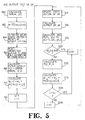
- FIG. 5 provides a flow chart for implementing the present invention into microprocessor form.
- microprocessors include internal memory which will be referred to in the description of a flow chart of Figure 5.
- step 180 wherein the input signal power (p) is determined and the response (d j ) of the desired filter (DF) to the input signal is calculated. This value (d j ) is the output of the desired filter characteristic.
- step 182 the value of ⁇ is determined and is equal to 1 divided by N+1 times the signal power determined in 180 and wherein N is equal to the number of sections of the adaptive digital filter.
- step 184 the value of the output (d j ) of the desired filter (DF) and the initial adaptive filter state vector are stored in memory and the initial adaptive filter coefficient vector is set to zero.
- step 186 parameter buffer, or memory, is set to zero so that all of the variables such as the gradients are set to zero and the desired number of iterations is stored in memory.
- step 188 the output of the adaptive filter y(j) and the error signal are determined.
- step 190 the first adaptive filter coefficient update is performed utilizing the expression indicated.
- step 192 the iteration number is set to one.
- step 194 the adaptive filter state vector is updated and in step 196, the output of the adaptive filter is calculated.
- step 198 the error signal e(j) is calculated and the gradient for the first iteration is calculated and stored in memory as the gradient of the last iteration. The gradient for the current iteration is then calculated.
- step 200 the error signal is compared to the predetermined standard. If the error signal is less than the predetermined standard, then the iterative process is stopped. If the error signal is not less than the predetermined standard then the process continues to step 202 wherein the values of R g (j), ⁇ and ⁇ are calculated using the expressions previously described.
- step 204 the new adaptive filter coefficient is determined by utilizing the stochastic average of the gradients generated.
- step 206 it is determined if the number of iterations now exceed the maximum number of iterations. If the answer is "Yes”, then the iteration process is stopped. If the answer is "No", then the iterative number is update by one in step 208, and the process returns to update the memory which contains the new filter coefficient. As a result, the new filter coefficient is available for the subsequent iterative process.
- the present invention provides a new and improved system and method for generating coefficients for use in a digital filter.
- the system and method of the present invention utilizes an iterative adaptive process which includes a least mean square process and wherein the updated values for the filter coefficients are based upon the stochastic average of the gradients generated during previous iterations.
- the foregoing results in a system and method for generating coefficients for use in a digital filter which is insensitive to noise in the gradient estimate and which has a fast convergence without having to use an optimal step-size.
- the system utilizes a 1-pole correlator to estimate the correlation between the adaptive error and the signal. The correlator is used for fast, efficient gradient estimation rather than to control the step-size as in prior art processes.
Landscapes
- Filters That Use Time-Delay Elements (AREA)
- Compositions Of Oxide Ceramics (AREA)
- Signal Processing For Digital Recording And Reproducing (AREA)
- Developing Agents For Electrophotography (AREA)
Abstract
Description
- The present invention relates in general to a system and method for generating coefficients for digital filters. The present invention more particularly relates to such a system and method wherein an iterative adaptive process is utilized which employs a least mean square processor with the step size of the filter coefficients in process being related to the stochastic average of the gradients generated during the iterative process.
- Digital filters find application in digital circuits, including those implemented in integrated circuit form. Such filters exhibit many advantages such as, for example, high reliability, no drift with time, no drift with temperature, unit-to-unit repeatability, and superior transmission performance. Digital filters can include one or more sections, the number of sections depending mainly upon the desired accuracy in realizing the nominal characteristics of the filter. In other words, an increase in the number of sections a digital filter provides a corresponding increase in the accuracy to which the desired filter characteristics can be obtained.
- One application for digital filters is in a subscriber line audio-processing circuit (SLAC). SLAC devices are utilized in telephone systems to perform CODEC and filter functions associated with the two-wire section of the subscriber line circuiting in a digital switch. To that end, these circuits provide conversion of analog voice signals to digital pulse code modulated (PCM) samples for placement of the PCM signals onto a PCM highway, and conversion of digital PCM signals received from the PCM highway into analog voice signals. During this conversion process, digital filters are used to band-limit the voice signals, set gain, perform trans-hybrid balancing, provide adjustment of termination impedance, and provide frequency attenuation adjustment (equalization) of the receive and transmit paths.
- To implement a digital filter, it is necessary to provide a filter coefficient for each section or tap of the filter. This is generally accomplished by storing the filter coefficient in a memory of the device employing the filter. The filter coefficient for each filter section is transformed from a single number into a plurality of coefficients known as Canonic Signed Digit (CSD) coefficients before storage into memory. CSD coefficients and the manner in which they may be derived from a single coefficient are well known in the art.
- In the prior art, the coefficients for the digital filter section (before conversion into CSD coefficients) were generated by an adaptive iterative least mean square process. During this prior art process, the coefficients of the filter section have been, during each iteration, updated from the last iteration by the instantaneous gradient value. In such a process, the instantaneous gradient, based upon a single sample, is the product of the instantaneous value of a time-varying input signal and the simultaneous instantaneous value of an error signal. The error signal is generated by applying the input signal to both a desired filter characteristic and the filter coefficients in process to generate first and second outputs, and then generating the difference between these output. When the error signal is detected to be below a predetermined standard, the process is stopped and the last set of coefficients used in the process are the final coefficients to be used in the filter after conversion to the CSD format.
- While the aforementioned iterative process has been adequate in its use to determine digital filter coefficients, there remains the need for improvement in such processes. More particularly, the prior art least mean square iterative process is not computationally efficient and reasonably fast in convergence unless an optimal step-size is used in a noise-free environment. Unfortunately, it is difficult to find the optimal step-size that satisfies both requirements of fast tracking capability during an adaptive process and small misadjustment error after convergence.
- In addition, the foregoing process is sensitive to noise in generating the gradient because the gradient is based upon a single time sample. Hence in practice, the prior art iterative process has required considerable time for completion to arrive at an accurate determination of digital filter coefficients given the fact that it is sensitive to noise and the variable optimum step-size is difficult to determine.
- In 1989 IEEE International Symposium on Circuits and Systems; Portland, 8-11 May 1989; pages 1752-1757 G.K. Boray et al: "Conjugate Gradient Techniques for Adaptive Filtering" there is described a conjugate gradient method for updating the adaptive filter coefficients in a digital filter wherein the gradient estimate is obtained by averaging the instantaneous gradient estimates over a specified number or "window" of past values.
- In IEEE Acoustic, Speech and Signal Processing Magazine. Vol 37, No. 2, February 1989 pages 254-264; Yung-Fu Chen et al: "Analysis of an Adaptive Technique for Modelling Sparse Systems" there is described an adaptive delay filter that includes adaptive gains in addition to variable delay taps. Algorithms are developed for determining the delay taps and their corresponding gains are then adapted for the adaptive delay filter.
- According to the present invention there is provided a system for generating coefficients for use in a digital filter, the system comprising: means for providing data indicative of a desired filter characteristic; iterative processing means for generating at least one filter coefficient and a gradient for each said iteration, said iterative processing means including means for generating a time-varying gradient estimate and means for varying said at least one coefficient during each said iteration by an amount related to the generated gradient estimate; comparing means for comparing said at least one generated coefficient to said desired filter characteristic; and means for terminating said iterative processing means when said at least one coefficient is within a given range of said desired filter characteristic, characterised in that the means for generating the time-varying gradient estimate generates the estimate in accordance with the stochastic average of the previously generated gradients such that the average is taken over a progressively increasing number of past values as the iteration process approaches convergence.
- Since the instantaneous estimates are averaged over a greater number of past values as the process approaches convergence, the system is more reliable and more immune to noise at or near convergence compared to a system in which the instantaneous estimates are averaged over a fixed predetermined number of past values.
- In a preferred embodiment of the invention the iterative processing means include means for generating a pair of stochastic averaging coefficients for generating the stochastic average of the gradients. The two coefficients may comprise an adaptive gain factor and an adaptive forgetting factor, and the means for varying the filter coefficient in each iteration may then include a correlator circuit having a first amplifier with a gain equal to the adaptive gain factor and a second amplifier having a gain equal to the forgetting factor.
- Accordingly, there is described herein a new and improved system and method for generating digital filter coefficients.
- There is further described such a system and method which is insensitive to noise and wherein the optimum step-size is readily determined.
- There is further described such a system and method wherein the step-size is related to the stochastic average of the gradients generated during the adaptive process.
- Two embodiments of the present invention will now be described, by way of example only, with reference to the accompanying drawings, in the several figures of which like reference numerals identify identical elements, and wherein:
- Figure 1 is a block diagram of the signal processing circuitry of a subscriber line audio-processing circuit which includes digital filters, the coefficients of which, may be generated by a system and method embodying the present invention;
- Figure 2 is an overall system block diagram embodying the present invention;
- Figure 3 is a schematic circuit diagram illustrating the manner in which the present invention may be implemented in hardware form in accordance with a first embodiment of the present invention;
- Figure 4 is a schematic circuit diagram illustrating the manner in which the present invention may be implemented in hardware form in accordance with a second embodiment of the present invention; and
- Figure 5 is a flow chart illustrating the manner in which the present invention may be implemented in microprocessor form in accordance with the first embodiment of the present invention.
- Referring now to Figure 1, it illustrates, in block diagram form, the signal processing circuitry of a subscriber line audio-processing circuit in which the present invention may be utilized to an advantage. The subscriber line audio-processing circuit (SLAC) performs the CODEC and filter functions associated with the two-wire section of the subscriber line circuitry in a digital switch. In general, these functions involve converting an analog voice signal into digital pulse code modulated (PCM) samples for placing the PCM samples onto a PCM highway and converting digital PCM samples received from the PCM highway into an analog signal.
- The
circuit 10 of Figure 1 generally includes afirst input 12 for receiving analog voice signals, a first output 14 for transferring the PCM samples to a time slot assigning circuit for placement of the PCM samples onto the PCM highway, asecond input 16 adapted to be coupled to the time slot assigning circuit for receiving PCM samples from the PCM highway, and asecond output 18 for providing analog signals representative of the PCM samples received from the PCM highway. The signal processing circuitry extending between thefirst input 12 and the first output 14 represents the transmit signal processing path of the circuit and the signal processing circuitry from thesecond input 16 to thesecond output 18 represents the receive signal processing path of the circuit. - The transmit signal processing path includes an
amplifier 20, an analog-to-digital converter 22, afirst decimator 24, asecond decimator 26, anattenuator 28, a first programmable digital filter (X) 30, a high-pass filter 32, and a data compressor 34. Theamplifier 20 is an analog amplifier and provides analog signal gain into the analog-to-digital converter 22. The analog-to-digital converter 22 converts the analog voice signals to PCM data samples. Thedecimators attenuator 28 provides signal level correction into thefilter 30. Thefilter 30 is, for example, a six-tapp finite input response filter which provides frequency response correction. The high-pass filter 32 rejects low frequencies such as frequencies in the range of 50 hz or 60 hz for the purpose of filtering, for example, AC line noise. Lastly, the compressor 34 compresses the digital PCM samples in a known manner. - The receive signal processing circuitry includes an expander 40, a low-pass filter 42, a second programmable digital filter (R) 44, an attenuator 46,
interpolators programmable filter 44 is preferably a 6-tap finite input response filter which operates at a 16 khz sampling rate and provides frequency response correction. The attenuator 46 provides signal amplitude scaling into theinterpolators interpolators output terminal 18. - Coupled across the transmit and receive processing paths is a third programmable filter (Z) 56.
Filter 56 provides feedback from the transmit signal path to the receive signal path to modify the effective input impedance into the system. Hence,filter 56 provides impedance matching to assure efficient signal transfer. Also coupled across the receive and transmit signal processing path is a fourth programmable filter (B) 58.Filter 58 includes a single-pole infinite impulse response filter section 58a and 8-tap finite input response filter section 58b.Filter 58 provides trans-hybrid balance between the receive and transmit signal processing circuits to eliminate echo within the system. - The
programmable filters - Referring now to Figure 2, it illustrates a system embodying the present invention for generating the coefficients of digital filters, such as
filters system 60 generally includes a desired filtercharacteristic processor 62 and anadaptive coefficient processor 64. The adaptive coefficient processor is arranged to provide the final filter coefficients to a CSD converter 66 for converting the filter coefficients into the CSD format. The CSD converter 66 is coupled to afilter memory 68 for storing the CSD formatted filter coefficients into the memory of the subscriber line audio-processing circuit. - The desired filter characteristic processor preferably takes the form of an IBM compatible computer operating under a commercially available software program referred to as AmSLAC-II available from Advanced Micro Devices, Inc. of Sunnyvale, California, and is disclosed in the AMSLAC-II Technical Manual (Order No. 10249 A). The desired filter characteristic processor having this configuration provides a desired filter characteristic in response to inputted input information such as line impedance, desired terminating impedance, the actual terminating impedance at the exchange, the attenuation of attenuator 46 of Figure 1, the desired gain of
attenuator 28, the receive buffer transfer function, the transmit buffer transfer function, fuse resistances, and the two-wire return loss. In response to this information, the desired filter characteristic processor models the subscriber line audio-processing circuit to provide the desired filter characteristic for each of the programmable filters. The aforementioned input information is inputted into the desired filter character processor atinputs - The desired filter
characteristic processor 62 includes afurther input 78 for receiving a time-varying input signal X(j). After applying the desired filter characteristic to the input signal, theprocessor 62 provides the resulting output at anoutput 80. The resulting output of applying the desired filter characteristic to the input signal is identified as d(j). - The
adaptive coefficient processor 64, as will be seen subsequently with reference to Figures 3 through 5, performs an iterative least means square process for generating the digital filter coefficients. Unlike the prior art least means square process however, wherein the coefficient step-size was determined by the instantaneous value of the iterative gradient, the adaptive coefficient processor of the present invention generates the adaptive coefficient step-size in accordance with the stochastic average of the iterative gradients. Because the step-sizes are the result of the stochastic average of the gradients, the step-sizes are not dependant upon the instantaneous value of the gradients so that the iterative process which results is insensitive to noise in the gradient estimate and fast in convergence without having to use an optimal step-size. Thus, while the least mean square process estimates its gradient on a sample-by-sample basis, the least means square process of the instant invention which utilizes stochastic averaging in estimating its gradient provides an estimate of the correlation between the adaptive error and the input signal. - In accordance with the present invention, the filter coefficients are updated according to the following formula:

- G(j) is given by the expression below.

- G(j) is the time-varying gradient vector estimate obtained by estimating the cross-correlation between the adaptive error signal, e(j), and the system input signal, X(j), i.e.

- The α(j) and β(j), are respectively, an adaptive gain factor and an adaptive forgetting factor.
- In the iterative process of the present invention, as the process converges, the adaptive error is initially large and highly non-stationary and the cross-correlation between the adaptive error and system input signals yields a large gradient estimate and hence provides fast convergence. After convergence, the adaptive error is small, almost random and stationary, and the cross-correlation yields a small gradient estimate and hence a small misadjustment error with fine tracking. Therefore, since the iterative process of the present invention automatically adjusts the time-varying gradient estimate according to the gradient of the adaptive error surface it ensures that convergence is always in the optimal way.
- As will be seen hereinafter with respect to Figures 3 and 4, an iterative processing circuit is provided which includes an adaptive 1-pole correlator which provides an output signal which is the time-varying gradient estimate given below.

- For each of the foregoing expressions, it should be kept in mind that these expressions relate to digital operations where a "j" relates to a value taken during a current time period and wherein a "j-1" relates to a value taken during a previous time interval. In the expression immediately above, the adaptive gain, α(j) is used for rapid tracking capability and stability, and the adaptive forgetting factor β(j) is used to maximize the averaging effect (for insensitivity to gradient estimation noise) for given error statistics, to yield a small misadjustment error.
- The adaptive forgetting factor β(j) is 1- the estimate of the normalized autocorrelation of the gradient estimate, and is given below.

- The estimate of the normalized autocorrelation of the gradient estimate, or Rg(j) is given below.

where,
- The 1-pole correlator referred to previously for implementing the present invention has the following transfer function.

- The forgetting factor, β(j) is obtained from the expression above of 1- the estimate of the normalized autocorrelation of the gradient estimate, and the adaptive gain α(j) is obtained so as to keep the dc gain less than 1.0 for stability. In other words, the following expression must be adhered to.

- In general, the larger the value of gamma used, the faster the convergence.
- As can been seen from the foregoing, during the iterative process, and more particularly at the end of each iteration, the adaptive coefficient processor generates two filter coefficients (β,α) related to the stochastic average of the gradients generated by the system. As can also be noted in Figure 2, the adaptive coefficient processor is coupled to the input signal X(j). Before a new set of filter coefficients is generated, the input signal is applied to the coefficients in the adaptive coefficient processor to provide a second output signal resulting from the application of the set of filter coefficients to the input signal. A combining circuit within the adaptive coefficient processor then combines the output d(j) of the desired filter characteristic processor with the second output signal generated by the adaptive coefficient processor to develop the error signal e(j). The error signal is then multiplied by the input signal from which it resulted to derive a new gradient which is then utilized for generating a new stochastic average of the gradients which in turn is used for generating a new set of filter coefficients. At the end of each iteration, the error signal is compared to a predetermined standard. If the error signal is less than a predetermined standard, the iterative process is stopped and the set of coefficients used in the last iteration are the final coefficients for the digital filter. Hence, at the end of each iteration, through this process, generated filter coefficients are compared to the desired filter characteristic and, if the filter coefficients are within a given range of the desired filter characteristic, the iterative process is stopped and the present set of generated filter coefficients represent the final filter coefficients for the digital filter.
- When the iterative process is completed, the final set of generated filter coefficients is transferred to the CSD converter which converts the coefficients to the Canonic Signed Digit format. After being so converted, the coefficients in the CSD format are transferred to the filter memory of the subscriber line audio-processing circuit. Such memory may be in the form of a random access memory (RAM) .
- Referring now to Figure 3, Figure 3 illustrates in hardware circuit diagram form an adaptive coefficient processor 64a structured in accordance with a first embodiment of the present invention in conjunction with the desired filter
characteristic processor 62 as previously described. - The adaptive coefficient processor generally includes a plurality of filter
coefficient generating circuit 82a, 82b through 82n. In practice, one such filter coefficient circuit is provided for each section of the digital filter for each the coefficients are to be generated. In other words, if the digital filter includes six sections, then there would be six filter coefficient generating circuits provided. - The adaptive coefficient processor also includes circuits for generating the pair of stochastic averaging coefficients, namely β, the adaptive forgetting factor, and α, the adaptive gain. That circuit is identified by
reference character 84. The adaptive coefficient processor 64a further includes a combiningcircuit 86, a comparecircuit 88, and amultiplication circuit 90. The adaptive coefficient processor includes aninput 92 which is coupled to the input means 94 of the system for receiving the time-varying input signal. - The filter coefficient generating circuit 82a includes a 1-
pole correlator 96 comprising a summing circuit 98, anamplifier 100 having a gain equal to the adaptive gain, a delay network 102, and another amplifier 104 having a gain equal to the forgetting factor. - The filter coefficient generating circuit 82a further includes a multiplying circuit 106 which multiplies the results of the 1-pole correlator with a stability factor µ which is a step-size. The filter coefficient generating circuit 82a further includes a summing
circuit 108 and adelay network 110. Each of the delay networks illustrated in Figure 3 is a delay network which delays signals applied at its input by one time period. Each of thecoefficient generating circuits 82b through 82n are identical to circuit 82a and therefore, only circuit 82a has been shown in detail herein. - The 1-
pole correlator circuit 96 implements the generation of the amount by which the coefficients are to be varied in accordance with the stochastic average of the previously generated gradients and the summingcircuit 108 adds that amount to the previous coefficient for generating the new coefficient during the next iteration. The gain values for theamplifiers 100 and 104 are obtained from thecircuit 84 which generates the pair of stochastic averaging coefficients β and α. - The
circuit 84 includesdelay networks multipliers amplifiers root circuit 142. Thecircuit 84 further includes summingcircuits 144 and 146. - The delay network 120, multiplier 128, amplifier 134, summing
circuit 144,amplifier 140, and delay network 122 provide or generate the numerator for the expression given above for Rg(j). Thecomponents including multiplier 130, amplifier 136, summer 146, andamplifier 138,delay networks multiplier 132 and the square-root circuit 142 provide the denominator for the value of Rg(j). A dividingcircuit 148 divides the numerator by the denominator to provide the value of Rg(j). - A
subtractor circuit 150 subtracts the value of Rg(j) from one to provide the value of β which is used to set the gain of amplifier 104. Acircuit 152 provides the value of α as illustrated which is used to set the gain ofamplifier 100. This process is performed during each iteration for the purpose of updating the stochastic average of the previously generated gradients. Also, the same values for β and α are used in connection with each of the other filtercoefficient generating circuits 82b through 82n. - As can be noted from the Figure, a
delay network 154 is coupled between theinput 92 and amultiplier 156, and this kind of structure is completed for each coefficient generating circuit. This permits each coefficient to act upon the input signal and the individual results of the each of the coefficients is summed by a summingcircuit 160 to provide the resulting output y(j) which results from the filter coefficients process acting upon the signal. As can be noted, the signal y(j) is coupled to the negative input of thesummer 86 and the output of the desired filtercharacteristic processor 62, d(j), is coupled to a positive input of thesummer 86. As a result, these two signals are combined to produce the error signal e(j). The error signal is applied to an input of the comparecircuit 88 and is compared to a threshold or a predetermined standard 162 applied to the other input of the comparecircuit 88. If the error signal is greater than the predetermined standard, the error signal is conveyed through the comparecircuit 88 to themultiplier 90 for purposes of generating the new gradient for the next iteration. If the error signal is less than the predetermined standard, the error signal is not conveyed by the compare circuit to stop the iterative process. When the iterative process is completed, the filter coefficients currently at the inputs to themultipliers 156 are the final filter coefficients for the digital filter. - Hence, during each iteration, the adaptive coefficient processor 64a through the circuits 82a through 82n generate a new set of filter coefficients which are updated from the last value of the filter coefficients by an amount dependant upon the stochastic average of the previously generated gradients. In addition, the coefficients generated in each set of coefficients is equal to the number of filter sections of the digital filter.
- Referring now to Figure 4, it shows another adaptive coefficient processor structured in accordance with a second embodiment of the present invention. The processor 64b is similar to the processor 64a of Figure 3 and incorporates many of the same components which have been denoted by identical reference characters. However, the difference between the processor 64b and processor 64a is that the stochastic averaging coefficients β and α used in the processor 64b are the stochastic average of the coefficients β and α. To that end, the circuit 84b includes a first single-
pole correlator 170 and a second single-pole correlator 172.Correlator 170 includes anamplifier 174 and an amplifier 176 with the gain ofamplifier 174 equal to the α of the last time period and the gain of amplifier 176 being equal to the β of the last time period. Similarly, the correlator 172 includesamplifiers 178 and 180, wherein the gain of amplifier 178 is the α of the last time period and the gain ofamplifier 180 is the β of the last time period. Hence, resulting values of β and α generated by the circuit 84b represent the stochastic average of the generated and stochastic averaging coefficients. - In the adaptive coefficient processor 64b, since values of β and α are now the stochastic averages of those coefficients, the iterative process will converge at a faster rate than the iterative process of processor 64a of Figure 3. The reason for this is that values of β and α are now time-dependant and signal-dependent. In all other respects, the processor 64b operates in the same manner of processor 64a of Figure 3.
- Referring now to Figure 5, it provides a flow chart for implementing the present invention into microprocessor form. Such microprocessors include internal memory which will be referred to in the description of a flow chart of Figure 5.
- In the microprocessor implementation of the present invention, a series of calculations must be performed before the iterative process begins. These steps include
step 180 wherein the input signal power (p) is determined and the response (dj) of the desired filter (DF) to the input signal is calculated. This value (dj) is the output of the desired filter characteristic. - In
step 182, the value of µ is determined and is equal to 1 divided by N+1 times the signal power determined in 180 and wherein N is equal to the number of sections of the adaptive digital filter. In the next step 184 the value of the output (dj) of the desired filter (DF) and the initial adaptive filter state vector are stored in memory and the initial adaptive filter coefficient vector is set to zero. - In step 186, parameter buffer, or memory, is set to zero so that all of the variables such as the gradients are set to zero and the desired number of iterations is stored in memory. In
step 188, the output of the adaptive filter y(j) and the error signal are determined. In thenext step 190, the first adaptive filter coefficient update is performed utilizing the expression indicated. In thenext step 192, the iteration number is set to one. - In
step 194, the adaptive filter state vector is updated and instep 196, the output of the adaptive filter is calculated. Instep 198, the error signal e(j) is calculated and the gradient for the first iteration is calculated and stored in memory as the gradient of the last iteration. The gradient for the current iteration is then calculated. - In
step 200, the error signal is compared to the predetermined standard. If the error signal is less than the predetermined standard, then the iterative process is stopped. If the error signal is not less than the predetermined standard then the process continues to step 202 wherein the values of Rg(j), β and α are calculated using the expressions previously described. Instep 204, the new adaptive filter coefficient is determined by utilizing the stochastic average of the gradients generated. In thenext step 206, it is determined if the number of iterations now exceed the maximum number of iterations. If the answer is "Yes", then the iteration process is stopped. If the answer is "No", then the iterative number is update by one instep 208, and the process returns to update the memory which contains the new filter coefficient. As a result, the new filter coefficient is available for the subsequent iterative process. - The foregoing continues until the error signal is less than the predetermined standard. When the error signal is less than the predetermined standard, the iterative process is stopped and the filter coefficient value used in the last iteration is utilized as the final coefficient value for the digital filter.
- From the foregoing, it can be seen that the present invention provides a new and improved system and method for generating coefficients for use in a digital filter. The system and method of the present invention utilizes an iterative adaptive process which includes a least mean square process and wherein the updated values for the filter coefficients are based upon the stochastic average of the gradients generated during previous iterations. The foregoing results in a system and method for generating coefficients for use in a digital filter which is insensitive to noise in the gradient estimate and which has a fast convergence without having to use an optimal step-size. In accordance with the present invention, the system utilizes a 1-pole correlator to estimate the correlation between the adaptive error and the signal. The correlator is used for fast, efficient gradient estimation rather than to control the step-size as in prior art processes.
Claims (13)
- A system for generating coefficients for use in a digital filter, said system comprising:
means (62) for providing data indicative of a desired filter characteristic;
iterative processing means (64) for generating at least one filter coefficient and a gradient for each said iteration, said iterative processing means including means (96) for generating a time-varying gradient estimate and means (82) for varying said at least one coefficient during each said iteration by an amount related to the generated gradient estimate;
comparing means (86) for comparing said at least one generated coefficient to said desired filter characteristic; and
means (88) for terminating said iterative processing means when said at least one coefficient is within a given range of said desired filter characteristic,
characterised in that the means (96) for generating the time-varying gradient estimate generates the estimate in accordance with the stochastic average of the previously generated gradients such that the average is taken over a progressively increasing number of past values as the iteration process approaches convergence. - A system as defined in claim 1 wherein said iterative processing means (64) includes means (84) for generating a pair of stochastic averaging coefficients from which said stochastic average of said gradients is generated.
- A system as defined in claim 2 wherein said pair of stochastic averaging coefficients are generated in response to the stochastic average of the previously generated stochastic averaging coefficients.
- A system as defined in claim 2 or claim 3 wherein a time-varying input signal is applied to said means (62) providing the desired filter characteristic and to said iterative processing means (64) to generate first and second outputs respectively, and wherein said first and second outputs are combined to generate an error signal, said iterative processing means being terminated by said terminating means (88) when said error signal is less than a predetermined standard.
- A system according to claim 4 further comprising means for generating an estimate Rg(j) of the normalized autocorrelation of the gradient estimate, and wherein a first of the averaging coefficients is an adaptive forgetting factor β(j) given by the expression β(j) = 1 - Rg(j).
- A system according to claim 5 wherein the second averaging coefficient is an adaptive gain factor α(j) and the gradient estimate g(j) is given by the expression

- A system according to claim 6 wherein the said means (82) for varying the filter coefficient in each iteration includes a correlator circuit (96) having a first amplifier (100) with a gain equal to the adaptive gain factor α(j) and a second amplifier (104) having a gain equal to the forgetting factor β(j).
- A method for generating coefficients for use in a digital filter, said method comprising the steps of:
providing a desired filter characteristic;
iteratively generating at least one filter coefficient and a gradient estimate for each iteration by varying the at least one coefficient during each said iteration by an amount related to the generated gradient estimate;
comparing the at least one generated coefficient to the desired filter characteristic; and
terminating the iterative generation of said at least one coefficient when the coefficient is within a given range of said desired filter characteristic, characterised in that the time-varying gradient estimate is generated in accordance with the stochastic average of the previously generated gradients such that the average is taken over a progressively increasing number of past values as the iteration process moves toward convergence. - A method as defined in claim 8 wherein said at least one coefficient is compared to said desired filter characteristic by applying a time-varying signal to said desired filter characteristic and said at least one generated coefficient and comparing the outputs thereof to generate an error signal.
- A method as defined in claim 9 wherein said comparing step includes summing the positive result of said desired filter coefficient acting upon said time varying signal with the negative result of said at least one generated coefficient acting upon said time-varying signal to generate said error signal during each iteration.
- A method as defined in claim 10 wherein said iterative generation of said at least one coefficient is terminated when said error signal is less than a predetermined standard.
- A method as defined in any one of the claims 7-11 including the further step of generating a pair of stochastic averaging coefficients for generating said stochastic average of said gradients.
- A method as defined in claim 12 wherein said step of generating said pair of stochastic averaging coefficients includes generating said pair of stochastic averaging coefficients from the stochastic average of said stochastic averaging coefficients.
Applications Claiming Priority (2)
| Application Number | Priority Date | Filing Date | Title |
|---|---|---|---|
| US359022 | 1989-05-30 | ||
| US07/359,022 US5058047A (en) | 1989-05-30 | 1989-05-30 | System and method for providing digital filter coefficients |
Publications (3)
| Publication Number | Publication Date |
|---|---|
| EP0400850A2 EP0400850A2 (en) | 1990-12-05 |
| EP0400850A3 EP0400850A3 (en) | 1991-11-27 |
| EP0400850B1 true EP0400850B1 (en) | 1995-11-22 |
Family
ID=23411995
Family Applications (1)
| Application Number | Title | Priority Date | Filing Date |
|---|---|---|---|
| EP90305400A Expired - Lifetime EP0400850B1 (en) | 1989-05-30 | 1990-05-18 | Generating coefficients for digital filters |
Country Status (5)
| Country | Link |
|---|---|
| US (1) | US5058047A (en) |
| EP (1) | EP0400850B1 (en) |
| JP (1) | JP3250801B2 (en) |
| AT (1) | ATE130708T1 (en) |
| DE (1) | DE69023697T2 (en) |
Cited By (1)
| Publication number | Priority date | Publication date | Assignee | Title |
|---|---|---|---|---|
| DE102008026518A1 (en) | 2008-04-28 | 2009-11-19 | Rohde & Schwarz Gmbh & Co. Kg | Automatic computer-based digital filter i.e. low pass filter, coefficients determining method for signal processing device, involves uniquely determining coefficients of digital filter from predetermined and non-predetermined input vectors |
Families Citing this family (43)
| Publication number | Priority date | Publication date | Assignee | Title |
|---|---|---|---|---|
| JP3038790B2 (en) * | 1990-04-27 | 2000-05-08 | 日本電気株式会社 | Equalizer |
| US5272656A (en) * | 1990-09-21 | 1993-12-21 | Cambridge Signal Technologies, Inc. | System and method of producing adaptive FIR digital filter with non-linear frequency resolution |
| WO1992005501A1 (en) * | 1990-09-21 | 1992-04-02 | Cambridge Signal Technologies, Inc. | System and method of producing adaptive fir digital filter with non-linear frequency resolution |
| FR2670600B1 (en) * | 1990-12-14 | 1993-02-12 | Thomson Csf | METHOD AND DEVICE FOR DETECTING CHANGES IN SPEAKING SIGNAL CHARACTERISTICS APPLIED TO LOW FLOW VOCODERS. |
| JP2842026B2 (en) * | 1991-02-20 | 1998-12-24 | 日本電気株式会社 | Adaptive filter coefficient control method and apparatus |
| US5136531A (en) * | 1991-08-05 | 1992-08-04 | Motorola, Inc. | Method and apparatus for detecting a wideband tone |
| US5282154A (en) * | 1992-06-01 | 1994-01-25 | Thomson Consumer Electronics, Inc. | System for determining and repairing instability in an IIR filter suitable for use in deghosting apparatus |
| US5828700A (en) * | 1993-08-05 | 1998-10-27 | Micro Linear Corporation | Adaptive equalizer circuit |
| KR100248266B1 (en) * | 1994-03-07 | 2000-03-15 | 김영환 | Tap coefficient updating device of finite shock response adaptive digital filter |
| JPH07248778A (en) * | 1994-03-09 | 1995-09-26 | Fujitsu Ltd | Adaptive filter coefficient updating method |
| US5532950A (en) * | 1994-04-25 | 1996-07-02 | Wadia Digital Corporation | Dynamic digital filter using neural networks |
| US5426597A (en) * | 1994-04-26 | 1995-06-20 | The United States Of America As Represented By The Secretary Of The Navy | Adaptive infinite impulse response (IIR) filter system |
| US5627896A (en) * | 1994-06-18 | 1997-05-06 | Lord Corporation | Active control of noise and vibration |
| US5682341A (en) * | 1995-04-19 | 1997-10-28 | Korea Advanced Institute Of Science And Technology | Adaptive signal processor using Newton/LMS algorithm |
| US5844941A (en) * | 1995-07-20 | 1998-12-01 | Micro Linear Corporation | Parallel adaptive equalizer circuit |
| KR100248021B1 (en) * | 1995-09-30 | 2000-03-15 | 윤종용 | Method and circuit of signal processing of csd filter |
| JPH09270672A (en) * | 1996-03-29 | 1997-10-14 | Sharp Corp | Adaptive digital filter device |
| US6011813A (en) * | 1997-06-23 | 2000-01-04 | Philips Electronics North America Corporation | Blind equalization method and apparatus having reduced complexity |
| US6757326B1 (en) * | 1998-12-28 | 2004-06-29 | Motorola, Inc. | Method and apparatus for implementing wavelet filters in a digital system |
| US7639744B1 (en) * | 1999-06-25 | 2009-12-29 | Infineon Technologies Ag | Programmable digital bandpass filter for a codec circuit |
| KR100330237B1 (en) * | 1999-07-19 | 2002-03-25 | 윤종용 | apparatus and method for estimating an echo path delay |
| US7072392B2 (en) * | 2000-11-13 | 2006-07-04 | Micronas Semiconductors, Inc. | Equalizer for time domain signal processing |
| US6829297B2 (en) * | 2001-06-06 | 2004-12-07 | Micronas Semiconductors, Inc. | Adaptive equalizer having a variable step size influenced by output from a trellis decoder |
| US7190744B2 (en) * | 2001-06-07 | 2007-03-13 | Micronas Semiconductors, Inc. | Error generation for adaptive equalizer |
| US7418034B2 (en) * | 2001-06-19 | 2008-08-26 | Micronas Semiconductors. Inc. | Combined trellis decoder and decision feedback equalizer |
| KR100422449B1 (en) * | 2001-11-12 | 2004-03-11 | 삼성전자주식회사 | Low power CSD Linear phase FIR filter architecture using vertical common subexpression and filter design method therefore |
| US7321642B2 (en) * | 2002-04-05 | 2008-01-22 | Micronas Semiconductors, Inc. | Synchronization symbol re-insertion for a decision feedback equalizer combined with a trellis decoder |
| US6995617B2 (en) * | 2002-04-05 | 2006-02-07 | Micronas Semiconductors, Inc. | Data-directed frequency-and-phase lock loop |
| US7272203B2 (en) * | 2002-04-05 | 2007-09-18 | Micronas Semiconductors, Inc. | Data-directed frequency-and-phase lock loop for decoding an offset-QAM modulated signal having a pilot |
| US7376181B2 (en) * | 2002-04-05 | 2008-05-20 | Micronas Semiconductors, Inc. | Transposed structure for a decision feedback equalizer combined with a trellis decoder |
| US7200552B2 (en) * | 2002-04-29 | 2007-04-03 | Ntt Docomo, Inc. | Gradient descent optimization of linear prediction coefficients for speech coders |
| US6774822B1 (en) * | 2003-01-09 | 2004-08-10 | Process Control Corporation | Method and systems for filtering unwanted noise in a material metering machine |
| US7904496B2 (en) * | 2006-01-24 | 2011-03-08 | Texas Instruments Incorporated | Method and system for selecting effective tap values for a digital filter |
| US8284870B1 (en) | 2006-02-07 | 2012-10-09 | Link—A—Media Devices Corporation | Timing loop |
| US7917563B1 (en) * | 2006-02-07 | 2011-03-29 | Link—A—Media Devices Corporation | Read channel processor |
| US7746924B2 (en) * | 2006-05-09 | 2010-06-29 | Hewlett-Packard Development Company, L.P. | Determination of filter weights |
| EP1976122A1 (en) * | 2007-03-31 | 2008-10-01 | Sony Deutschland Gmbh | Adaptive filter device |
| GB0709074D0 (en) * | 2007-05-11 | 2007-06-20 | Ip Access Ltd | Design method for root raised cosine filter |
| KR101677294B1 (en) * | 2010-04-19 | 2016-11-18 | 삼성전자주식회사 | Smoothing apparatus for peak windowing |
| GB2488599B (en) * | 2011-03-04 | 2017-11-29 | Snell Advanced Media Ltd | Adaptive signal processing |
| US9414372B2 (en) * | 2012-03-16 | 2016-08-09 | Qualcomm Incorporated | Digital filter control for filter tracking speedup |
| EP3301810B1 (en) * | 2016-09-29 | 2019-02-13 | Intel IP Corporation | Adaptive filter circuits and methods |
| CN107659290B (en) * | 2017-08-09 | 2021-02-09 | 湖南艾科诺维科技有限公司 | Bandwidth extension filter and design method thereof |
Family Cites Families (3)
| Publication number | Priority date | Publication date | Assignee | Title |
|---|---|---|---|---|
| NL7905577A (en) * | 1979-07-18 | 1981-01-20 | Philips Nv | DEVICE WITH A NON-RECURRENCE FILTER. |
| US4791390A (en) * | 1982-07-01 | 1988-12-13 | Sperry Corporation | MSE variable step adaptive filter |
| FR2556530B1 (en) * | 1983-10-28 | 1986-04-04 | Telediffusion Fse | ECHO CORRECTION DEVICE, ESPECIALLY FOR A DATA BROADCASTING SYSTEM |
-
1989
- 1989-05-30 US US07/359,022 patent/US5058047A/en not_active Expired - Lifetime
-
1990
- 1990-05-18 AT AT90305400T patent/ATE130708T1/en not_active IP Right Cessation
- 1990-05-18 DE DE69023697T patent/DE69023697T2/en not_active Expired - Fee Related
- 1990-05-18 EP EP90305400A patent/EP0400850B1/en not_active Expired - Lifetime
- 1990-05-30 JP JP14324590A patent/JP3250801B2/en not_active Expired - Lifetime
Cited By (1)
| Publication number | Priority date | Publication date | Assignee | Title |
|---|---|---|---|---|
| DE102008026518A1 (en) | 2008-04-28 | 2009-11-19 | Rohde & Schwarz Gmbh & Co. Kg | Automatic computer-based digital filter i.e. low pass filter, coefficients determining method for signal processing device, involves uniquely determining coefficients of digital filter from predetermined and non-predetermined input vectors |
Also Published As
| Publication number | Publication date |
|---|---|
| US5058047A (en) | 1991-10-15 |
| JP3250801B2 (en) | 2002-01-28 |
| ATE130708T1 (en) | 1995-12-15 |
| EP0400850A3 (en) | 1991-11-27 |
| DE69023697T2 (en) | 1996-07-25 |
| DE69023697D1 (en) | 1996-01-04 |
| JPH0322704A (en) | 1991-01-31 |
| EP0400850A2 (en) | 1990-12-05 |
Similar Documents
| Publication | Publication Date | Title |
|---|---|---|
| US5058047A (en) | System and method for providing digital filter coefficients | |
| US5343522A (en) | Adaptive sparse echo canceller using a sub-rate filter for active tap selection | |
| KR100338656B1 (en) | Echo path delay estimation | |
| JP3216704B2 (en) | Adaptive array device | |
| US6097823A (en) | Digital hearing aid and method for feedback path modeling | |
| EP0221221B1 (en) | A process for determining an echo path flat delay and echo canceler using said process | |
| EP0500096B1 (en) | Method and apparatus for controlling coefficients of adaptive filter | |
| EP0561133B1 (en) | Multi-channel echo cancellation with adaptive filters having selectable coefficient vectors | |
| US5818945A (en) | Subband echo cancellation method using projection algorithm | |
| US4879745A (en) | Half-duplex speakerphone | |
| US5761638A (en) | Telephone network apparatus and method using echo delay and attenuation | |
| JP2625613B2 (en) | Adaptive echo cancellation method | |
| CA2171778A1 (en) | Method and apparatus for adaptive filtering | |
| RU2180984C2 (en) | Convergence measurement technique for adaptive filters | |
| US4811261A (en) | Adaptive digital filter for determining a transfer equation of an unknown system | |
| JP3068996B2 (en) | Adaptive filter device and method for generating step gain | |
| EP0114855B1 (en) | Adaptive filter update normalization | |
| US6950842B2 (en) | Echo canceller having an adaptive filter with a dynamically adjustable step size | |
| US4752903A (en) | Adaptive digital filter for eliminating howling | |
| JP2785858B2 (en) | Receiving method using high-speed adaptive filter | |
| US7050575B1 (en) | Echo canceler coefficient update apparatus and method | |
| EP0422809B1 (en) | Adaptive apparatus | |
| EP0286166B1 (en) | Arrangement for converting a first electric signal into a second electric signal | |
| JPH0253963B2 (en) | ||
| EP0715407B1 (en) | Method and apparatus for controlling coefficients of adaptive filter |
Legal Events
| Date | Code | Title | Description |
|---|---|---|---|
| PUAI | Public reference made under article 153(3) epc to a published international application that has entered the european phase |
Free format text: ORIGINAL CODE: 0009012 |
|
| AK | Designated contracting states |
Kind code of ref document: A2 Designated state(s): AT BE CH DE DK ES FR GB GR IT LI LU NL SE |
|
| PUAL | Search report despatched |
Free format text: ORIGINAL CODE: 0009013 |
|
| AK | Designated contracting states |
Kind code of ref document: A3 Designated state(s): AT BE CH DE DK ES FR GB GR IT LI LU NL SE |
|
| 17P | Request for examination filed |
Effective date: 19920507 |
|
| 17Q | First examination report despatched |
Effective date: 19940803 |
|
| GRAA | (expected) grant |
Free format text: ORIGINAL CODE: 0009210 |
|
| AK | Designated contracting states |
Kind code of ref document: B1 Designated state(s): AT BE CH DE DK ES FR GB GR IT LI LU NL SE |
|
| PG25 | Lapsed in a contracting state [announced via postgrant information from national office to epo] |
Ref country code: IT Free format text: LAPSE BECAUSE OF FAILURE TO SUBMIT A TRANSLATION OF THE DESCRIPTION OR TO PAY THE FEE WITHIN THE PRESCRIBED TIME-LIMIT;WARNING: LAPSES OF ITALIAN PATENTS WITH EFFECTIVE DATE BEFORE 2007 MAY HAVE OCCURRED AT ANY TIME BEFORE 2007. THE CORRECT EFFECTIVE DATE MAY BE DIFFERENT FROM THE ONE RECORDED. Effective date: 19951122 Ref country code: GR Free format text: LAPSE BECAUSE OF FAILURE TO SUBMIT A TRANSLATION OF THE DESCRIPTION OR TO PAY THE FEE WITHIN THE PRESCRIBED TIME-LIMIT Effective date: 19951122 Ref country code: ES Free format text: THE PATENT HAS BEEN ANNULLED BY A DECISION OF A NATIONAL AUTHORITY Effective date: 19951122 Ref country code: DK Effective date: 19951122 Ref country code: BE Effective date: 19951122 Ref country code: CH Effective date: 19951122 Ref country code: NL Free format text: LAPSE BECAUSE OF FAILURE TO SUBMIT A TRANSLATION OF THE DESCRIPTION OR TO PAY THE FEE WITHIN THE PRESCRIBED TIME-LIMIT Effective date: 19951122 Ref country code: AT Effective date: 19951122 Ref country code: LI Effective date: 19951122 |
|
| REF | Corresponds to: |
Ref document number: 130708 Country of ref document: AT Date of ref document: 19951215 Kind code of ref document: T |
|
| REF | Corresponds to: |
Ref document number: 69023697 Country of ref document: DE Date of ref document: 19960104 |
|
| PG25 | Lapsed in a contracting state [announced via postgrant information from national office to epo] |
Ref country code: SE Effective date: 19960222 |
|
| ET | Fr: translation filed | ||
| NLV1 | Nl: lapsed or annulled due to failure to fulfill the requirements of art. 29p and 29m of the patents act | ||
| PG25 | Lapsed in a contracting state [announced via postgrant information from national office to epo] |
Ref country code: LU Free format text: LAPSE BECAUSE OF NON-PAYMENT OF DUE FEES Effective date: 19960531 |
|
| REG | Reference to a national code |
Ref country code: CH Ref legal event code: PL |
|
| PLBE | No opposition filed within time limit |
Free format text: ORIGINAL CODE: 0009261 |
|
| STAA | Information on the status of an ep patent application or granted ep patent |
Free format text: STATUS: NO OPPOSITION FILED WITHIN TIME LIMIT |
|
| 26N | No opposition filed | ||
| PGFP | Annual fee paid to national office [announced via postgrant information from national office to epo] |
Ref country code: FR Payment date: 20010503 Year of fee payment: 12 |
|
| REG | Reference to a national code |
Ref country code: GB Ref legal event code: IF02 |
|
| PGFP | Annual fee paid to national office [announced via postgrant information from national office to epo] |
Ref country code: DE Payment date: 20020531 Year of fee payment: 13 |
|
| PG25 | Lapsed in a contracting state [announced via postgrant information from national office to epo] |
Ref country code: FR Free format text: LAPSE BECAUSE OF NON-PAYMENT OF DUE FEES Effective date: 20030131 |
|
| REG | Reference to a national code |
Ref country code: FR Ref legal event code: ST |
|
| PG25 | Lapsed in a contracting state [announced via postgrant information from national office to epo] |
Ref country code: DE Free format text: LAPSE BECAUSE OF NON-PAYMENT OF DUE FEES Effective date: 20031202 |
|
| PGFP | Annual fee paid to national office [announced via postgrant information from national office to epo] |
Ref country code: GB Payment date: 20070410 Year of fee payment: 18 |
|
| GBPC | Gb: european patent ceased through non-payment of renewal fee |
Effective date: 20080518 |
|
| PG25 | Lapsed in a contracting state [announced via postgrant information from national office to epo] |
Ref country code: GB Free format text: LAPSE BECAUSE OF NON-PAYMENT OF DUE FEES Effective date: 20080518 |