EP0400832A2 - Improved method and apparatus for flight payout testing of optical fibers - Google Patents
Improved method and apparatus for flight payout testing of optical fibers Download PDFInfo
- Publication number
- EP0400832A2 EP0400832A2 EP90305161A EP90305161A EP0400832A2 EP 0400832 A2 EP0400832 A2 EP 0400832A2 EP 90305161 A EP90305161 A EP 90305161A EP 90305161 A EP90305161 A EP 90305161A EP 0400832 A2 EP0400832 A2 EP 0400832A2
- Authority
- EP
- European Patent Office
- Prior art keywords
- fiber
- craft
- parachute
- payout
- optical
- Prior art date
- Legal status (The legal status is an assumption and is not a legal conclusion. Google has not performed a legal analysis and makes no representation as to the accuracy of the status listed.)
- Granted
Links
Images
Classifications
-
- G—PHYSICS
- G01—MEASURING; TESTING
- G01M—TESTING STATIC OR DYNAMIC BALANCE OF MACHINES OR STRUCTURES; TESTING OF STRUCTURES OR APPARATUS, NOT OTHERWISE PROVIDED FOR
- G01M11/00—Testing of optical apparatus; Testing structures by optical methods not otherwise provided for
- G01M11/08—Testing mechanical properties
- G01M11/088—Testing mechanical properties of optical fibres; Mechanical features associated with the optical testing of optical fibres
Definitions
- the present invention relates to fiber optic communication systems. More specifically, the present invention relates to techniques for payout testing of optical fibers.
- Fiber optic guidance using a high speed payout of optical fiber offers the potential for low cost, precision guidance for both air and surface launched vehicles.
- This emerging technology offers considerable promise in terms of guidance accuracy, security and flexibility.
- a significant technical base has been established for high speed payout of optical fiber, there remains a need in the art for further developments in this area.
- one test involves the use of the fiber in an actual airborne vehicle. While this test provides a accurate data on actual in flight performance, the use and recovery of the airborne vehicle is prohibitively expensive. The airborne vehicle is difficult, if not impossible to instrument, i.e., with cameras and the like. Further, in situations where the vehicle on which the fiber will be used is not available, i.e., where the actual vehicle is under development, the test may not be as representative as possible with other test programs.
- the need in the art is addressed by the method and apparatus for payout testing of an optical fiber of the present invention.
- the apparatus of the invention includes a bobbin mounted on a craft for retaining a coil of optical fiber and a parachute for using the air or fluid flow past the craft when the craft is in motion to pull the fiber from the coil.
- the invention includes an electro-optical circuit for sending and receiving an optical signal along the fiber.
- embodiments contemplate the use of load cells on the craft and parachute ends of the fiber to measure tension. This information is then transmitted to a receiver for analysis and/or storage.
- Other specific embodiments include a brake for inhibiting the payout of fiber during aborted test runs and a turns counter for providing a measure of the rate and amount of fiber payout.
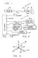
- Fig. 1 shows the advantageous apparatus for high speed payout of optical fiber 10 of the present invention in a deployed state.
- the apparatus 10 includes a pod 12 to which the optical fiber under test 14 is attached at one end.
- the other end of the optical fiber 14 is attached to a parachute assembly 16.
- the parachute assembly 16 includes a parachute 18 which is attached to a canister or tube 20.
- a pulley 22 is mounted on an end of the tube 20.
- the fiber 14 is wound about the pulley 22 and attached to a transmitter within the tube 20.
- the pod 12 is attached to an aircraft (not shown).
- the canister 20 with the parachute 18 is ejected from the end of the pod 12 when the aircraft is up to speed and altitude.
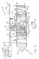
- Fig. 2 provides a sectional side view of the apparatus 10 of the present invention in an undeployed state.
- the pod 12 is simply a canister made of aluminum or other suitable material.
- the pod 12 is adapted to be carried on the exterior of an aircraft (not shown).
- the pod 12 has an aerodynamic nose cone 24 at one end.
- the pod 12 is open ended at the other end.
- the pod 12 has an exchangeable outer fairing 25.
- the fairing 25 is exchangeable to accommodate fiber optic canisters 32 within the pod 12 of various lengths.
- the fairing 25 has a lip 26 at the open end of the pod 12.
- the lip 26 has an annular smooth flaired teflon ring 27 within the periphery thereof.
- the teflon ring 27 is provided to minimize possible damage to the fiber 14 during payout caused by contact with the end of the fairing 25.
- a bulkhead 28 is provided within the pod 12 in a plane normal to the longitudinal axis thereof.
- a support rod 29 extends from the center of the bulkhead 28.
- Two instrumented mounting rings 30 and a fiber optic canister assembly 32 are mounted on the support rod 29.
- the mounting rings 30, together with the support rod, and the bulkhead, serve as a letoff stand.
- the letoff stand is instrumented to measure axial (pulling) and torsion (twisting) forces on the fiber optic canister 32.
- the torsion force is exerted on the fiber optic canister 32 and is a measure of the tension of the fiber 14.
- Flexures 34 are mounted on flexures within the mounting ring 30 to facilitate these measurements.
- the flexures 34 are thin bending members of metal or other suitable material.
- Load cells or strain gages 36 and 37 are mounted on the flexures 34 to measure the axial and torsion forces, respectively. Load cells are well known in the art and may currently be purchased from a company named
- the fiber optic canister 32 consists of a bobbin on which the optical fiber 14 is wound.
- the leader is a small section of Kevlar which provides a protective sheath for the fiber.
- the leader 38 is fabricated on the end of the fiber 14 and includes one or more steel wires for rigidity and/or a teflon tube through which the fiber 14 is passed.
- the turns of fiber 14 pass across a turns counter 40.
- the turns counter 40 includes a lamp 42 and an optical detector 44 (shown in phantom). The detector is mounted to receive optical energy reflected off the fiber 14 as the fiber 14 unwinds in a helical or corkscrew fashion during payout.
- Associated electronics (not shown) counts pulses output by the detector 44 to provide an indication of the amount and rate of fiber payout.
- the fiber 14 is wrapped around the pulley 22 in the XMTR tube 20.
- the pulley 22 is attached to tube 20 through a conventional load cell 48 which measures fiber tension at the transmitter.
- the pulley 22 is partially visible through the access door 46 of the pod 12.
- a battery with a plurality of cells 50 and a printed circuit board 52 are also included within the tube 20.
- the battery 50 is of conventional design and provides power for the transmitter and associated electronics 55 (not shown) on the circuit board 52.
- An end plate 54 serves as a bulk head for the tube 20.
- the pin 56 extends through the end plate 54 and is attached to a ring 59. The remaining end of the pin 56 is attached to a parachute 18.
- the ring 59 is part of a release mechanism 60.
- the release mechanism 60 provides for the retention of the tube 20 in the pod 12 until parachute deployment. As discussed more fully below, when the parachute 18 is deployed, the parachute 18 pulls on the pin 56 which, in turn, pulls, on the ring 59. The ring pulls a linkage 62 which retracts pins 64 from notches 65 in the pod 12 (Fig. 2) through guide blocks 66.
- the parachute 18 is also located within the tube 20.
- the parachute 18 is a small spring loaded chute such as a drogue chute.
- drogue chutes are small chutes that aid in the deployment in large chutes.
- the chute 18 is spring loaded to aid in deployment.
- the parachute 18 is retained within the tube 20 by a door 68.
- the door 68 is pivotally attached to the tube 20 at point A.
- the upper end of the door 68 is retained by a release mechanism 70.
- the release mechanism 70 may be a solenoid based release mechanism of conventional design.
- the release mechanism 70 is mounted on a mounting plate 72.
- the mounting plate 72 is adapted for ready attachment to a host aircraft (not shown).
- the plate 72 includes an extension 74 from which the pod 12 hangs.
- Wires 76 run from the load cells 36 on the flexure ring 30 to an optional receiver 78 and/or recorder 80 located in the host aircraft.
- a camera 82 may be mounted in the undercarriage of the aircraft to film the deployment of the parachute 18 and the payout of fiber 14.
- a brake mechanism 90 is included on the pod 12 to retain the fiber 14 within the bobbin 32 during aborted tests.
- the brake mechanism 90 includes a solenoid 92. When activated, the solenoid 90 moves a linkage 94 which disengages a catch 96. The catch 96 releases a foot or pin 100 to move in response to a spring 98. The pin 100 moves through a mounting ring 102 into contact with the fiber 14 pinning it to the bobbin 32.
- Fig. 4 provides a simple illustrative test circuit 81 for use in connection with the present invention.
- the circuit 81 is adapted to provide input to the recorder 80 from the load cells 36 and 37 directly and the load cell 50 via the transmitter 55 mounted in the parachute tube 20 and the receiver 78, the turns counter 40, a microphone 84, and a thermistor 86 mounted in the pod 12.
- the transmitter 55 and receiver 78 are of conventional design.
- the transmitter 55 provides a continuous wave signal which is modulated with a signal which represents the tension on the fiber 14 from the load cell 50.
- the apparatus 10 allows for the practice of the method of the invention which includes the steps of a) mounting a fiber 14 under test within a vehicle 12; b) attaching a parachute 18 to the fiber 14; c) moving the vehicle 12 in the test environment; and d) deploying the parachute 18 such that the drag caused by the parachute in the air or fluid moving about to the vehicle 12 is effective to pull the fiber 14 from the bobbin 32.
Abstract
Description
- The present invention relates to fiber optic communication systems. More specifically, the present invention relates to techniques for payout testing of optical fibers.
- While the present invention is described herein with reference to illustrative embodiments for particular applications, it should be understood that the invention is not limited thereto. Those having ordinary skill in the art and access to the teachings provided herein will recognize additional modifications, applications, and embodiments within the scope thereof and additional fields in which the present invention would be of significant utility.
- Fiber optic guidance using a high speed payout of optical fiber offers the potential for low cost, precision guidance for both air and surface launched vehicles. This emerging technology offers considerable promise in terms of guidance accuracy, security and flexibility. Although a significant technical base has been established for high speed payout of optical fiber, there remains a need in the art for further developments in this area.
- For example, the evaluation of the optical performance of the fiber during laboratory payout is very difficult. Significant modulation of the optical signal during payout has been experienced with virtually all of the currently known conventional laboratory techniques. As this modulation is not believed to be present during various actual flight test programs, this suggests that the laboratory payout techniques are not an accurate simulation of actual flight. Accordingly, alternative test procedures have been proposed and used to obtain certain critical engineering data regarding the optical performance of the fiber during payout. However, each of these tests has one or more significant shortcomings.
- For example, one test involves the use of the fiber in an actual airborne vehicle. While this test provides a accurate data on actual in flight performance, the use and recovery of the airborne vehicle is prohibitively expensive. The airborne vehicle is difficult, if not impossible to instrument, i.e., with cameras and the like. Further, in situations where the vehicle on which the fiber will be used is not available, i.e., where the actual vehicle is under development, the test may not be as representative as possible with other test programs.
- Thus, there is a need in the art for an inexpensive yet representative in-flight high speed optic fiber payout test apparatus and/or procedure.
- The need in the art is addressed by the method and apparatus for payout testing of an optical fiber of the present invention. The invention involves the attachment of a pod to a high speed aircraft with a parachute released during flight to initiate payout. The apparatus of the invention includes a bobbin mounted on a craft for retaining a coil of optical fiber and a parachute for using the air or fluid flow past the craft when the craft is in motion to pull the fiber from the coil. In a specific embodiment, the invention includes an electro-optical circuit for sending and receiving an optical signal along the fiber. Further, more specific, embodiments contemplate the use of load cells on the craft and parachute ends of the fiber to measure tension. This information is then transmitted to a receiver for analysis and/or storage. Other specific embodiments include a brake for inhibiting the payout of fiber during aborted test runs and a turns counter for providing a measure of the rate and amount of fiber payout.
-
- Fig. 1 shows the advantageous apparatus for high speed payout of optical fiber of the present invention in a deployed state.
- Fig. 2 provides a sectional side view of the apparatus of the present invention in an undeployed state.
- Fig. 3 is a rear view of the transmitter tube release mechanism utilized in the present invention.
- Fig. 4 provides a simple illustrative test circuit for use in connection with the present invention.
- Illustrative embodiments and exemplary applications will now be described with reference to the accompanying drawings to disclose the advantageous teachings of the present invention.
- Fig. 1 shows the advantageous apparatus for high speed payout of
optical fiber 10 of the present invention in a deployed state. Theapparatus 10 includes apod 12 to which the optical fiber undertest 14 is attached at one end. The other end of theoptical fiber 14 is attached to aparachute assembly 16. Theparachute assembly 16 includes aparachute 18 which is attached to a canister ortube 20. Apulley 22 is mounted on an end of thetube 20. As discussed more fully below, thefiber 14 is wound about thepulley 22 and attached to a transmitter within thetube 20. Thepod 12 is attached to an aircraft (not shown). Thecanister 20 with theparachute 18 is ejected from the end of thepod 12 when the aircraft is up to speed and altitude. - Fig. 2 provides a sectional side view of the
apparatus 10 of the present invention in an undeployed state. Thepod 12 is simply a canister made of aluminum or other suitable material. Thepod 12 is adapted to be carried on the exterior of an aircraft (not shown). Hence, thepod 12 has anaerodynamic nose cone 24 at one end. Thepod 12 is open ended at the other end. Thepod 12 has an exchangeableouter fairing 25. Thefairing 25 is exchangeable to accommodate fiberoptic canisters 32 within thepod 12 of various lengths. Thefairing 25 has alip 26 at the open end of thepod 12. Thelip 26 has an annular smoothflaired teflon ring 27 within the periphery thereof. Theteflon ring 27 is provided to minimize possible damage to thefiber 14 during payout caused by contact with the end of thefairing 25. - A
bulkhead 28 is provided within thepod 12 in a plane normal to the longitudinal axis thereof. Asupport rod 29 extends from the center of thebulkhead 28. Two instrumentedmounting rings 30 and a fiberoptic canister assembly 32 are mounted on thesupport rod 29. Themounting rings 30, together with the support rod, and the bulkhead, serve as a letoff stand. The letoff stand is instrumented to measure axial (pulling) and torsion (twisting) forces on the fiberoptic canister 32. The torsion force is exerted on the fiberoptic canister 32 and is a measure of the tension of thefiber 14.Flexures 34 are mounted on flexures within themounting ring 30 to facilitate these measurements. Theflexures 34 are thin bending members of metal or other suitable material. Load cells orstrain gages flexures 34 to measure the axial and torsion forces, respectively. Load cells are well known in the art and may currently be purchased from a company named Interface in Tempe, Arizona. - The fiber
optic canister 32 consists of a bobbin on which theoptical fiber 14 is wound. During payout, the fiber initially unwinds from the bobbin using aleader 38. The leader is a small section of Kevlar which provides a protective sheath for the fiber. Theleader 38 is fabricated on the end of thefiber 14 and includes one or more steel wires for rigidity and/or a teflon tube through which thefiber 14 is passed. During payout, the turns offiber 14 pass across aturns counter 40. The turns counter 40 includes alamp 42 and an optical detector 44 (shown in phantom). The detector is mounted to receive optical energy reflected off thefiber 14 as thefiber 14 unwinds in a helical or corkscrew fashion during payout. Associated electronics (not shown) counts pulses output by thedetector 44 to provide an indication of the amount and rate of fiber payout. - The
fiber 14 is wrapped around thepulley 22 in theXMTR tube 20. Thepulley 22 is attached totube 20 through aconventional load cell 48 which measures fiber tension at the transmitter. Thepulley 22 is partially visible through theaccess door 46 of thepod 12. A battery with a plurality ofcells 50 and a printed circuit board 52 (both shown in phantom) are also included within thetube 20. Thebattery 50 is of conventional design and provides power for the transmitter and associated electronics 55 (not shown) on thecircuit board 52. Anend plate 54 serves as a bulk head for thetube 20. Thepin 56 extends through theend plate 54 and is attached to aring 59. The remaining end of thepin 56 is attached to aparachute 18. Thering 59 is part of arelease mechanism 60. As shown in the rear view of Fig. 3, therelease mechanism 60 provides for the retention of thetube 20 in thepod 12 until parachute deployment. As discussed more fully below, when theparachute 18 is deployed, theparachute 18 pulls on thepin 56 which, in turn, pulls, on thering 59. The ring pulls alinkage 62 which retractspins 64 fromnotches 65 in the pod 12 (Fig. 2) through guide blocks 66. - As shown in Fig. 2, the
parachute 18 is also located within thetube 20. Theparachute 18 is a small spring loaded chute such as a drogue chute. As is known in the art, drogue chutes are small chutes that aid in the deployment in large chutes. Thechute 18 is spring loaded to aid in deployment. Theparachute 18 is retained within thetube 20 by adoor 68. Thedoor 68 is pivotally attached to thetube 20 at point A. The upper end of thedoor 68 is retained by arelease mechanism 70. Therelease mechanism 70 may be a solenoid based release mechanism of conventional design. Therelease mechanism 70 is mounted on a mountingplate 72. The mountingplate 72 is adapted for ready attachment to a host aircraft (not shown). Theplate 72 includes anextension 74 from which thepod 12 hangs. - Wires 76 run from the
load cells 36 on theflexure ring 30 to anoptional receiver 78 and/orrecorder 80 located in the host aircraft. Acamera 82 may be mounted in the undercarriage of the aircraft to film the deployment of theparachute 18 and the payout offiber 14. - As shown in Fig. 2, a
brake mechanism 90 is included on thepod 12 to retain thefiber 14 within thebobbin 32 during aborted tests. Thebrake mechanism 90 includes asolenoid 92. When activated, thesolenoid 90 moves alinkage 94 which disengages acatch 96. Thecatch 96 releases a foot or pin 100 to move in response to aspring 98. Thepin 100 moves through a mountingring 102 into contact with thefiber 14 pinning it to thebobbin 32. - Fig. 4 provides a simple
illustrative test circuit 81 for use in connection with the present invention. Thecircuit 81 is adapted to provide input to therecorder 80 from theload cells load cell 50 via thetransmitter 55 mounted in theparachute tube 20 and thereceiver 78, the turns counter 40, amicrophone 84, and athermistor 86 mounted in thepod 12. Thetransmitter 55 andreceiver 78 are of conventional design. In the preferred embodiment, thetransmitter 55 provides a continuous wave signal which is modulated with a signal which represents the tension on thefiber 14 from theload cell 50. - Thus, the
apparatus 10 allows for the practice of the method of the invention which includes the steps of a) mounting afiber 14 under test within avehicle 12; b) attaching aparachute 18 to thefiber 14; c) moving thevehicle 12 in the test environment; and d) deploying theparachute 18 such that the drag caused by the parachute in the air or fluid moving about to thevehicle 12 is effective to pull thefiber 14 from thebobbin 32. - Thus, the present invention has been described herein with reference to a particular embodiment for a particular application. Those having ordinary skill in the art and access to the present teachings will recognize additional modifications applications and embodiments within the scope thereof. For example, the invention is not limited to use with aircraft, the invention may be used with hydrodynamic vehicles without departing from the scope of the present invention.
- It is therefore intended by the appended claims to cover any and all such applications, modifications and embodiments within the scope of the present invention.
Claims (17)
bobbin means mounted on a craft for retaining a coil of said optical fiber and
parachute means for using the air or fluid flow past said craft when said craft is in motion to pull said fiber from said coil.
bobbin means mounted on a craft for retaining a coil of said optical fiber;
parachute means including a parachute attached to said fiber for using the air or fluid flow past said craft when said craft is in motion to pull said fiber from said coil;
first load cell means for measuring the tension in said fiber at said craft;
second load cell means for measuring the tension in said fiber at said parachute; and
electro-optical circuit means functionally connected to said first and second load cell means for sending and receiving an optical signal along said optical fiber representative of the tension in said fiber as measured by said first and second load cell means.
Applications Claiming Priority (2)
| Application Number | Priority Date | Filing Date | Title |
|---|---|---|---|
| US07/359,199 US4935620A (en) | 1989-05-31 | 1989-05-31 | Method and apparatus for flight payout testing of optical fibers |
| US359199 | 1989-05-31 |
Publications (3)
| Publication Number | Publication Date |
|---|---|
| EP0400832A2 true EP0400832A2 (en) | 1990-12-05 |
| EP0400832A3 EP0400832A3 (en) | 1992-07-01 |
| EP0400832B1 EP0400832B1 (en) | 1995-01-04 |
Family
ID=23412755
Family Applications (1)
| Application Number | Title | Priority Date | Filing Date |
|---|---|---|---|
| EP90305161A Expired - Lifetime EP0400832B1 (en) | 1989-05-31 | 1990-05-14 | Improved method and apparatus for flight payout testing of optical fibers |
Country Status (7)
| Country | Link |
|---|---|
| US (1) | US4935620A (en) |
| EP (1) | EP0400832B1 (en) |
| JP (1) | JP2545487B2 (en) |
| CA (1) | CA2015023C (en) |
| DE (1) | DE69015699T2 (en) |
| IL (1) | IL94095A0 (en) |
| NO (1) | NO902105L (en) |
Cited By (1)
| Publication number | Priority date | Publication date | Assignee | Title |
|---|---|---|---|---|
| CN109100216A (en) * | 2018-09-17 | 2018-12-28 | 江西洪都航空工业集团有限责任公司 | A kind of missile block hanging load tool structure |
Families Citing this family (8)
| Publication number | Priority date | Publication date | Assignee | Title |
|---|---|---|---|---|
| US5058969A (en) * | 1990-05-09 | 1991-10-22 | Hughes Aircraft Company | Optical fiber dispensing system |
| US5031982A (en) * | 1990-05-23 | 1991-07-16 | Hughes Aircraft Company | Flexible payout duct |
| US5186414A (en) * | 1992-04-20 | 1993-02-16 | The United States Of America As Represented By The Secretary Of The Navy | Hybrid data link |
| US5220632A (en) * | 1992-06-24 | 1993-06-15 | Hughes Aircraft Company | Preparation of an optical fiber canister |
| US5322997A (en) * | 1993-07-06 | 1994-06-21 | The United States Of America As Represented By The Secretary Of The Navy | Optic fiber payout test apparatus having a projectile track system with dual rails |
| US6510776B2 (en) * | 2001-05-11 | 2003-01-28 | The United States Of America As Represented By The Secretary Of The Navy | Immediate battle damage assessment of missile attack effectiveness |
| CN102879178B (en) * | 2012-09-10 | 2015-02-25 | 凯迈(洛阳)测控有限公司 | External hanging testing device |
| CN116776043B (en) * | 2023-08-17 | 2023-11-07 | 四川腾盾科技有限公司 | Method for predicting motion trail of parachute landing nacelle of large unmanned aerial vehicle |
Family Cites Families (5)
| Publication number | Priority date | Publication date | Assignee | Title |
|---|---|---|---|---|
| JPS4533540Y1 (en) * | 1967-07-08 | 1970-12-21 | ||
| JPS5683378A (en) * | 1979-12-10 | 1981-07-07 | Sanwa Denshi Kiki Kk | Parachute opening system for model plane |
| US4777660A (en) * | 1984-11-06 | 1988-10-11 | Optelecom Incorporated | Retroreflective optical communication system |
| JPH0693047B2 (en) * | 1987-07-29 | 1994-11-16 | 防衛庁技術研究本部長 | Optical fiber reel for high speed and high tilt angle feeding |
| US4853900A (en) * | 1987-10-19 | 1989-08-01 | The United States Of America As Represented By The Secretary Of The Navy | Stabilized suspension for immersible apparatus |
-
1989
- 1989-05-31 US US07/359,199 patent/US4935620A/en not_active Expired - Lifetime
-
1990
- 1990-04-17 IL IL94095A patent/IL94095A0/en unknown
- 1990-04-20 CA CA002015023A patent/CA2015023C/en not_active Expired - Fee Related
- 1990-05-11 NO NO90902105A patent/NO902105L/en unknown
- 1990-05-14 DE DE69015699T patent/DE69015699T2/en not_active Expired - Fee Related
- 1990-05-14 EP EP90305161A patent/EP0400832B1/en not_active Expired - Lifetime
- 1990-05-31 JP JP2140114A patent/JP2545487B2/en not_active Expired - Lifetime
Non-Patent Citations (1)
| Title |
|---|
| No relevant documents have been disclosed. * |
Cited By (2)
| Publication number | Priority date | Publication date | Assignee | Title |
|---|---|---|---|---|
| CN109100216A (en) * | 2018-09-17 | 2018-12-28 | 江西洪都航空工业集团有限责任公司 | A kind of missile block hanging load tool structure |
| CN109100216B (en) * | 2018-09-17 | 2021-05-18 | 江西洪都航空工业集团有限责任公司 | Guided missile slider hanging and loading tool structure |
Also Published As
| Publication number | Publication date |
|---|---|
| IL94095A0 (en) | 1991-01-31 |
| JP2545487B2 (en) | 1996-10-16 |
| US4935620A (en) | 1990-06-19 |
| NO902105D0 (en) | 1990-05-11 |
| EP0400832B1 (en) | 1995-01-04 |
| DE69015699T2 (en) | 1995-05-11 |
| CA2015023A1 (en) | 1990-11-30 |
| EP0400832A3 (en) | 1992-07-01 |
| JPH0323407A (en) | 1991-01-31 |
| CA2015023C (en) | 1994-08-02 |
| NO902105L (en) | 1990-12-03 |
| DE69015699D1 (en) | 1995-02-16 |
Similar Documents
| Publication | Publication Date | Title |
|---|---|---|
| US4935620A (en) | Method and apparatus for flight payout testing of optical fibers | |
| JP2567100B2 (en) | Compact acceleration measurement recorder | |
| WO2011134931A1 (en) | Apparatus and method for measuring an air pressure and system for detecting air data | |
| CN106124168B (en) | A kind of fiber stress strain testing method | |
| US5461926A (en) | Single-ended optical fiber strain sensor for measuring maximum strain | |
| Nikolayev et al. | Fiber optic sensors for parachute systems monitoring | |
| US5461927A (en) | Optical fiber strain sensor for measuring maximum strain | |
| Tanno et al. | Aerodynamic characteristics of a free-flight scramjet vehicle in shock tunnel | |
| US5103678A (en) | Fiber peel force measuring apparatus | |
| US3337004A (en) | Impact energy absorber | |
| CN113428381B (en) | Device and method for determining time period of catapult impact action of airplane suspension | |
| US3310978A (en) | Fiber optic vibration transducer and analyzer | |
| Stasicki et al. | Application of high-speed videography for in-flight deformation measurements of aircraft propellers | |
| Dayman Jr | Free-flight testing in high-speed wind tunnels | |
| Robinson | Dynamic response of a family of axisymmetric hammerhead models to unsteady aerodynamic loading | |
| RU2072538C1 (en) | Device for measuring vertical gradient of magnetic flux density of earth in stratosphere and vertical gradient increment | |
| US5322997A (en) | Optic fiber payout test apparatus having a projectile track system with dual rails | |
| JPS63163135A (en) | Wind tunnel test apparatus | |
| Benjamin et al. | Microshell®-tipped optical fibers as sensors of high-pressure pulses in adverse environments | |
| TYAGI et al. | Performance data acquisition from flexible aerodynamic decelerators | |
| US5456103A (en) | Measurement of fiber drift | |
| JP2765293B2 (en) | Aircraft dump test measurement system | |
| Hoffman et al. | Impact energy absorber Patent | |
| Anghileri et al. | Experimental and numerical activity on impacts on water surface | |
| CA1050301A (en) | Apparatus for measuring the proprieties of fluids |
Legal Events
| Date | Code | Title | Description |
|---|---|---|---|
| PUAI | Public reference made under article 153(3) epc to a published international application that has entered the european phase |
Free format text: ORIGINAL CODE: 0009012 |
|
| AK | Designated contracting states |
Kind code of ref document: A2 Designated state(s): CH DE FR GB IT LI NL SE |
|
| PUAL | Search report despatched |
Free format text: ORIGINAL CODE: 0009013 |
|
| AK | Designated contracting states |
Kind code of ref document: A3 Designated state(s): CH DE FR GB IT LI NL SE |
|
| 17P | Request for examination filed |
Effective date: 19921210 |
|
| 17Q | First examination report despatched |
Effective date: 19930701 |
|
| GRAA | (expected) grant |
Free format text: ORIGINAL CODE: 0009210 |
|
| AK | Designated contracting states |
Kind code of ref document: B1 Designated state(s): CH DE FR GB IT LI NL SE |
|
| REF | Corresponds to: |
Ref document number: 69015699 Country of ref document: DE Date of ref document: 19950216 |
|
| ET | Fr: translation filed | ||
| ITF | It: translation for a ep patent filed |
Owner name: SOCIETA' ITALIANA BREVETTI S.P.A. |
|
| PLBE | No opposition filed within time limit |
Free format text: ORIGINAL CODE: 0009261 |
|
| STAA | Information on the status of an ep patent application or granted ep patent |
Free format text: STATUS: NO OPPOSITION FILED WITHIN TIME LIMIT |
|
| 26N | No opposition filed | ||
| PGFP | Annual fee paid to national office [announced via postgrant information from national office to epo] |
Ref country code: FR Payment date: 19960411 Year of fee payment: 7 |
|
| PGFP | Annual fee paid to national office [announced via postgrant information from national office to epo] |
Ref country code: NL Payment date: 19960417 Year of fee payment: 7 |
|
| PGFP | Annual fee paid to national office [announced via postgrant information from national office to epo] |
Ref country code: SE Payment date: 19960418 Year of fee payment: 7 |
|
| PGFP | Annual fee paid to national office [announced via postgrant information from national office to epo] |
Ref country code: GB Payment date: 19960419 Year of fee payment: 7 |
|
| PGFP | Annual fee paid to national office [announced via postgrant information from national office to epo] |
Ref country code: DE Payment date: 19960424 Year of fee payment: 7 |
|
| PGFP | Annual fee paid to national office [announced via postgrant information from national office to epo] |
Ref country code: CH Payment date: 19960502 Year of fee payment: 7 |
|
| PG25 | Lapsed in a contracting state [announced via postgrant information from national office to epo] |
Ref country code: GB Effective date: 19970514 |
|
| PG25 | Lapsed in a contracting state [announced via postgrant information from national office to epo] |
Ref country code: SE Effective date: 19970515 |
|
| PG25 | Lapsed in a contracting state [announced via postgrant information from national office to epo] |
Ref country code: LI Free format text: LAPSE BECAUSE OF NON-PAYMENT OF DUE FEES Effective date: 19970531 Ref country code: CH Free format text: LAPSE BECAUSE OF NON-PAYMENT OF DUE FEES Effective date: 19970531 |
|
| PG25 | Lapsed in a contracting state [announced via postgrant information from national office to epo] |
Ref country code: NL Effective date: 19971201 |
|
| GBPC | Gb: european patent ceased through non-payment of renewal fee |
Effective date: 19970514 |
|
| REG | Reference to a national code |
Ref country code: CH Ref legal event code: PL |
|
| PG25 | Lapsed in a contracting state [announced via postgrant information from national office to epo] |
Ref country code: FR Free format text: LAPSE BECAUSE OF NON-PAYMENT OF DUE FEES Effective date: 19980130 |
|
| EUG | Se: european patent has lapsed |
Ref document number: 90305161.3 |
|
| NLV4 | Nl: lapsed or anulled due to non-payment of the annual fee |
Effective date: 19971201 |
|
| PG25 | Lapsed in a contracting state [announced via postgrant information from national office to epo] |
Ref country code: DE Free format text: LAPSE BECAUSE OF NON-PAYMENT OF DUE FEES Effective date: 19980203 |
|
| REG | Reference to a national code |
Ref country code: FR Ref legal event code: ST |
|
| PG25 | Lapsed in a contracting state [announced via postgrant information from national office to epo] |
Ref country code: IT Free format text: LAPSE BECAUSE OF NON-PAYMENT OF DUE FEES;WARNING: LAPSES OF ITALIAN PATENTS WITH EFFECTIVE DATE BEFORE 2007 MAY HAVE OCCURRED AT ANY TIME BEFORE 2007. THE CORRECT EFFECTIVE DATE MAY BE DIFFERENT FROM THE ONE RECORDED. Effective date: 20050514 |