EP0399622B1 - Ground working device - Google Patents
Ground working device Download PDFInfo
- Publication number
- EP0399622B1 EP0399622B1 EP90201331A EP90201331A EP0399622B1 EP 0399622 B1 EP0399622 B1 EP 0399622B1 EP 90201331 A EP90201331 A EP 90201331A EP 90201331 A EP90201331 A EP 90201331A EP 0399622 B1 EP0399622 B1 EP 0399622B1
- Authority
- EP
- European Patent Office
- Prior art keywords
- sections
- supporting arms
- working member
- ground working
- main supporting
- Prior art date
- Legal status (The legal status is an assumption and is not a legal conclusion. Google has not performed a legal analysis and makes no representation as to the accuracy of the status listed.)
- Expired - Lifetime
Links
Images


Classifications
-
- A—HUMAN NECESSITIES
- A01—AGRICULTURE; FORESTRY; ANIMAL HUSBANDRY; HUNTING; TRAPPING; FISHING
- A01B—SOIL WORKING IN AGRICULTURE OR FORESTRY; PARTS, DETAILS, OR ACCESSORIES OF AGRICULTURAL MACHINES OR IMPLEMENTS, IN GENERAL
- A01B29/00—Rollers
-
- Y—GENERAL TAGGING OF NEW TECHNOLOGICAL DEVELOPMENTS; GENERAL TAGGING OF CROSS-SECTIONAL TECHNOLOGIES SPANNING OVER SEVERAL SECTIONS OF THE IPC; TECHNICAL SUBJECTS COVERED BY FORMER USPC CROSS-REFERENCE ART COLLECTIONS [XRACs] AND DIGESTS
- Y10—TECHNICAL SUBJECTS COVERED BY FORMER USPC
- Y10S—TECHNICAL SUBJECTS COVERED BY FORMER USPC CROSS-REFERENCE ART COLLECTIONS [XRACs] AND DIGESTS
- Y10S56/00—Harvesters
- Y10S56/12—Brush
Definitions
- the invention relates to a ground working device, comprising a substantially cylindrical brush-like ground working member, which is mounted between two main supporting arms for rotation about a substantially horizontal axis and is axially composed of a number of sections which are mutually connected and connected with two shaft end sections journalled in said main supporting arms respectively through couplings of the universal type, the coupling between each two sections being supported by an auxiliary supporting arm which extends into the travelling direction and pivotally engages a connecting bar extending between said main supporting arms parallel to and in front of said ground working member.
- a ground working device is known from GB-A-116 429.
- a ground working member in the form of a rotary brush or sweeping roll composed of a number of universally pivotably connected sections such as in the well-known device has the advantage, that the ground working member can adapt itself to irregularities of the surface to be worked, which is to be seen as a condition for a uniform treatment.
- this aim is achieved in that the couplings between the sections are consituted by intermediary shaft sections, the ends of which are provided with thickenings, which have a non-circular cross-sectional shape and are axially slightly convex in shape, said thickenings engaging into correspondingly cross-sectionally shaped recesses in the opposing ends of adjacent sections, whereas both the axis of the ground working member and the connecting bar are located at substantially the same level, so that the auxiliary supporting arms are taking a substantially horizontal position and the rotational axis of the working member will be kept - as seen in the horizontal plane, substantially straight.
- the device shown in the drawing comprises a rotary brush or sweeping roll 1, which is rotatably suspended between two supporting arms 2, which may be mounted, e.g. in a rearwardly or forwardly extending fashion, on a machine or vehicle, such as a tractor.
- the brush 1 may be driven by means of a sprocket wheel 3, which is driven in turn, via a chain 4, by a sprocket wheel 5 which is coupled with a drive shaft 6, e.g. the stub axle of a tractor.
- the rotary brush or sweeping roll 1 is composed of a number (five in the example shown) of sections 7. These sections each comprise a substantially cylindrical body 8, carrying the active elements, viz. the bristles 9.
- the brush shaft consists of two shaft end portions 10 which are each journalled in the free end of a supporting arm 2, and a plurality (four in the example shown) intermediary shaft sections 11, the latter forming in fact coupling members between the adjacent brush sections.
- the sprocket wheel 3 is fastened on one of the shaft end portions 10.
- the intermediary shaft sections 11 have, at each end, a thickening 12 of a non-circular, e.g. hexagonal cross-sectional shape. These thickenings engage into correspondingly shaped, e.g. hexagonally formed recesses 13 in the opposite ends of two adjacent brush sections 7 (vide in particular fig. 5).
- the (hexagonally-shaped) thickenings 12 are axially slightly convax in shape, due to which the brush sections 7 may pivot through a certain angle in universal directions relative to the respective thickenings 12.
- the thickenings 12 may slide through a slight distance axially within the respective recesses 13.
- a rotary brush 1 constructed in this way may adapt itself to unevennesses of the ground surface to be worked.
- the brush sections are deviated upwardly to adapt to rises in the ground, whereas the downwardly pointing arrows indicate an adaptation of the brush sections to a lowering in the ground.
- auxiliary arms 14 are each constituted by an upstanding plate member 16, provided with a bearing 17 for the cylindrical central portion 18 of the respective shaft end portion 10 or the respective intermediate shaft section 11.
- the plate members 16 are each connected to the bar 15 by means of a lever 20 to which it is pivotally connected at 19. (Vide in particular fig. 7).
- the plate members 16 also serve as supports for two series of rollers 21 and 22 of smaller diameter which are positioned in front of and behind the brush shaft respectively.
- the rollers 21 and 22 have a length corresponding to that of the brush sections 7.
- the forward rollers 21 as well as the rearward rollers 22 are mounted for mutual displacement such that they are allowed to follow the unevennesses in the ground to be worked.
- the rearward rollers 22 are vertically adjustably mounted relative to the plate menbers 16 (vide fig. 3, 4 and 7).
- the opposing shaft ends 23 of each pair of adjacent rollers 22 are connected - by means of a rather flexible pin-slot connecting means 24 - to the lower end 25 of a vertical threaded rod 26, which is accommodated in the bushing-shaped terminal edge 27 of the respective plate member 16.
- the position of the nuts 28 along the threaded rod 26 determines the height of the brush shaft 18 at the respective plate member 16.
- the device according to the present invention is particularly suitable for use on golf courses and more particularly for filling up the vertical drainage holes made therein, by sand which has been previously spread as a layer onto the golf course.
- the bristles located adjacent the ends of the bodies 8 are implanted to extend slightly obliquely outwardly, so that the bristles at the opposing ends of adjacent brush sections will slightly overlap each other.
- these bristles will smoothly flex back each time they pass at those locations in front of and behind the brush, where the plate members 16 are projecting.
- the upper and lower edges of the plate members 16 are bevelled or rounded off (vide fig. 6).
- a bridge member 30 is extending also between the two supporting arms 2, the horizontal, rod-shaped portion 31 of which is located vertically above the brush shaft.
- the plate members 16 are each connected with said rod 31 by means of flexible cords 32 so as to limit the deviation of the brush sections in the downward direction e.g. when elevating the entire device by means of the supporting arms 2 from its operative position.
- the supporting arms 2 may, at their ends (not shown) turned away from the brush, be pivotally connected, about a horizontal transverse axis, to the carrying vehicle or machine.
- the supporting arms may pivot independently of each other, so that the brush may adapt itself to variations of the transverse sloping of the ground to be worked, occuring in the travelling direction.
- the bridge member 30 will have to be flexibly connected so as to allow mutual pivotal movements of the two supporting arms 2.
Landscapes
- Life Sciences & Earth Sciences (AREA)
- Engineering & Computer Science (AREA)
- Mechanical Engineering (AREA)
- Soil Sciences (AREA)
- Environmental Sciences (AREA)
- Soil Working Implements (AREA)
- Agricultural Machines (AREA)
Abstract
Description
- The invention relates to a ground working device, comprising a substantially cylindrical brush-like ground working member, which is mounted between two main supporting arms for rotation about a substantially horizontal axis and is axially composed of a number of sections which are mutually connected and connected with two shaft end sections journalled in said main supporting arms respectively through couplings of the universal type, the coupling between each two sections being supported by an auxiliary supporting arm which extends into the travelling direction and pivotally engages a connecting bar extending between said main supporting arms parallel to and in front of said ground working member. Such a ground working device is known from GB-A-116 429.
- A ground working member in the form of a rotary brush or sweeping roll composed of a number of universally pivotably connected sections such as in the well-known device, has the advantage, that the ground working member can adapt itself to irregularities of the surface to be worked, which is to be seen as a condition for a uniform treatment.
- There is no disclosure in GB-A-116 469 with respect to the construction of the universal couplings both with respect to the mutual angling movability and the mutual axial movability of adjacent sections of the ground working member.
- A disadvantage of the well-known device is to be seen in that the suspension (through the auxiliary supporting arms) of the couplings between the sections is such, that these sections - while following the unevenesses of the ground to be worked - will also mutually pivot in the horizontal plane. As a result of this at least some of the sections of the ground working member will not properly track in the travelling direction of the device.
- It is therefore an object of the present invention to provide practically constructed universal couplings and to provide for a proper tracking of the various sections of the ground working member in the travelling direction of the machine.
- In accordance with the present invention this aim is achieved in that the couplings between the sections are consituted by intermediary shaft sections, the ends of which are provided with thickenings, which have a non-circular cross-sectional shape and are axially slightly convex in shape, said thickenings engaging into correspondingly cross-sectionally shaped recesses in the opposing ends of adjacent sections, whereas both the axis of the ground working member and the connecting bar are located at substantially the same level, so that the auxiliary supporting arms are taking a substantially horizontal position and the rotational axis of the working member will be kept - as seen in the horizontal plane, substantially straight.
- The invention will be hereinafter further explained with reference to the drawing, in which by way of example a sweeping device, provided with a flexible rotary brush according to the invention, has been shown.
- Fig. 1 is a perspective view of the device having a flexible rotary brush according to the invention;
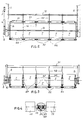
- fig. 2 is a plan view of the device of fig. 1;
- fig. 3 is a rear view of the device of fig. 1;
- fig. 4 shows a detail relating to the coupling between two supporting rollers;
- fig. 5 is a detailed longitudinal section of a coupling between two rotary brush sections;
- fig. 6 shows an axial section through a part of the rolling brush, showing in particular how the bristles are implanted and
- fig. 7 is a cross-sectional view along the line VII-VII in fig. 1.
- The device shown in the drawing comprises a rotary brush or sweeping roll 1, which is rotatably suspended between two supporting
arms 2, which may be mounted, e.g. in a rearwardly or forwardly extending fashion, on a machine or vehicle, such as a tractor. - The brush 1 may be driven by means of a
sprocket wheel 3, which is driven in turn, via achain 4, by asprocket wheel 5 which is coupled with adrive shaft 6, e.g. the stub axle of a tractor. - The rotary brush or sweeping roll 1 is composed of a number (five in the example shown) of
sections 7. These sections each comprise a substantiallycylindrical body 8, carrying the active elements, viz. thebristles 9. - The brush shaft consists of two
shaft end portions 10 which are each journalled in the free end of a supportingarm 2, and a plurality (four in the example shown)intermediary shaft sections 11, the latter forming in fact coupling members between the adjacent brush sections. Thesprocket wheel 3 is fastened on one of theshaft end portions 10. - The
intermediary shaft sections 11 have, at each end, athickening 12 of a non-circular, e.g. hexagonal cross-sectional shape. These thickenings engage into correspondingly shaped, e.g. hexagonally formedrecesses 13 in the opposite ends of two adjacent brush sections 7 (vide in particular fig. 5). The (hexagonally-shaped)thickenings 12 are axially slightly convax in shape, due to which thebrush sections 7 may pivot through a certain angle in universal directions relative to therespective thickenings 12. In addition thethickenings 12 may slide through a slight distance axially within therespective recesses 13. - In a similar manner the inwardly projecting ends of the
shaft end portions 10 are provided withthickenings 12, which engage into correspondingly shaped recesses of the outer brush sections 7 (which are disposed immediately adjacent the supporting arms 2). - In fig. 1 it is illustrated how a rotary brush 1 constructed in this way may adapt itself to unevennesses of the ground surface to be worked. At the upwardly directing arrows the brush sections are deviated upwardly to adapt to rises in the ground, whereas the downwardly pointing arrows indicate an adaptation of the brush sections to a lowering in the ground.
- In the horizontal plane mutual pivotal displacements of the brush sections are in fact undesired. For this reason the rotary brush is supported in the horizontal direction at each
intermediary shaft section 11 by means of aauxiliary arm 14 that extends into the travelling direction of the sweeping device and is pivotally connected to abar 15 extending between the supportingarms 2 parallel to theshaft end portions 10. - Due to the
auxiliary arms 14 the brush will, as seen from above, be kept substantially straight. - In the embodiment shown in the drawing the
auxiliary arms 14 are each constituted by anupstanding plate member 16, provided with abearing 17 for the cylindricalcentral portion 18 of the respectiveshaft end portion 10 or the respectiveintermediate shaft section 11. Theplate members 16 are each connected to thebar 15 by means of alever 20 to which it is pivotally connected at 19. (Vide in particular fig. 7). Theplate members 16 also serve as supports for two series ofrollers rollers brush sections 7. Theforward rollers 21 as well as therearward rollers 22 are mounted for mutual displacement such that they are allowed to follow the unevennesses in the ground to be worked. - Furthermore the
rearward rollers 22 are vertically adjustably mounted relative to the plate menbers 16 (vide fig. 3, 4 and 7). For this purpose the opposing shaft ends 23 of each pair ofadjacent rollers 22 are connected - by means of a rather flexible pin-slot connecting means 24 - to thelower end 25 of a vertical threadedrod 26, which is accommodated in the bushing-shaped terminal edge 27 of therespective plate member 16. The position of thenuts 28 along the threadedrod 26 determines the height of thebrush shaft 18 at therespective plate member 16. - The use of the series of
rollers - In this embodiment the device according to the present invention is particularly suitable for use on golf courses and more particularly for filling up the vertical drainage holes made therein, by sand which has been previously spread as a layer onto the golf course.
- When used in this way it is also important that there will be no forming of ridges of sand at the transitions between the brush sections. For this reason the bristles located adjacent the ends of the bodies 8 (vide in particular fig. 6) are implanted to extend slightly obliquely outwardly, so that the bristles at the opposing ends of adjacent brush sections will slightly overlap each other. When the brush is rotating, these bristles will smoothly flex back each time they pass at those locations in front of and behind the brush, where the
plate members 16 are projecting. For this purpose the upper and lower edges of theplate members 16 are bevelled or rounded off (vide fig. 6). - A
bridge member 30 is extending also between the two supportingarms 2, the horizontal, rod-shaped portion 31 of which is located vertically above the brush shaft. Theplate members 16 are each connected with saidrod 31 by means offlexible cords 32 so as to limit the deviation of the brush sections in the downward direction e.g. when elevating the entire device by means of the supportingarms 2 from its operative position. - The supporting
arms 2 may, at their ends (not shown) turned away from the brush, be pivotally connected, about a horizontal transverse axis, to the carrying vehicle or machine. Preferably the supporting arms may pivot independently of each other, so that the brush may adapt itself to variations of the transverse sloping of the ground to be worked, occuring in the travelling direction. For this purpose thebridge member 30 will have to be flexibly connected so as to allow mutual pivotal movements of the two supportingarms 2.
Claims (3)
- A ground working device, comprising a substantially cylindrical brush-like ground working member (1), which is mounted between two main supporting arms (2) for rotation about a substantially horizontal axis and is axially composed of a number of sections (7) which are mutually connected and connected with two shaft end sections (10) journalled in said main supporting arms (2) respectively through couplings (11-13) of the universal type, the coupling between each two sections (7) being supported by an auxiliary supporting arm (14) which extends into the travelling direction and pivotally engages a connecting bar (15) extending between said main supporting arms (2) parallel to and in front of said ground working member (1), characterized in that the couplings (11-13) between the sections (7) are consituted by intermediary shaft sections (11), the ends of which are provided with thickenings (12), which have a non-circular cross-sectional shape and are axially slightly convex in shape, said thickenings engaging into correspondingly cross-sectionally shaped recesses (13) in the opposing ends of adjacent sections (7), whereas both the axis of the ground working member (1) and the connecting bar (15) are located at substantially the same level, so that the auxiliary supporting arms (14) are taking a substantially horizontal position and the rotational axis of the working member (1) will be kept - as seen in the horizontal plane, substantially straight.
- A device according to claim 1, characterized in that each shaft end portion (10) is, at its inwardly directed end, also provided with a thickening (12) which engages into a recess (13) in the adjacent end face of the respective outer section (7).
- A device according to claims 1-2, characterized in that the thickenings (12) are slidable within said recesses (13).
Priority Applications (1)
| Application Number | Priority Date | Filing Date | Title |
|---|---|---|---|
| AT90201331T ATE84394T1 (en) | 1989-05-26 | 1990-05-23 | SOIL CULTIVATION DEVICE. |
Applications Claiming Priority (2)
| Application Number | Priority Date | Filing Date | Title |
|---|---|---|---|
| NL8901333A NL8901333A (en) | 1989-05-26 | 1989-05-26 | CYLINDRICAL SOIL TILLER. |
| NL8901333 | 1989-05-26 |
Publications (2)
| Publication Number | Publication Date |
|---|---|
| EP0399622A1 EP0399622A1 (en) | 1990-11-28 |
| EP0399622B1 true EP0399622B1 (en) | 1993-01-13 |
Family
ID=19854721
Family Applications (1)
| Application Number | Title | Priority Date | Filing Date |
|---|---|---|---|
| EP90201331A Expired - Lifetime EP0399622B1 (en) | 1989-05-26 | 1990-05-23 | Ground working device |
Country Status (6)
| Country | Link |
|---|---|
| US (1) | US5076367A (en) |
| EP (1) | EP0399622B1 (en) |
| AT (1) | ATE84394T1 (en) |
| CA (1) | CA2017546A1 (en) |
| DE (1) | DE69000755D1 (en) |
| NL (1) | NL8901333A (en) |
Families Citing this family (9)
| Publication number | Priority date | Publication date | Assignee | Title |
|---|---|---|---|---|
| US4926517A (en) | 1989-02-24 | 1990-05-22 | Smith Keith E | Sweeper |
| FR2688377B1 (en) * | 1992-03-11 | 1994-06-17 | Doucet Freres | PROCESS AND MACHINE FOR THE MAINTENANCE OF A PLANT GROUND OF GRASS, FOR EXAMPLE A TRACK OF RACING OR HIPPIC TRAINING ENGAZONNEE. |
| DE69410709T2 (en) * | 1993-07-28 | 1999-05-20 | Athar Int Serv Sa | Method and devices for marking lawns |
| US5477927A (en) * | 1994-01-26 | 1995-12-26 | Applied Design Technology, Ltd. | Turf maintenance and brushing machine |
| AU726437B2 (en) * | 1997-01-30 | 2000-11-09 | Peter Harry Whitton | Turf renovation sweeper and grader |
| US5924495A (en) * | 1997-03-21 | 1999-07-20 | Gravois; Dean A. | Apparatus and method for removal of surface debris from crop rows |
| DE102007027422A1 (en) | 2007-06-14 | 2008-12-18 | Wiedenmann Gmbh | Soil cultivation device with pretensioned roller or roller element |
| CN105191523A (en) * | 2015-09-10 | 2015-12-30 | 蚌埠市裔湾生态蔬菜农民专业合作社 | Land ploughing device |
| FR3110333B1 (en) * | 2020-05-19 | 2022-04-22 | Terrateck | Weeding roller for row of planting covered with a strip of plastic film |
Family Cites Families (12)
| Publication number | Priority date | Publication date | Assignee | Title |
|---|---|---|---|---|
| US599937A (en) * | 1898-03-01 | Ander gillies | ||
| GB116429A (en) * | 1917-09-25 | 1918-06-13 | Walter Barnett | Improvements in or relating to Road Sweeping Machines. |
| US1628874A (en) * | 1926-05-28 | 1927-05-17 | James A Eastes | Farm pulverizer |
| US2587463A (en) * | 1946-06-22 | 1952-02-26 | Wm Bros Boiler & Mfg Co | Tamping roller frame |
| US2644386A (en) * | 1947-10-09 | 1953-07-07 | John H Sutton | Rotary soil tiller |
| US2701889A (en) * | 1950-02-18 | 1955-02-15 | Leonard H Riddell | Brush support for mechanical road sweepers |
| US3650331A (en) * | 1970-03-23 | 1972-03-21 | Arnold A Dedoes | Tractor having hitch assembly for mounting a plurality of implements |
| DE2913815A1 (en) * | 1978-04-12 | 1979-10-18 | Patent Concern Nv | TILLAGE MACHINE |
| US4373590A (en) * | 1980-04-25 | 1983-02-15 | The Eversman Mfg. Company | Tilling apparatus |
| US4520873A (en) * | 1983-06-10 | 1985-06-04 | Eshet Eilon | Tractor-driven agricultural apparatus including a plurality of rotary-driven agricultural units |
| US4586444A (en) * | 1984-05-07 | 1986-05-06 | Cornelius Thiessen | Liquid chemical incorporator assembly |
| GB2198321B (en) * | 1986-10-23 | 1990-09-12 | Shotbolt Engineering Limited | Assembly of ground or plant treatment members |
-
1989
- 1989-05-26 NL NL8901333A patent/NL8901333A/en not_active Application Discontinuation
-
1990
- 1990-05-23 EP EP90201331A patent/EP0399622B1/en not_active Expired - Lifetime
- 1990-05-23 AT AT90201331T patent/ATE84394T1/en not_active IP Right Cessation
- 1990-05-23 DE DE9090201331T patent/DE69000755D1/en not_active Expired - Lifetime
- 1990-05-25 CA CA002017546A patent/CA2017546A1/en not_active Abandoned
- 1990-05-25 US US07/528,853 patent/US5076367A/en not_active Expired - Fee Related
Also Published As
| Publication number | Publication date |
|---|---|
| NL8901333A (en) | 1990-12-17 |
| ATE84394T1 (en) | 1993-01-15 |
| DE69000755D1 (en) | 1993-02-25 |
| EP0399622A1 (en) | 1990-11-28 |
| US5076367A (en) | 1991-12-31 |
| CA2017546A1 (en) | 1990-11-26 |
Similar Documents
| Publication | Publication Date | Title |
|---|---|---|
| EP0191523B1 (en) | An apparatus for soil working | |
| US5018587A (en) | Brush attachment | |
| EP0399622B1 (en) | Ground working device | |
| EP0021784B1 (en) | Rotary brush mounting | |
| EP0339231A3 (en) | Agricultural mowing and hay-making machine | |
| GB1587747A (en) | Soil cultivating implements | |
| CA1305628C (en) | Tool | |
| AU2009284693B2 (en) | Material handling | |
| US3930277A (en) | Mobile floor sweeper | |
| US6016584A (en) | Lateral sweeping apparatus | |
| GB1566605A (en) | Soil cultivating implements | |
| US5261218A (en) | Powered rake having debris windrowing mechanism | |
| US4706395A (en) | Ballast dressing unit on machines which dress and re-distribute railway road bed ballast | |
| US4280565A (en) | Soil working machine | |
| DE4319729A1 (en) | Self-propelled sweeper mechanism - has multi-sectional articulated arm, with additional horizontal pivot axis for third brush | |
| EP0189235B1 (en) | Soil cultivating implement | |
| EP0150080B1 (en) | Soil cultivating implements | |
| US3047969A (en) | Land leveler | |
| US4907652A (en) | Packer harrow implement | |
| GB1595126A (en) | Soil cultivating implements | |
| US4129978A (en) | Harvester swath pickup | |
| GB2128461A (en) | Soil cultivating implements | |
| EP1080621A1 (en) | Universal tool carrier | |
| GB2248757A (en) | A ground surface treating system | |
| DE4103537A1 (en) | Implement for soil cultivation - has compensating device for optimum positioning |
Legal Events
| Date | Code | Title | Description |
|---|---|---|---|
| PUAI | Public reference made under article 153(3) epc to a published international application that has entered the european phase |
Free format text: ORIGINAL CODE: 0009012 |
|
| AK | Designated contracting states |
Kind code of ref document: A1 Designated state(s): AT BE CH DE DK ES FR GB GR IT LI LU NL SE |
|
| 17P | Request for examination filed |
Effective date: 19901016 |
|
| 17Q | First examination report despatched |
Effective date: 19910612 |
|
| GRAA | (expected) grant |
Free format text: ORIGINAL CODE: 0009210 |
|
| AK | Designated contracting states |
Kind code of ref document: B1 Designated state(s): AT BE CH DE DK ES FR GB GR IT LI LU NL SE |
|
| PG25 | Lapsed in a contracting state [announced via postgrant information from national office to epo] |
Ref country code: IT Free format text: LAPSE BECAUSE OF FAILURE TO SUBMIT A TRANSLATION OF THE DESCRIPTION OR TO PAY THE FEE WITHIN THE PRE;WARNING: LAPSES OF ITALIAN PATENTS WITH EFFECTIVE DATE BEFORE 2007 MAY HAVE OCCURRED AT ANY TIME BEFORE 2007. THE CORRECT EFFECTIVE DATE MAY BE DIFFERENT FROM THE ONE RECORDED.SCRIBED TIME-LIMIT Effective date: 19930113 Ref country code: FR Effective date: 19930113 Ref country code: CH Effective date: 19930113 Ref country code: NL Effective date: 19930113 Ref country code: LI Effective date: 19930113 Ref country code: DE Effective date: 19930113 Ref country code: ES Free format text: THE PATENT HAS BEEN ANNULLED BY A DECISION OF A NATIONAL AUTHORITY Effective date: 19930113 Ref country code: BE Effective date: 19930113 Ref country code: DK Effective date: 19930113 Ref country code: GR Free format text: LAPSE BECAUSE OF FAILURE TO SUBMIT A TRANSLATION OF THE DESCRIPTION OR TO PAY THE FEE WITHIN THE PRESCRIBED TIME-LIMIT Effective date: 19930113 Ref country code: AT Effective date: 19930113 Ref country code: SE Effective date: 19930113 |
|
| REF | Corresponds to: |
Ref document number: 84394 Country of ref document: AT Date of ref document: 19930115 Kind code of ref document: T |
|
| REF | Corresponds to: |
Ref document number: 69000755 Country of ref document: DE Date of ref document: 19930225 |
|
| REG | Reference to a national code |
Ref country code: CH Ref legal event code: PL |
|
| PG25 | Lapsed in a contracting state [announced via postgrant information from national office to epo] |
Ref country code: LU Free format text: LAPSE BECAUSE OF NON-PAYMENT OF DUE FEES Effective date: 19930531 |
|
| EN | Fr: translation not filed | ||
| NLV1 | Nl: lapsed or annulled due to failure to fulfill the requirements of art. 29p and 29m of the patents act | ||
| PLBE | No opposition filed within time limit |
Free format text: ORIGINAL CODE: 0009261 |
|
| STAA | Information on the status of an ep patent application or granted ep patent |
Free format text: STATUS: NO OPPOSITION FILED WITHIN TIME LIMIT |
|
| 26N | No opposition filed | ||
| PG25 | Lapsed in a contracting state [announced via postgrant information from national office to epo] |
Ref country code: GB Effective date: 19940523 |
|
| GBPC | Gb: european patent ceased through non-payment of renewal fee |
Effective date: 19940523 |